A WiFi-enabled temperature sensor that uploads data online and texts when the temp is out of range. Also, an excessively documented guide to getting started with a simple internet-enabled project.
CONTENTS
- Background
- The Problem to Solve
- The Solution
- Why Read This
- Equipment:
- Time to Build
- Connect to the Internet
- Putting It All Together
- Conclusion
- But Wait, There's More
- What's Next
In my quest for knowledge I slightly turned my focus from doing programmy things to doing programmy things with microcontrollers. There's something so cool about seeing your program running around in the wild, outside of the confines of a laptop. After getting the basics down with an Arduino Uno (well, SparkFun's version of it) I decided to push myself a little bit with an Internet of Things project. The first project I could think of was connecting our downstairs closet to the internet...
When Kevin brews he needs to keep a close eye on the temperature of the beer for the first several days. This often means texts from him while he's at work checking on the temp and asking me to throw an ice pack into the water bath if necessary. Sometimes it gets hot in a hurry in the closet the beer is in or things cool down too much and don't ferment right. And sometimes I forget to check or I'm not home to tell him the temp. I hate ruining his beer. Also, I wanted a simple project that reads data from a sensor and sends that data to the internet, perhaps acting on it as well, like sending a text. This was the perfect opportunity for such a project.
A WiFi-enabled microcontroller (ESP8266 Thing Dev Board) with a waterproof temperature sensor (DS18B20) that transmits temperature data to ThingSpeak.com which in turn triggers IFTTT to send a text when the temp gets too high or low. Ta da! Kevin gets to keep an eye on his beer while at work and will get notified if things get too hot or cold. I also put an RGB LED on it that flashes red if it's too hot, blue if it's too cold and green if it's in the proper temp range, so you can see at a glance if the temp is good without going online.
I'm a beginner with microcontrollers. A real beginner. I had about 5,000 WTF moments while building this thing. I had no idea what I was doing when I started or what equipment I even needed. But I figured it all out and decided to excessively document the hell out of it for any other beginners out there trying to do the same kind of thing - and so I wouldn't have to reinvent the wheel if I forgot things and wanted to build another project.
ESP8266 Thing Dev Board ($16.50)
I spent two days researching what I needed to hook up to the internet and decided I needed some version of an ESP8266. A basic ESP8266 is a cheap little WiFi microcontroller that allows other microcontrollers to connect to a WiFi network. I think you can even operate it on its own without another microcontroller, but it only has a few pins and it seemed awfully complex to figure out all the fussy details. The pins don't fit into a breadboard, it only operates at 3.3 volts so you'd need something to regulate the voltage to it and you'd need some way to get the programs onto it. So I kept looking and found that SparkFun (as well as plenty of others like Adafruit) make breakout boards for the ESP8266 which make working with it easier. The one I settled on was the ESP8266 Thing Dev Board. Here are a few reasons why:
- Integrated FTDI USB-to-Serial chip: Without this you'd need a special cord or an FTDI breakout board to get your programs onto it. With the ESP8266 Thing Dev Board you can upload programs with a regular USB to micro-B cable. This seemed much easier (and cheaper) and less likely for me to have problems.
- Onboard 3.3V regulator: Plug it into a 5V wall charger or your computer and the Thing will regulate the power itself. No need for a logic level converter that I don't know how to use anyway. Less chance to blow things up.
- Cost: While the basic ESP8266 is only 5 or so dollars, I'd still have to hook it up to another Arduino and would still need to buy the power thingy and the FTDI thingy, so at $16.50 I'd actually be saving money.
- A few extra perks: Like onboard LED's, the ability to program it with the Arduino IDE that I was already familiar with, a power switch and the pins already soldered on.
Waterproof DS18B20 ($9.95)
Cheap enough, long 6' cord, seemed like a good basic choice.
LED - RGB Clear Common Cathode ($1.95)
I'm sure there are much cheaper ways to get these but I was already getting everything else through SparkFun so added this along with it. I wanted an RGB LED so I could have three colors (blue for cold, red for hot and green for good) coming from one spot, instead of wrestling with three separate LEDs.
5V/1A USB Wall Charger ($3.95)
USB to Micro-B Cable ($3.95)
Like I stated above, the ESP8266 Thing Dev Board has it's own power regulator so you can use a regular wall charger with it without blowing things up. You can also use the USB cord to program it.
If you're playing along at home you'll also need some jumper wires and three 330 ohm resisters, one 4.7K ohm resistor, and a mini breadboard.
Easier said than done. I followed the beginning of this tutorial from SparkFun to get things up and running. I was used to working with the Arduino IDE so I decided to stick with that. Most notably you'll need to add a board manager for the ESP8266, install the proper board manager and then choose the proper board from the dropdown menu. All details on this page. Then test it out with the sample code on the same page.
This didn't work for me. I kept getting espcomm errors everywhere. I tried what they recommended (selecting a generic board) but that didn't work either. (I have the "SparkFun ESP8266 Thing" selected) I tried a different USB cable and that didn't work. I nearly pulled my hair out trying to figure this out. Here's what DID work: Ground pin 0. First make sure the board is switched on so the power light is glowing. Then attach the board to a breadboard and connect the pin 0 to ground with a jumper wire. So, connect the first pin on the right to the 4th pin down on the right. Oddly, if I power down my device and then power it back up and pin 0 is still grounded my program won't run. I have to disconnect pin 0 from ground after powering up. I dunno. Also, later on once other pins were attached I didn't need to do this anymore. Someone more experienced than I am will have to explain it.
Also, I changed a file deep in an Arduino folder and I don't know if it would have worked without this change. But it didn't hurt. I changed boards.txt file so the line thing.upload.resetmethod=ck was now thing.upload.resetmethod=nodemcu. Path to file on Mac: /Users/{UserName}/Library/Arduino15/packages/esp8266/hardware/esp8266/2.4.1/boards.txt Possible path on Windows: \\Users\{UserName}\AppData\Local\Arduino15\packages\esp8266\hardware\esp8266\2.0.0\boards.txt.
Suddenly it worked! The little onboard LED was blinking away.
Again, EASIER SAID THAN DONE. The temp sensor is straightforward, only has has three wires. Connect the black one to ground, the red one to power (I connected it to the 5V pin on the left but the 3V3 pin probably works just as well), and the white one to a pin on your board. I hooked mine up to GPIO4. Didn't work. Turns out I needed two things: the 1-wire library and a resistor.
Connect a 4.7K resister between signal and power

I colored the legs of the resistor so you can see better how it goes. See how one leg is on the same row as the white wire and the other leg is on the same row as the red wire? That's where it goes. Now you don't have to tear your hair out, too.
Include the proper libraries
Go to Sketch > Include Libraries > Manage Libraries and download the OneWire library and the DallasTemperature library. I played around with it to make sure I could get it working right before moving on. I wrote a small program that takes the temp and spits it out to the serial monitor.
Test it with some code
Here's my sensor set up in the Arduino IDE before the setup function. Note that the white wire of my sensor is plugged into pin 4. Change that for your setup:
// INCLUDE LIBRARIES
#include <OneWire.h>
#include <DallasTemperature.h>

// TEMP SENSOR SET UP
// Data wire is plugged into port 4 on the Arduino
#define ONE_WIRE_BUS 4
// Setup a oneWire instance to communicate with any OneWire devices (not just Maxim/Dallas temperature ICs)
OneWire oneWire(ONE_WIRE_BUS);
// Pass oneWire reference to Dallas Temperature.
DallasTemperature sensors(&oneWire);
// Variable to store temp
float temp;
The setup function starts the temp library and begins the Serial monitor convo:
void setup() {
  // Start up the temperature library
  sensors.begin();

  // Start serial port
  Serial.begin(9600);
}
The loop gets the temp and prints it to serial every 1 second:
void loop() {

  // GET TEMP
  // call sensors.requestTemperatures() to issue a global temperature request to all devices on the bus
  Serial.print("Requesting temperatures...");
  // Send the command to get temperatures
  sensors.requestTemperatures();
  // Use the function ByIndex, and get the temperature from the first sensor only
  temp = sensors.getTempFByIndex(0);
  Serial.println("DONE");

  // PRINT TEMP TO SERIAL
  Serial.print("Temperature is: ");
  Serial.println(temp);

  // Wait one second before doing it again
  delay(1000);

}
temp = sensors.getTempFByIndex(0); gets the Farenheit from the first sensor (your only sensor). That little program should get your temp sensor working and hopefully get you a proper reading. Remember to ground pin 0 when uploading if you had to do that before.
Ahhh, something I already knew how to do. This went quickly. RGB LEDs are cool. One bulb, many colors. You just need to make sure you connect the right pins to the right legs.
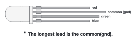
The longest leg connects to ground, the other legs connect to pins on your board with a 330 ohm resister between the led leg and the jumper wire to the board. Something like this:

If you're playing along at home, I connected the red leg to pin 12, the green leg to pin 13 and the blue leg to pin 16.
Test it out with some code
Before your setup function establish which color goes to which pins (change the numbers depending on which pins your legs are plugged into):
// LED pins
int RedPin = 12;
int GreenPin = 13;
int BluePin = 16;
In your set up function you'll need to set up the pins as outputs:
void setup() {
  // Set up RGB LED
  pinMode(RedPin, OUTPUT);
  pinMode(GreenPin, OUTPUT);
  pinMode(BluePin, OUTPUT);
}
Then in your loop function try turning on the various legs like this:
void loop() {
  // Turn LED Red
  digitalWrite(RedPin, HIGH);
  digitalWrite(GreenPin, LOW);
  digitalWrite(BluePin, LOW);
  // Wait one second
  delay(1000);

  // Turn LED Green
  digitalWrite(RedPin, LOW);
  digitalWrite(GreenPin, HIGH);
  digitalWrite(BluePin, LOW);
  // Wait one second
  delay(1000);

  // Turn LED Blue
  digitalWrite(RedPin, LOW);
  digitalWrite(GreenPin, LOW);
  digitalWrite(BluePin, HIGH);
  // Wait one second
  delay(1000);
}
That's it! That's all the hardware. Hopefully you're able to upload a basic blinky program to the ESP8266, you can read the correct temp and output it to serial and you can change the colors on your LED. Now we program!
Little guy in all its breadboardy glory:

I ended up adding buttons (see But Wait, There's More) so Kevin could adjust the upper and lower range himself without me needing to connect the device to the computer! Here it is in its final state without the ESP8266 and then with the ESP8266 so you can see the connections underneath it:


All I need to do now is build a permanent enclosure!
I learned a lot from this Internet of Things Experiment Guide from SparkFun. They have a lot of detail on ThingSpeak and IFTTT. I highly recommend reading through it. I'm going to refer back to it a lot here.
ThingSpeak is a free way to log data to the internet. With a little trickery you can have ThingSpeak trigger an IFTTT event if the data you're logging satisfies certain requirements. For instance, if the beer temp is too hot my program sends the number 1 to one of my fields. When that field logs a 1 instead of a 0 ThingSpeak tells IFTTT to send me a text. It also fetches the current temp and attaches that to the text. Pretty cool! Follow the directions on this page to set up ThingSpeak and get the right library. Then go to the next page and follow the directions for setting up your channel. Right now we need two fields - the Temperature field and one called Too Hot or something. The Too Hot field will be our trigger to text if the temp gets too hot. Triggers beyond that are up to you and what you need.
I recommend looking at the SparkFun tutorial's program and pulling out just what you need to log data - like a constant for now, since we're not using their temperature sensor - to ThingSpeak. Or the below code probably has everything you need to log a value to the first field of your ThingSpeak channel. Remeber to put in your own values for the WiFi and Channel parameters!!!
Set up your variables:
// Necessary libraries
#include <ESP8266WiFi.h>
#include "ThingSpeak.h"

// WiFi and Channel parameters
const char WIFI_SSID[] = "<YOUR WIFI SSID>";
const char WIFI_PSK[] = "<YOUR WIFI PASSWORD>";
unsigned long CHANNEL_ID = <THINGSPEAK CHANNEL ID>;
const char * WRITE_API_KEY = "<THINGSPEAK WRITE API KEY>";

// Pin definitions
const int LED_PIN = 5;

// Global variables
WiFiClient client;
Set up the LED, connect to Wifi and connect to Thingspeak:
void setup() {

  // Set up LED for debugging
  pinMode(LED_PIN, OUTPUT);

  // Connect to WiFi
  connectWiFi();

  // Initialize connection to ThingSpeak
  ThingSpeak.begin(client);
}
Set field one of your ThingSpeak to something, maybe the number 8, then send the data to ThingSpeak. Wait 20 seconds
void loop() {

  // Flash LED to show that we're sampling
  digitalWrite(LED_PIN, LOW);

  // Write the values to our ThingSpeak channel
  ThingSpeak.setField(1, 8); // <====== Change the number 8 to another value and see if it logs that
  ThingSpeak.writeFields(CHANNEL_ID, WRITE_API_KEY);

  // Turn LED off when we've posted the data
  digitalWrite(LED_PIN, HIGH);

  // ThingSpeak will only accept updates every 15 seconds
  delay(20000);
}
The function you need to connect to Wifi.
// Attempt to connect to WiFi
void connectWiFi() {

  byte led_status = 0;

  // Set WiFi mode to station (client)
  WiFi.mode(WIFI_STA);

  // Initiate connection with SSID and PSK
  WiFi.begin(WIFI_SSID, WIFI_PSK);

  // Blink LED while we wait for WiFi connection
  while ( WiFi.status() != WL_CONNECTED ) {
    digitalWrite(LED_PIN, led_status);
    led_status ^= 0x01;
    delay(100);
  }

  // Turn LED off when we are connected
  digitalWrite(LED_PIN, HIGH);
}
Fuss around with that until you can log data to ThingSpeak
IF This, Then That (IFTTT) is also free! If some requirement is satisfied, do something else. There are SO MANY triggers and things it can do in response. In our case, if we send a certain value to a field in ThingSpeak, it will send an HTTP request to IFTTT to send a text. The tutorial I've been referring back to has a page setting up IFTTT that sets up three buttons - one button sends an email, the second sends a text, the third sends a tweet, so the page is a little cluttered with all those instructions. You'll want to follow the directions for Button B.
Basically, set up an account at IFTTT, click your username then New Applet. Click on the big "+ this" then search for Webhooks and click that. Click the box "Receive a web request" as the trigger and name it something like "temp_too_hot". Click "Create trigger" then you'll go back to the "if this then that" screen. Click "+ that" and choose SMS as the action. Choose "Send me an SMS". In the message portion of the SMS action type something like "Temperature too hot! Temp: {{Value1}}". The {{Value1}} is where the temperature will be inserted later, so make sure it's typed exactly like that. Click Create Action and then Finish.
Scroll down the page until you see the heading "Find Your IFTTT Maker Channel Secret Key" to get your IFTTT secret key.
At ThingSpeak, click on Apps > ThingHTTP and click New ThingHTTP. This is what will contact the IFTTT applet we just made and send along our temp info. Give it a name (like, Temp Too Hot) and enter in a url. It will look like this: https://maker.ifttt.com/trigger/<IFTTT_APPLET_NAME>/with/key/<IFTTT_SECRET_KEY>. Replace <IFTTT_APPLET_NAME> with temp_too_hot or whatever you named your applet and obviously replace <IFTTT_SECRET_KEY> with the secret key you got from the step above. Mine looks like: https://maker.ifttt.com/trigger/out_of_range/with/key/xxxxxxxxxxxxxxxxxxxxxx The method should be POST and make sure to enter application/json in the Content Type field. In the body type {"value1":"%%channel_<YOUR_CHANNEL_ID>_field_1%%"} replacing <YOUR_CHANNEL_ID> with your own info. This will grab the first field from your channel and send it along to IFTTT as value 1. If you are copy/pasting make sure your quotes aren't stylized quotes!
On ThingSpeak, click Apps again, and then React, then click New React. This is what will check our data and see if it meets our requirements for a text. If so it will launch the ThingHTTP we made in the last step. Give it a name (Temp Too High), Condition Type is Numeric, Test Frequency is On Data Insertion. For the condition, choose the field 2 (the too high field) is equal to 1. For the action, perform ThingHTTP Temp Too Hot. I have it run this every time the condition is met, but you can set it to run only if the condition was previously false and now it's true.
Phew! That was a lot of work. Test it all out to see if it works. In the program we wrote earlier change the line ThingSpeak.setField(1, 8); to ThingSpeak.setField(1, 87); because 87 seems like a hot temp. Below that type ThingSpeak.setField(2, 1); which will send the value 1 to the second field. Remember this is our trigger field. If it equals 1 it's supposed to send us a text with the temp (87). Upload the program and let it run for a minute. You should get a few texts saying "Temp too hot! Temp: 87". Turn the board off so you don't get 5,000 texts! Make sure you get a text and it includes the temp. Change the 2 field line to ThingSpeak.setField(2, 0); and turn it on again, upload and make sure you don't get texts.
If that worked then you have a functioning connection between your program, ThingSpeak and IFTTT! Your program can now get on the WiFi and log data to the internet and text you if a condition is met. You can also get a temp reading using OneWire and DallasTemperature. And you can change the colors of an RGB LED. How you put all that together is mostly up to you and what you need from your program. I've tried giving you the building blocks for each element so you can modify it how you like. You can check out my beer_temp.ino file for exactly how I wrote mine. Hopefully it's commented enough so you can see what's going on. My program basically does the following:
- Connect to WiFi to communicate with the internet when needed
- Take a temperature reading
- Send the temperature to ThingSpeak so it can be accessed remotely over the internet
- Check if temperature is too high or too low. If it is, send a signal to ThingSpeak so to trigger IFTTT to send a text.
- Blink the LED blue if it's too cold, red if it's too hot and green if it's in the right range
- Wait until enough time has passed before taking another temperature reading.
WHY NOT TO - AND WHY TO - USE DELAY()
You might notice that when I blinked my LED I didn't use the delay() function. Instead I use millis() and created a variable to see how long ago it last blinked etc. Because if I delayed while blinking the program wouldn't check the temp. Why? this post does a great job of explaining it and explains the solution. I also ran the temp sensor checking loop with the same millis() logic, so the light could blink between checking the temp.
Another thing about delays is that you should build them into your program here and there. Maybe just a delay(100). SparkFun says it best here:
Delays allow the ESP8266 to perform critical tasks defined outside of the sketch. These tasks include setting up, and maintaining, a WiFi connection. Potentially infinite loops are generally dangerous. Add delays -- allowing the processor to perform other tasks -- wherever possible.
C++ IS NOT MY FIRST PROGRAMMING LANGUAGE
Or my second or third or fourth or 9th. Maybe somewhere around 15, I've lost count. In fact, I wouldn't even say that I know it. I just know enough other languages that I could figure out what I wanted to do. I'm 100% positive there are tighter, better ways to write my code. I can see ways to refactor my code and take out extra fluff but I'm leaving it as is so that it's clear to you - and me later - what each part does.
I hope you enjoyed that and if you're a n00b like I was you feel like you learned something. I'm still learning and I bet I got a few things wrong here and there, but all this worked for me so hopefully it can help someone else.
Originally the acceptable temperature range would get hardcoded into the program by me. When Kevin brews a new beer I would need to change the values in the program and upload it again. But once I finished programming it Kevin said he wanted to be able to adjust the upper and lower temperature ranges himself. The first 24 hours the beer will need to be in one range and then for several days after it will need to be in another. I thought about various ways to do that (like a remote server or Alexa skill) and decided to go with three buttons. I don't think I had enough pins left over to add an LCD screen so I had to get smart with how to do this so that it made sense without a screen, and I think I came up with a good solution.
During normal funciton the RGB LED slowly blinks blue, red, or green depending if the temp is too cold, too hot or just right. It glows solid purple while it's taking a temp and uploading it to the internet so you know it's busy. Here's where I changed things: the white button is the edit button - press it once and the LED rapidly flashes blue for a second then glows solid blue to let you know you're editing the lower range. Press the blue button to decrease the lower range by 1 degree and it flashes blue for a second as confirmation. Press the red button to increase the lower range by 1 and it flashes red for a second as confirmation. Press the edit button again and it flashes then glows red letting you know you're editing the upper range. Blue and red buttons work the same - blue button decreases upper range, red button increases it. Press the edit button again and the program leaves edit mode. Finishing the edit mode also triggers the program to take an immediate temp reading and will text you the new range values so you know if you set it right. I think the one LED does a pretty good job of communicating a lot of different states and actions.
You can see the code for the new version in the file beer_temp_with_buttons.ino
You can see a short video demo-ing it here