
I use a cheap 1610 CNC machine, KiCad, and Flatcam for milling PCBs, but remembering exactly which settings to use for each page in Flatcam for generating my milling gcode is a pain, and I occasionally mistype important values (they're almost all important!). This flatcam automation script is intended to eliminate that problem by taking my memory and observation skills out of the equation.
- Flatcam:
Betabranch (tested with 8.994)
Export your gerber & drill files:
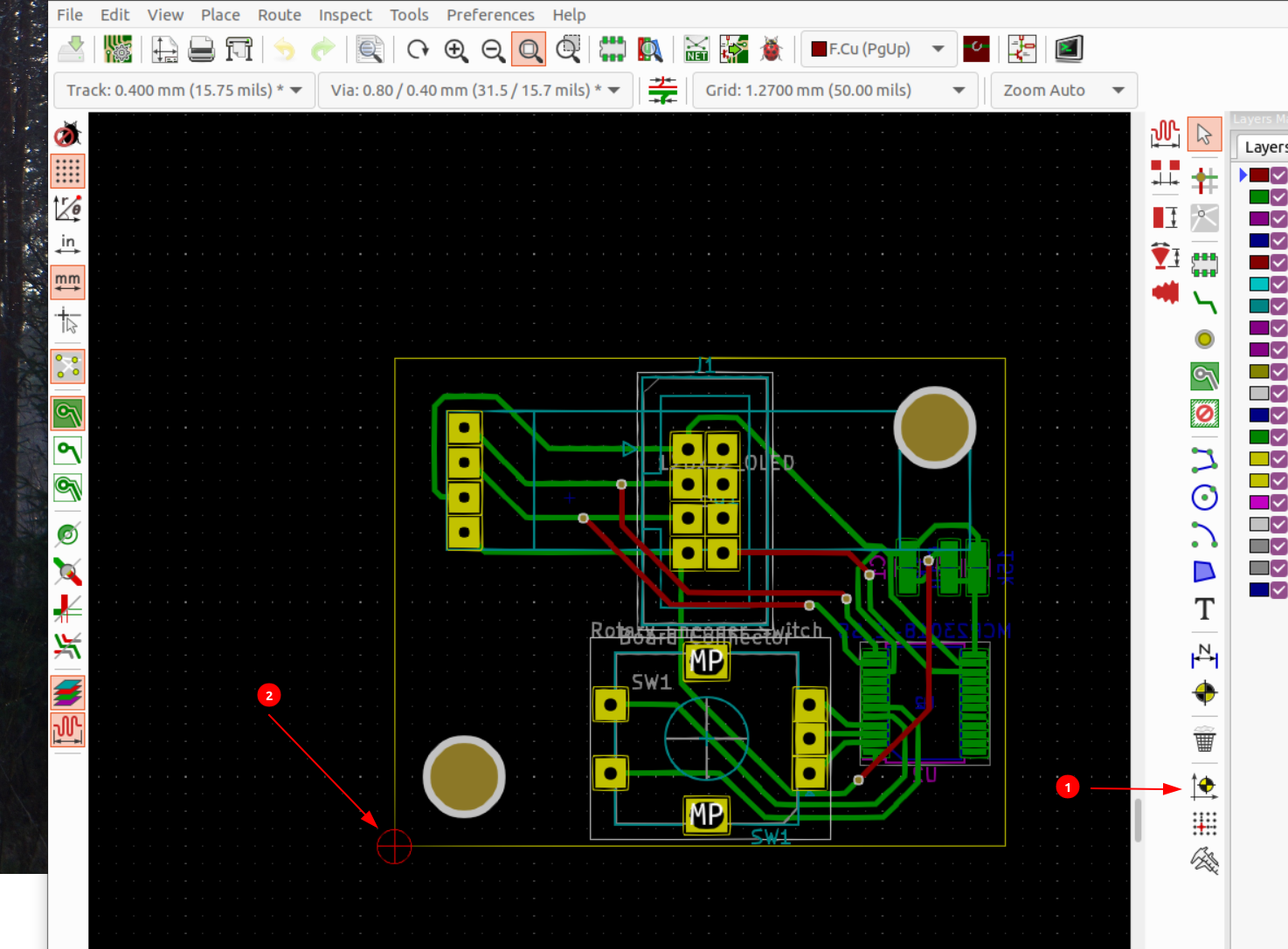
- Place the auxiliary axis for your board in the lower-left corner of
your board.
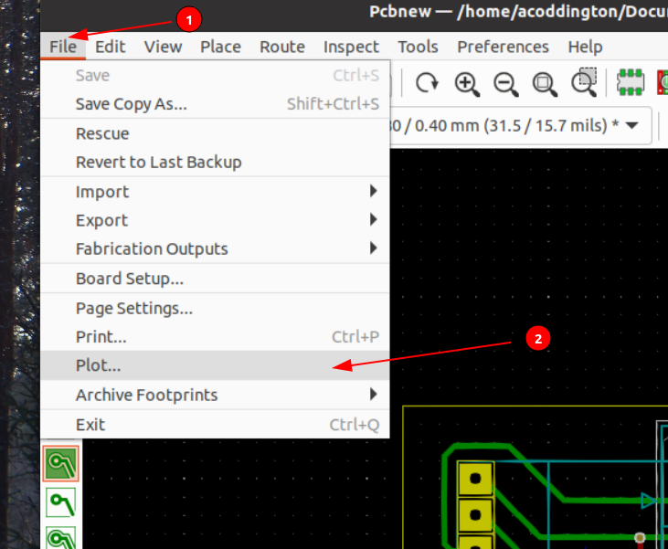
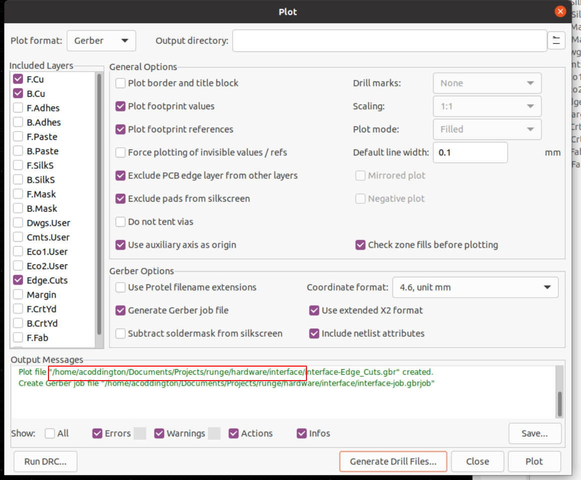
- Open the plot settings dialog from "File", "Plot".
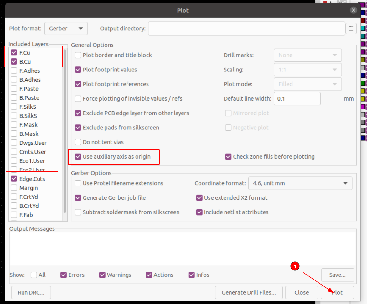
- Set plot settings as shown below, then click "Plot";
specifically make sure that you're:
- Plotting the F.Cu, B.Cu, and Edge.Cuts layers
- "Use auxiliary axis as origin" is checked.
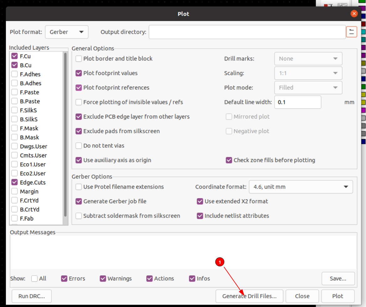
- Click the "Generate Drill Files..." button.
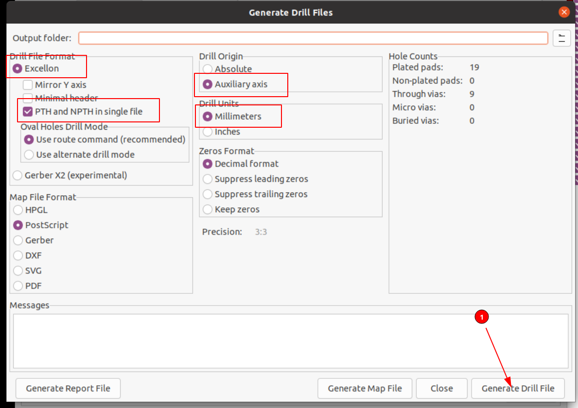
- Set the drill settings as shown below, and click "Generate drill file";
specifically make sure that you've set the following settings correctly:
- Exporting in the "Excellon" file format.
- "PTH and NPTH in a single file" is checked.
- Drill Origin is set to "Auxiliary axis"
- Drill Units is set to "Millimeters"
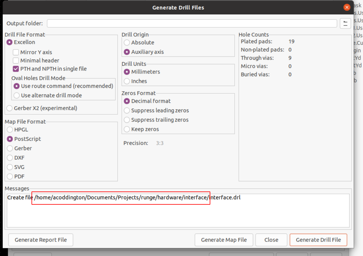
- Make note of the path to which these files were written for use below as
/path/to/gerber/exports. - Close the displayed dialogs.
Generate your flatcam script:
barbari build-script /path/to/gerber/exports simple
"simple" in the above string is the name of the milling configuration to use for the generated flatcam script. Alternative options exist -- see "Configuration" below for details.
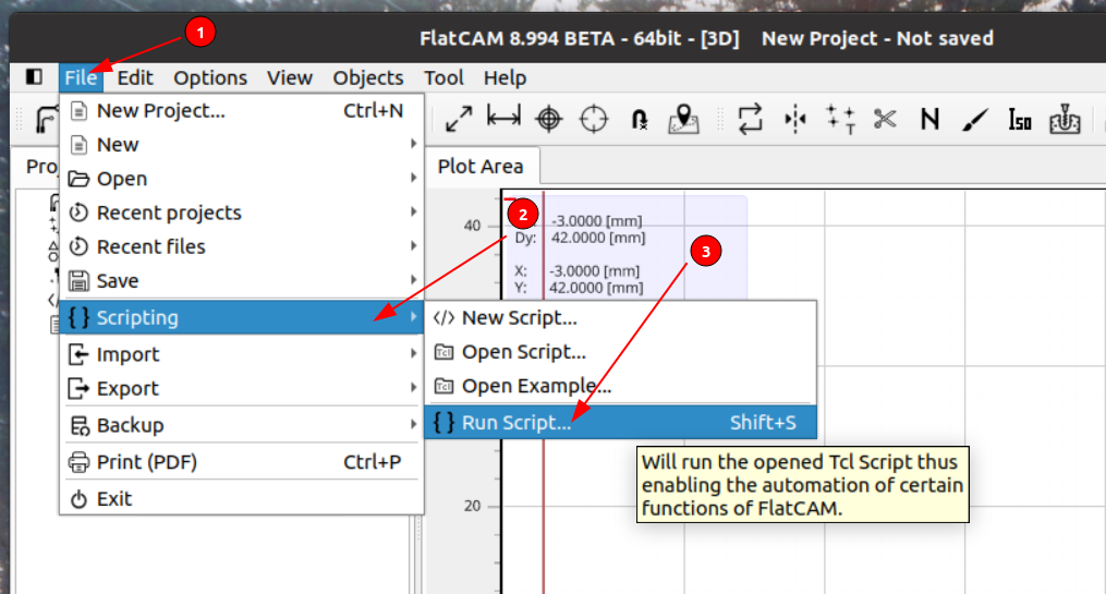
Run your script in flatcam:
- From Flatcam, open the "File", "Scripting", "Run Script".
- Select the script generated in
/path/to/gerber/exports.
Run your generated gcode in whatever tool you use for sending gcode to your mill. Note that the files will be stored in /path/to/gerber/exports and are expected to be run in the order indicated by their file names.
Roughly, the process is handled via the following steps:
- Milling Alignment holes (
alignment_holesin the configuration). These are used to allow you to perfectly flip your PCB for milling on both sides. - Isolation routing (
isolation_routingin the configuration). This will route your PCB's traces on both sides of the board. First, the back of your PCB (B.Cu) is routed, then the front (F.Cu). You'll want to flip over your board, using the drilled alignment holes in between these two steps. - Drilling (
drillin the configuration). - Milling slots (
slotin the configuration). - Edge cuts (
edge_cutsin the configuration). This is for cutting your PCB out of the larger piece of copper-clad board.
Barbari comes packaged with a couple milling profiles for two fairly conservative sets of milling operations; more than likely, the "simple" profile will be enough for you, but if it's not, you can either use one of the other packaged configuration settings (see list-configs and display-config to see their details) or create your own by exporting an example configuration and modifying it (see generate-config).
Note that Barbari configuration files can be layered atop one another by providing more than a single configuration file. Properties defined in later configuration files take precedence over properties in earlier ones, and drilling profiles are merged together.
Your configuration file is divided into multiple sections for the various steps of the milling process. Those sections are used for generating instructions for Flatcam.
Note that all properties use metric units -- usually millimeters unless specifically noted.
This is a short string describing this milling profile, and is used only for display in Barbari.
This is used to allow you to perfectly flip your PCB for milling on both sides.
Example:
alignment_holes:
  hole_size: 3.4
  hole_offset: 1
  tool_size: 1.5
  cut_z: -10
  travel_z: 2
  feed_rate: 100
  spindle_speed: 12000
  multi_depth: true
depth_per_pass: 0.2This is used to route the traces on your board.
Example:
isolation_routing:
  tool_size: 0.18
  width: 1
  pass_overlap: 1
  cut_z: -0.2
  travel_z: 2
  feed_rate: 200
  spindle_speed: 12000
  multi_depth: true
depth_per_pass: 0.1You probably don't have as many bits on hand as a PCB board house will; so these sections are here to allow you to group multiple drill sizes into sets of processes. For example, if you had only three bits -- a 0.4mm drill for vias, a 1.0mm drill for most through-holes, and a 1.0mm mill for everything bigger than that, you could have a section like this:
drill:
  via:
    max_size: 0.4
    specs:
      - type: cnc_drill
        params:
          tool_size: 0.4
          drill_z: -2.5
          travel_z: 2
          feed_rate: 50
          spindle_speed: 12000
  drilled:
    min_size: 0.4
    max_size: 1.0
    specs:
      - type: cnc_drill
        params:
          tool_size: 1.0
          drill_z: -2.5
          travel_z: 2
          feed_rate: 50
          spindle_speed: 12000
  milled:
    min_size: 1.0
    specs:
      - type: mill_holes
        params:
          tool_size: 1
          cut_z: -2.5
          travel_z: 2
          feed_rate: 100
          spindle_speed: 12000
          multi_depth: true
          depth_per_pass: 0.2
You'll see from the above that any holes up to 0.4mm in diameter will be drilled using the via processes (called specs here) -- drilling with a 0.4mm drill, any drills from 0.4mm to 1.0mm in size will be drilled using a 1.0mm drill bit, and anything bigger than 1.0mm will be milled using a 1.0mm end mill. You might
notice that some drill bit sizes match multiple specs -- that's fine -- barbari
will choose the best process for each particular tool algorithmically.
In some situations -- mostly around drilling large holes -- you might need a particular range of drill sizes to be drilled more than once. For example, the included drilling profile for using voltera 1mm rivets for plated through-holes looks like this:
  pth:
    min_size: 0.4
    max_size: 1.1
    specs:
      - type: cnc_drill
        params:
          tool_size: 0.7
          drill_z: -2.5
          travel_z: 2
          feed_rate: 50
          spindle_speed: 12000
      - type: cnc_drill
        params:
          tool_size: 1.5
          drill_z: -2.5
          travel_z: 2
          feed_rate: 50
          spindle_speed: 12000
The above configuration will drill any holes from 0.4mm to 1.1mm in diameter twice -- first with a 0.7mm drill, and then afterward with a 1.5mm drill.
The slot section defines job parameters for milling slots in your PCB (i.e. non-round holes). It follows exactly the same pattern used for drill above.
You probably won't be using an entire sheet of copper-clad board for your board. This section defines how to cut your newly-milled PCB out of the copper-clad.
This section is special, and is used for including other configuration files into the configuration file. It is a list of strings that can be either:
- A relative (to the configuration file) path to a different configuration file to include. This must end in
.yamlor.yml. This is the method to use if you would not like user-level configurations to override the pre-packaged ones. - The name of a configuration to use. See
list-configs --allfor a list of configuration files. This is the method to use if you would like user-level configurations to override the pre-packaged ones.
For example, this is the "rivets" configuration:
description: |
  The standard configuration @coddingtonbear
  uses when milling his PCBs.  This uses
  copper wire vias, 10mm deep alignment holes, [voltera 1mm rivets](https://www.voltera.io/store/consumables/rivets-1-0mm)
  for holes near 1mm, and milled holes
  larger than 1.1mm.
include:
  - ./default_isolation_routing.yaml
  - ./default_alignment_holes.yaml
  - ./copper_wire_vias.yaml
  - ./drilled_pth_04_11.yaml
  - ./milled_11.yaml
  - ./default_edge_cuts.yaml