An FTDI FT2232H-based multi-protocol tool for hardware hacking.
There are plenty of -232H series breakout boards, but they are generally designed to be an easy way to adapt it to a specific use, and not designed for regularly plugging in to all different target systems.
The two exceptions are the Exodus Intellegence Hardware Interface Board which is not open hardware or commercially available, and TIMEP which is the origin and heritage of this project.
In general, Tigard was designed to work as-is with several tools and lbraries that already support the x232H family of chips. This includes:
- USB-Serial drivers for UART access
- OpenOCD and URJTAG for JTAG
- Flashrom, libmpsse, pyftdi and other tools for SPI interfaces
- libmpsse and pyftdi for I2C interfaces
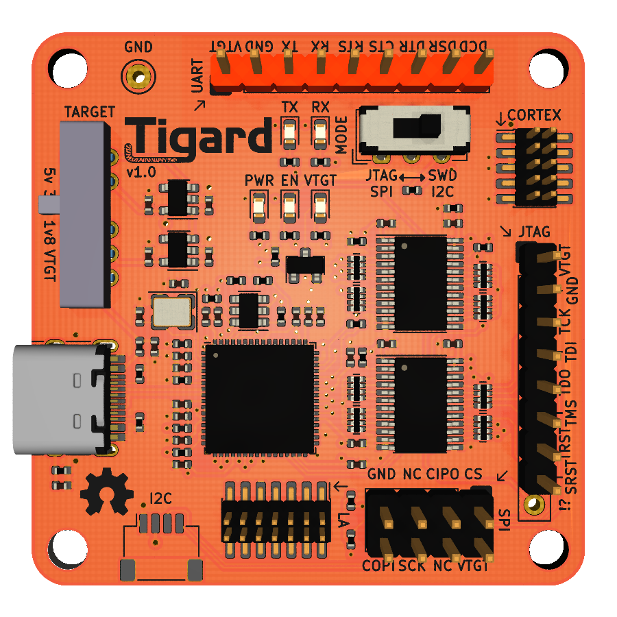
Highlights:
- Dual-port, with one dedicated to UART and the second shared with other interfaces
- High-performance directional level shifters for 1.8 to 5.5v operation
- Switch to choose between on-board 1.8, 3.3, and 5.0v supplies and vTarget
- Switch to choose between SPI/JTAG and I2C/SWD modes
- Logic analyser port to observe device-level signals (v1.0 and later)
- Indicator lights to aid debugging
Starting with the board completely disconnected:
- Connect board to target system with clips or jumper wires
- Select the correct mode either SPI/JTAG or SWD/I2C
- Ensure that the voltage switch is in VTGT mode
- Plug in the USB cable. The PWR and EN LEDs will illuminate
- Power on your target.
- If you connected VTGT to your target, the VTGT LED will illuminate. If not, you can now select your voltage with the voltage switch
There are two switches on Tigard to set the mode of operation. One controls voltage, one controls how several of the IO pins are wired. Both need to be set properly for a specific use mode. Details are in each of the interface sections further below, but here is a summary of the modes and their uses:
This switch chooses the reference voltage for the level shifters and the target system:
- 1V8, 3V3, and 5V all apply a voltage to the VTGT pin.
- VTGT disconnects the VTGT pin from supplies, and depends on the wire connected to the target to set the level shifter voltage.
This results in 3 distinct use cases:
- Target-Powered: Set the switch to VTGT and connect the VTGT wire to the powered target. The target powers the level shifters.
- Tigard-Powered: Set the switch to a voltage, and connect the VTGT to the unpowered target. Tigard supplies power to the target.
- Self-Powered: Set the switch to a voltage, but do NOT connect the Vtgt wire. Tigard powers its own level shifters. Target powers itself.
This switch controls how some of the I/O pins are connected for specific uses:
- When set to JTAG/SPI mode:
- All signals run straight through
- CORTEX and JTAG headers are wired for normal JTAG
- JTAG and SPI headers can be used for SPI
- When set to SWD/I2C mode:
- DO and DI are wired together to create SWDIO or SDA
- CORTEX and JTAG headers can be used for SWD
- JTAG and SPI headers can be used for I2C
- In most cases, you need pins 2,3,and 4 of the UART header - Ground, TX, and RX. Connect these to your target
- If you have a VCC header on your target, connect pin 1 - VTGT to it, and slide the voltage selector to VTGT
- If you don't have a VCC header, leave the VTGT wire disconnected, and choose your target voltage with the selector
The first of the two ports is connected to the UART header. When you plug Tigard in, you will see two serial devices show up - the first one is the one you want. Start your software using the appropriate serial port. For example:
screen /dev/ttyUSB0 115200The SPI/I2C header is laid out to be the same orientation as the pins on a standard 8-pin SPI flash chip, making it easy to attach clips or sockets.
- Select SPI/JTAG on the mode selection switch
- Connect your clip or socket to the header. Pay attention to pin 1, which is usually marked on sockets or has a red/highlighted wire on ribbon cables
- Connect your clip to the target or insert your chip into the socket
- If you're doing this in-circuit, you must take extra precautions to make sure no other device is communicating with the SPI device.
- If you're using a clip in-circuit and the target is powered on, choose the VTGT option on the voltage slider
- If you're using a zif socket, or clip with a powered-off target, choose the voltage on the voltage slider.
flashrom is the most common tool for SPI flash dumps. However, while pervasive, it is very slow and inefficient.
flashrom -p ft2232_spi:type=2232H,port=B,divisor=4libmpsse is a powerful library for controlling the MPSSE, or high speed serial pins of the x232H series. However, it is no longer recommended because of a large number of dependencies
pyftdi is a new and simple interface very similar to libmpsse:
from pyftdi.ftdi import Ftdi
Ftdi.show_devices()
from os import environ
ftdi_url = environ.get('FTDI_DEVICE', 'ftdi://ftdi:2232:1:23f/2')
from spiflash.serialflash import SerialFlashManager
flash=SerialFlashManager.get_flash_device(ftdi_url)
print("Flash device: %s @ SPI freq %0.1f MHz" % (flash, flash.spi_frequency/1E6))
f=open("data.bin","wb")
f.write(flash.read(0,len(flash)))
f.close()The I2C header (on hardware versions 1.0 and later) is compatible with Sparkfun's Qwiic and Adafruit's STEMMA QT system:
- Connect a 4-pin JST SH compatible cable into the I2C connector
- Connect the other end to your STEMMA QT, Qwiic, or other I2C device
In addition, the SPI header is laid out to be the same orientation as the pins on most 8-pin I2C chips, making it easy to attach clips or sockets:
- Connect your clip or socket to the header. Pay attention to pin 1, which is usually marked on sockets or has a red/highlighted wire on ribbon cables
- Connect your clip to the target or insert your chip into the socket
In either case, you need to set the Tigard switches properly:
- Select I2C on the mode selection switch
- If you're attaching to a device in-circuit and the target has its own power, choose the VTGT option on the voltage slider
- If you're attaching a standalone sensor, socket, or clip with a powered off target, choose the correct voltage on the voltage slider
The FT2232H has a very limited I2C implementation. I2C depends on shared I/O lines using common emitter instead of push-pull-tristate I/O, but the FT2232H doesn't support common emitter. Therefore:
- Only controller operation is supported, not Device
- Tigard may not play nice if there are other controllers present on the I2C interface
- Clock stretching is not supported
- The I2C switch ties the DI and DO lines together so that it can do bidirectional communication
- The pullup resistors are not included since they are usually located on the target, and the weak pullups on the level shifters are sufficient
To accomodate both I2C and SWD, the DI and DO lines are combined through resistor R16. This is required for SWD and acceptable for I2C. For the best I2C performace with the tradeoff of breaking SWD functionality, bridge the HACK solder jumper on the bottom. This will bypass resistor R16, shorting DI and DO when the MODE switch is set to SWD/I2C.
Many I2C targets already have pullup resistors. In addition, all of Tigard's I/O pins have a weak 100K ohm pullup. In testing, this has been sufficient for both in-circuit and external use of most I2C devices. If you need stronger pullups on I2C, you can temporarily add them by pulling up COPI and SCK on the SPI header, or TCK and TDI on the JTAG header.
libmpsse is a powerful library for controlling the MPSSE, or high speed serial pins of the x232H series. However, it is no longer recommended because of a large number of dependencies
pyftdi is a new and simple interface very similar to libmpsse:
from pyftdi.ftdi import Ftdi
Ftdi.show_devices()
from os import environ
ftdi_url = environ.get('FTDI_DEVICE', 'ftdi://ftdi:2232:1:23f/2')
from i2cflash.serialeeprom import SerialEepromManager
flash = SerialEepromManager.get_flash_device(ftdi_url,'24AA32A',0x50)
flash.write(5,10)
flash.read(0,32)The JTAG header is laid out with pins in the same order as the FTDI I/O pins are labeled, in order to be consistent with many other x232H breakout boards.
In additon, the CORTEX header is also wired as a standard ARM 10-pin JTAG header.
Be sure to select JTAG on the mode selection switch. This makes sure that TDI and TDO are separated, and ensures that TMS is wired properly to the CORTEX header. Otherwise, the standard hookup sequence applies.
OpenOCD is a powerful tool for On-Chip Debugging of ARM, MIPS, and some other architectures.
The appropriate configuration file (make this a link to the file) should look like:
interface ftdi
ftdi_vid_pid 0x0403 0x6010
ftdi_channel 1
adapter_khz 2000
ftdi_layout_init 0x0078 0x017b
ftdi_layout_signal nTRST -ndata 0x0010 -noe 0x0040
ftdi_layout_signal nSRST -ndata 0x0020 -noe 0x0040
transport select jtag
To use it with openocd:
openocd -f tigard-jtag.cfgThe SWD header a standard 10-pin header found on many SWD target boards. A short 'SWD' cable with the same header on both ends is the ideal way to hook up to most targets.
You can also use the TCK(for SWCLK) and TDI(for SWDIO) pins of the JTAG header if you need a 2.54mm jumper-friendly connection to an SWD target.
Be sure to select SWD on the mode selection switch. This connects the DI and DO pins with resistor R16 to make the bidirectional SWDIO pin, and connect it to pin 2 of the CORTEX header. Otherwise, the standard hookup sequence applies.
OpenOCD is a powerful tool for On-Chip Debugging of ARM, MIPS, and some other architectures. In order to use it for SWD with Tigard, you'll need to build it from source. The directions from the AND!XOR DC27 Badge cover it step-by-step.
The appropriate configuration file (make this a link to the file) should look like:
adapter driver ftdi
transport select swd
ftdi_vid_pid 0x0403 0x6010
ftdi_channel 1
adapter speed 2000
ftdi_layout_init 0x0018 0x05fb
ftdi_layout_signal SWD_EN -data 0
ftdi_layout_signal nSRST -ndata 0x0020 -noe 0x0040
To use it with openocd:
openocd -f tigard-swd.cfgThe Lattice iCE40 family of FPGAs are popular for small scale projects because of their low cost and the availability of an open toolchain. While this is a very specific target, Tigard is well suited for programming devices since it has all the necessary pins readily available.
All the necessary pins are on the JTAG header. The bonus "!?" pin is not populated by default. The JTAG !? pin and the UART RX pin are shorted in case you need to flash an iCE40 but don't want to solder your Tigard. See the pinouts table below for details.
Be sure to select JTAG/SPI on the mode selection switch. This makes sure that COPI and CIPO are separated.
If you are planning on programming SRAM instead of FLASH:
- Swap COPI and CIPO
- Disconnect CS from your FLASH, but leave it attached to the iCE40.
To program your target's nonvolatile FLASH, use iceprog:
iceprog -I B yourbitstream.bin
If you prefer to directly program the ice40's SRAM, make sure you adjust your wiring and again use iceprog:
iceprog -I B -S yourbitstream.bin
Remember that if you choose to program the SRAM, your bitstream will be lost on power cycle.
This will turn on when the board has USB power and should turn on immediately when the USB cable is connected.
- If it does not, then check your USB cable and power supply.
- If it comes on then goes off, is dim, or flickers, then you have likely shorted power or ground somewhere with your wires or your target.
This will turn on when the FTDI chip is operation and should turn on a moment after the usb power LED is on.
- If it does not come on, you may have a faulty USB cable, a power-only USB port or cable, or a bad FTDI chip
This will turn on when the level shifters are properly powered, either by your target or by the onboard level selector
- If you are in VTGT mode, and it does not come on, check your target power and your power and ground wiring to the target
- If you are selecting a voltage and it does not come on, you have likely shorted power or ground somewhere with your wires or target.
- There are corner cases where VTGT will get latched to a voltage applied to an output pin. Establishing a habit of always starting with VTGT off will help avoid this.
When all LEDS are on, then Tigard is probably working as intended. If you are still having trouble, there are a few possibilities. They are listed in order of likelihood, though it makes sense to test the easier cases first:
- It's a wiring issure. Make sure your wires are connected well. Confirm with a multimeter.
- It's a target issue. Try a different target to make sure your software is working properly
- It's a software issue. Try a different software tool or mode to make sure your board works properly
- It's a protocol issue. Observe your signals with a logic analyzer or oscilloscope to make sure they're correct
- It's a hardware issue. Try a different Tigard board to see if it persists
- It's a tigard issue. Try a different x232H board to see if it persists
There are way too many choices of 'standard' pinouts for all of these interfaces. Pinouts were chosen for ease of use, specificially:
- If there's a well established and used standard, use it (SWD)
- If there's a predominant primary usage that would be easier, use it (SPI/I2C)
- If there are other common boards with pinouts, use them (UART and JTAG)
This pinout prioritizes putting the FT2232H pins in sequential order - similar to many x232H breakout boards
The coloring of the wiring harness is intended to match most common usb-serial cables
| Pin Number | UART Signal | Color | FT2232H Pin |
|---|---|---|---|
| 1 | VTGT | Red | -- |
| 2 | GDD | Black | -- |
| 3 | TX | Green | AD0 |
| 4 | RX | White | AD1 |
| 5 | RTS | -- | AD2 |
| 6 | CTS | -- | AD3 |
| 7 | DTR | -- | AD4 |
| 8 | DSR | -- | AD5 |
| 9 | DCD | -- | AD6 |
This is a standard pinout. In order to accomodate both SWD and JTAG, the mode switch:
- Combines DI and DO to create SWDIO for SWD mode
- Selects between SWDIO and TMS for pin 2
| Pin Number | SWD Signal | FT2232H Pin | JTAG Signal | FT2232H Pin |
|---|---|---|---|---|
| 1 | VTGT | -- | VTGT | -- |
| 2 | SWDIO | BD1 BD2 | TMS | BD3 |
| 3 | GND | -- | GND | -- |
| 4 | SWDCLK | BD0 | TCK | BD0 |
| 5 | GND | -- | GND | -- |
| 6 | NC | -- | TDO | BD2 |
| 7 | KEY | -- | KEY | -- |
| 8 | NC | -- | TDI | BD1 |
| 9 | GND | -- | GND | -- |
| 10 | nSRST | BD5 | nSRST | BD5 |
This pinout prioritizes putting the FT2232H pins in sequential order - similar to many x232H breakout boards.
In general, set the mode switch to SPI/JTAG mode when using this connector.
The coloring of the wiring harness is what SecuringHardware.com used for their Adafruit FT232H wiring harness for several years. The colors were chosen because frequently black-brown-red-orange are used with logic analyzers in class, so unique colors were chosen for this wiring harness.
This header can also be used for I2C and SPI if the 8-pin header doesn't make sense in your application.
| Pin Number | JTAG Pin | Color | FT2232H Pin |
|---|---|---|---|
| 1 | VTGT | Red | -- |
| 2 | GND | Black | -- |
| 3 | TCK | White | BD0 |
| 4 | TDI | Grey | BD1 |
| 5 | TDO | Purple | BD2 |
| 6 | TMS | Blue | BD3 |
| 7 | TRST | Green | BD4 |
| 8 | SRST | Yellow | BD5 |
This header is designed specifically to match the pinout of most 8-pin SPI and I2C chips, so that a jumper to a chip clip or a socket would align properly.
In order to accomodate both SPI and I2C, the mode switch:
- Combines DI and DO to create SDA for I2C mode
- Disconnects pin 2 in I2C mode for devices that use it as an address signal
| Chip Pin Number | Header Pin Number | SPI signal | FT2232H Pin |
|---|---|---|---|
| 1 | 1 | CS | BD3 |
| 2 | 3 | CIPO | BD2 |
| 3 | 5 | WP | pullup |
| 4 | 7 | GND | -- |
| 5 | 8 | COPI | BD1 |
| 6 | 6 | SCK | BD0 |
| 7 | 4 | EN | pullup |
| 8 | 2 | VTGT | -- |
Often it is necessary to debug a protocol with a logic analyzer. The LA port is best suited to monitoring push-pull signals where Tigard is an intended driver or receiver. It's tested and working well with UART, SPI and JTAG, and generally works with I2C. The expected use case is that you are using Tigard to communicate with a target, but need to debug that communication.
The LA port may be used as a passive mechanical adapter although this usage is not supported. For best results, power the Tigard board but disconnect VTGT from the target. Additional effort will likely be required to ensure signal integrity
This header is specifically designed to connect directly to the Bitmagic logic analyzer, or you could use the Bitmagic logic analyzer wiring harness to connect to any other tool.
The 8 most interesting signals are connected - 6 from the JTAG/SWD/SPI/I2C port, and 2 from the UART port.
| Pin Number | Bitmagic Signal | FT2232 Pin | JTAG signal | SPI signal | SWD Signal | I2C Signal | UART Signal |
|---|---|---|---|---|---|---|---|
| 1 | xPB0 | BD0 | TCK | SCK | SWCLK | SCL | |
| 2 | xPB1 | BD1 | TDI | COPI | SWDIO | SDA | |
| 3 | xPB2 | BD2 | TDO | CIPO | SWDIO | SDA | |
| 4 | xPB3 | BD3 | TMS | CS | |||
| 5 | xPB4 | BD4 | TRST | ||||
| 6 | xPB5 | BD5 | SRST | ||||
| 7 | xPB6 | AD0 | TX | ||||
| 8 | xPB7 | AD1 | RX | ||||
| 9 | GND | ||||||
| 10 | GND | ||||||
| 11 | xTRIG | ||||||
| 12 | xCLK | ||||||
| 13 | xTRIG2 | ||||||
| 14 | xIFCLK |
This header is designed specifically to match Sparkfun's Qwiic and Adafruit's STEMMA QT system.
Set the mode switch to I2C/SWD mode when using this connector.
| Pin Number | I2C signal | FT2232H Pin |
|---|---|---|
| 1 | GND | --- |
| 2 | VCC | --- |
| 3 | SDA | BD1 and BD2 |
| 4 | SCL | BD0 |
Use the JTAG header with the addition of the "!?" pin which is not populated by default.
| Pin Number | Label | iCE40 Signal | FT2232 Pin |
|---|---|---|---|
| 1 | VTGT | VTGT | --- |
| 2 | GND | GND | --- |
| 3 | TCK | CLK | BD0 |
| 4 | TDI/MOSI/SDA | MOSI/COPI | BD1 |
| 5 | TDO/MISO/-- | MISO/CIPO | BD2 |
| 6 | TMS/SS/-- | --- | --- |
| 7 | TRST/--/-- | CS/ICE_SS_B | BD4 |
| 8 | SRST/--/-- | CRESET | BD5 |
| 9 | !? | CDONE | BD6 |
JTAG !? pin and the UART RX pin are shorted in case you need to flash an iCE40 but don't want to solder your Tigard.
Tigard follows a convention for allocating serial numbers. If you decide to make and sell your own Tigards, please change the first two characters "TG" to something else.
Format: TGMmxxxx
TG- constant indicates "tigard"M- major version decimal numberm- minor version decimal numberxxxx- 0 padded lowercase hex serial starting at 0
- First batch of 28 (Jul 5, 2020): TG010000 - TG01001b
- Second batch of 42 (Aug 5, 2020): TG01001c - TG010046