TheFinalChessCard Replica
TheFinalChessCard for C64/C128, replicated using SprintLayout. Here are the sprint and gerber files.
The scanned images are from the World of Jani blog article about this card. See also the forum64.de threads.
- http://blog.worldofjani.com/?p=3460
- https://www.forum64.de/index.php?thread/73757-the-final-chesscard/
preview images from SprintLayout
The Replica 1.0 prototype
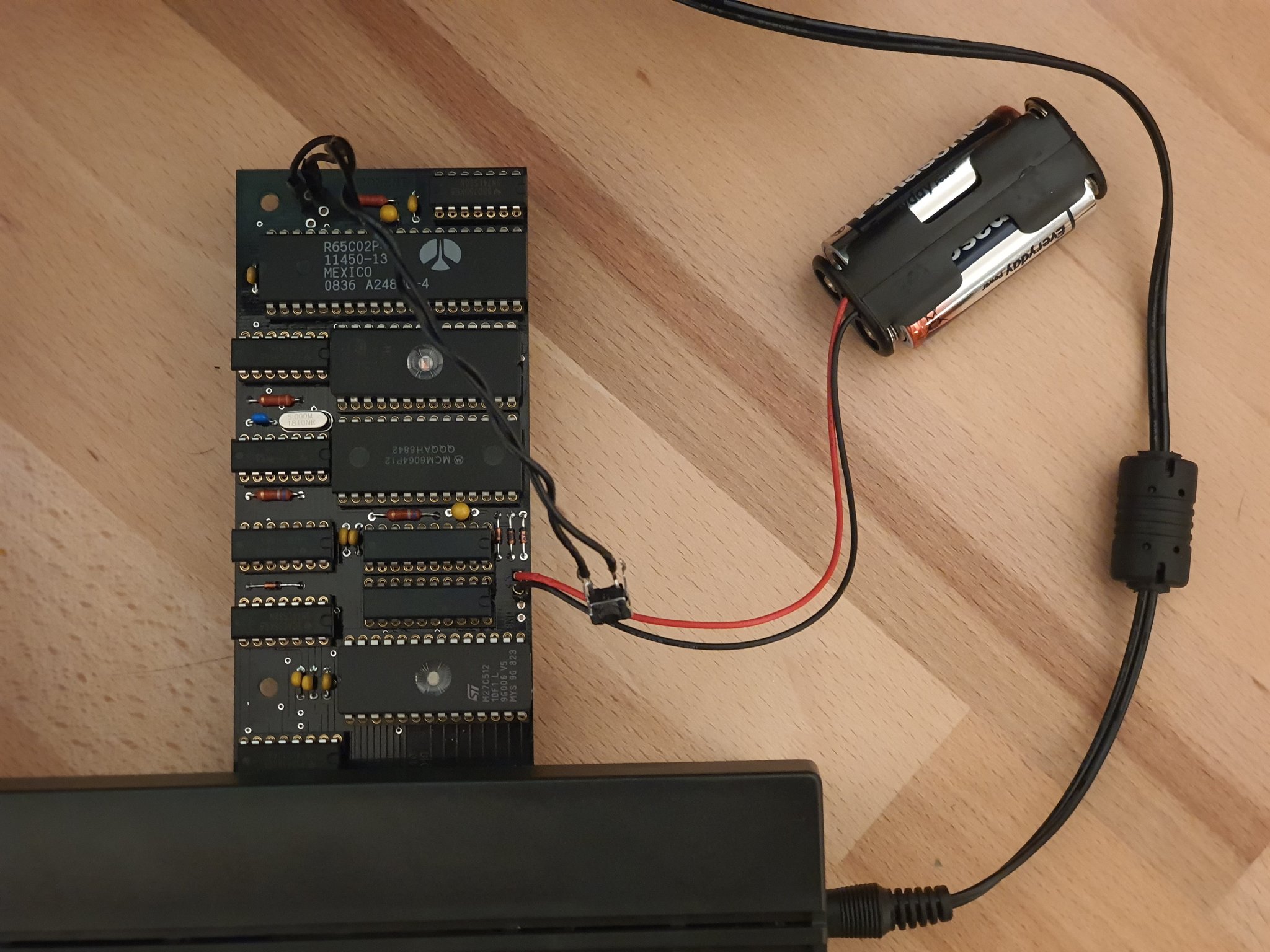
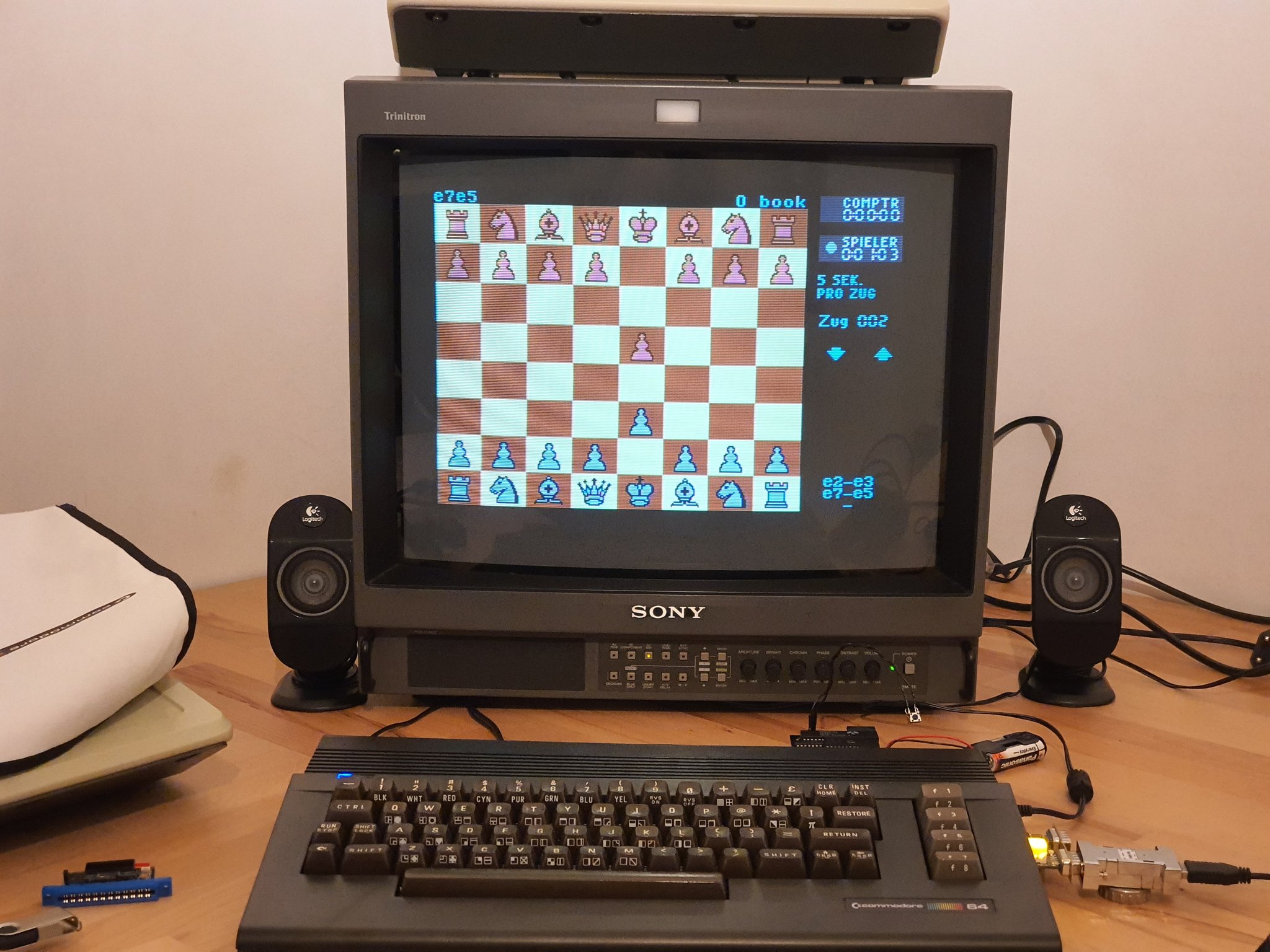
The PCB Rev 1.0 has been prototyped by Amon_RA on twitter. Thank you so much! Here are two images from his setup:
| Image 1 | Image 2 |
|---|---|
 |
 |
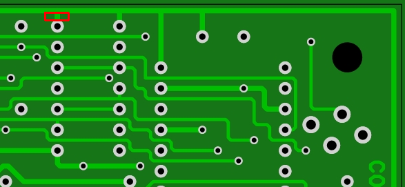
The Rev 1.0 had a grounded READ pin near the top edge. To find it look at the 74LS32 closest to the CPU, pin 8. If you have Rev 1.0, cut this trace betwen pin8 and GND at top edge. This is fixed in Rev 1.1
I would also like to thank the work by lvr for the schematics draft he posted in a forum64.de thread. With this schematic I was able to match my gerbers against a netlist generated from his schematics, and in this way the error in Rev 1.0 was easy to spot. The draft was very close to the layout. Thanks also to @thilographie_de for hunting the error with me.
Links
After doing the C64 KU-motherboard and the videoseries, I still hadn't shown my viewers how I went from images to gerber files. This is where I got the motivation for doing this TFCC replica. I made two videos. The first video got linked on Jani's website and also ended up in an article about it on hackaday called Reverse Engineer PCBs With SprintLayout. :-)
Change log
- 2020-01-25 Rev 1.1:
- pin 8 "READ" on 74LS32 (near CPU) was grounded. Removed GND.
- A trace stopped too early before a via. Still connected. Fixed.
- 2019-12-31 Rev 1.0: Touched up traces on a finer grid. 45degree bends.
- shown in video: traced up. quick 90 degree bends
TheFinalChessCard KiCad (modified replica)
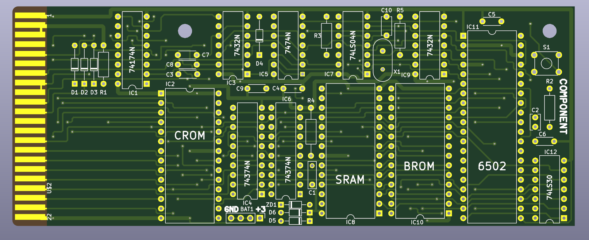
The replica above I'd like to be .. a replica. Some changes are desired. In this KiCad version we have moved two ICs back onto the grid. They were just too close for IC sockets. A zener diode was also too close to the same ICs. The crystal touched some metal. The power rails were thin. I have solved the changes in this version. The schematics were drafted by lvr as mentioned above regarding the PCB Rev 1.0.
Gerbers are available. Look under the KiCad folder.
Change log
The KiCad version branches off from the replica 1.1 board, hence why it is called 1.1.K1 where K is KiCad :)
Note that this version has never been prototype. Use at own risk if you decide to do so!
- 2020-01-26 Rev 1.1.K1:
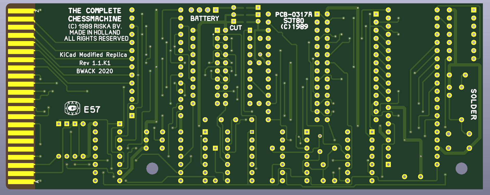
- Silkscreen artwork
- Thicker power traces (0.63. -> 1mm)
- Better space between two ICs. Moved some components to satisfy Cortyard errors.
- New reset button. Standard 5x5mm push button.
