The goal of this project was to create a more adanced lane finding pipeline to process video streams.
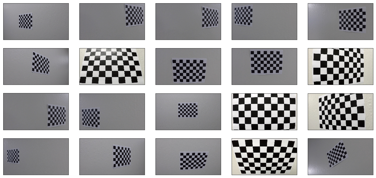
The lenses of recording devices introduce radial and tangenital distortions to the imagery they collect. This is also the case with this project's road imagery. To correct for that, I used twenty images of the same chessboard taken from various angles (with the same lense as that used in the vehicle). This is a common technique for camera calibration due to the standardization of chessboard dimensions.
Having chessboard images, I started by preparing (x, y, z=0) coordinates of chessboard corners (interior ones where black and white squares meet at their corners). Thus, obj_p is just a replicated array of coordinates, and obj_points will be appended with a copy of it every time I successfully detect all chessboard corners in a test image. img_points will be appended with the (x, y) pixel position of each of the corners in the image plane with each successful chessboard detection.
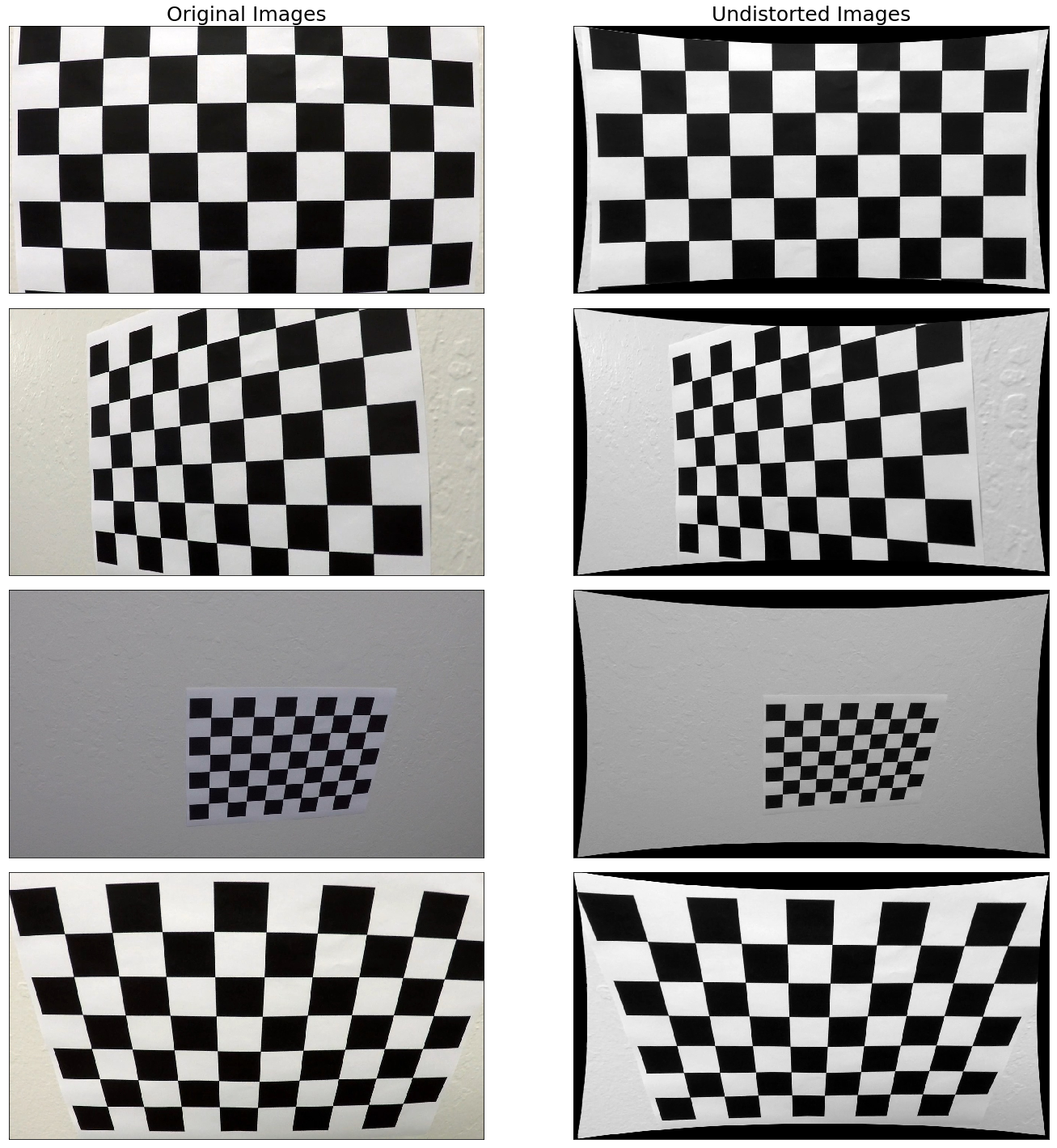
I then used the output obj_points and img_points to compute the camera calibration and distortion coefficients using the cv2.calibrateCamera() function. I applied this distortion correction to the test image using the cv2.undistort() function and obtained this result:
The code for this can be found in utils.calibration.calibrate_camera() (lines 86-108).
Now, I will go over the steps in the pipeline itself.
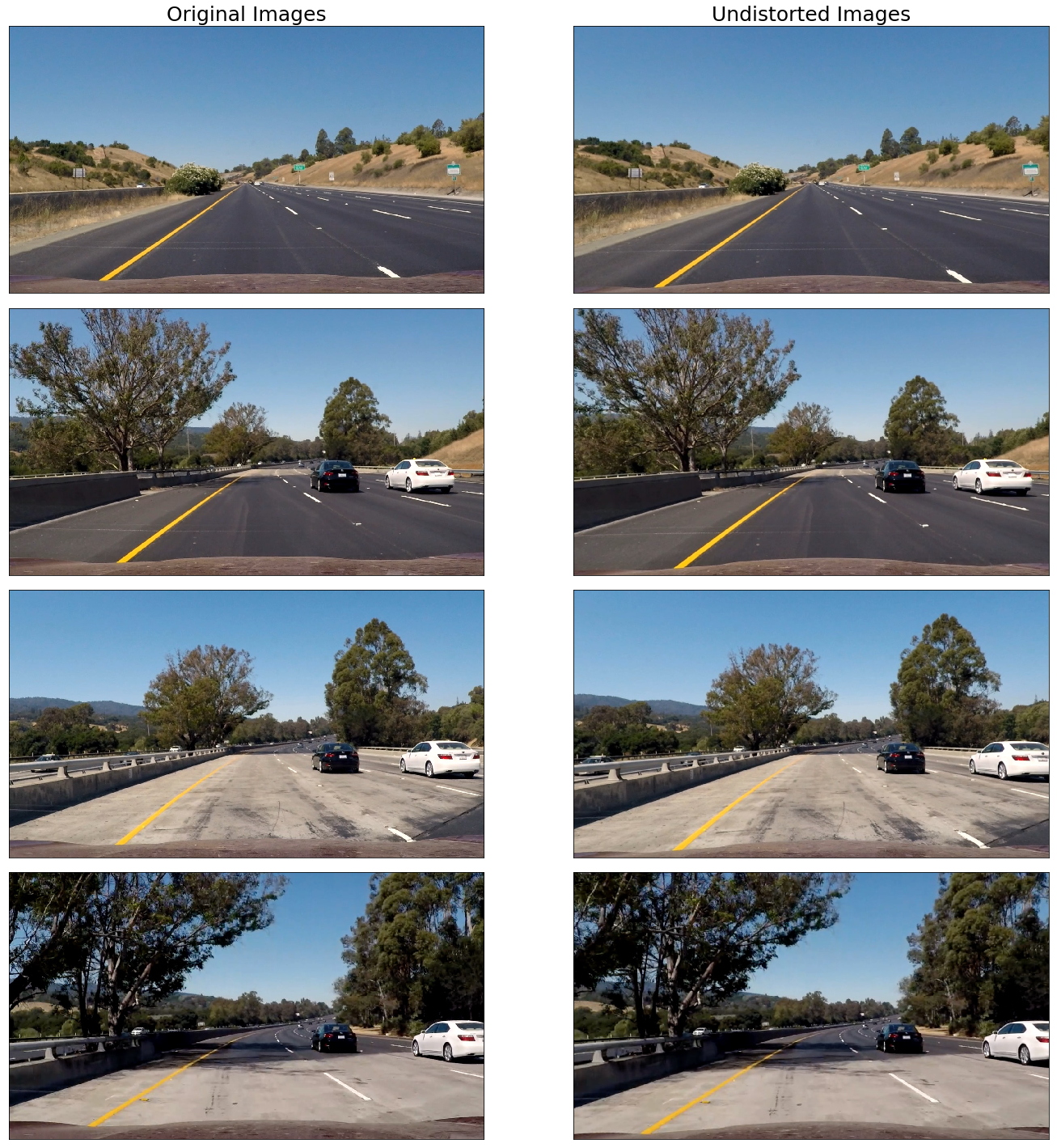
As explained in the camera calibration discussion, the very first step is to undistort the camera imagery. Using the camera calibration and distortion coefficients derived from the chessboard imagery, I undistort all camera images using utils.calibration.undistort_imgs() (lines 120-134). The results are provied below.
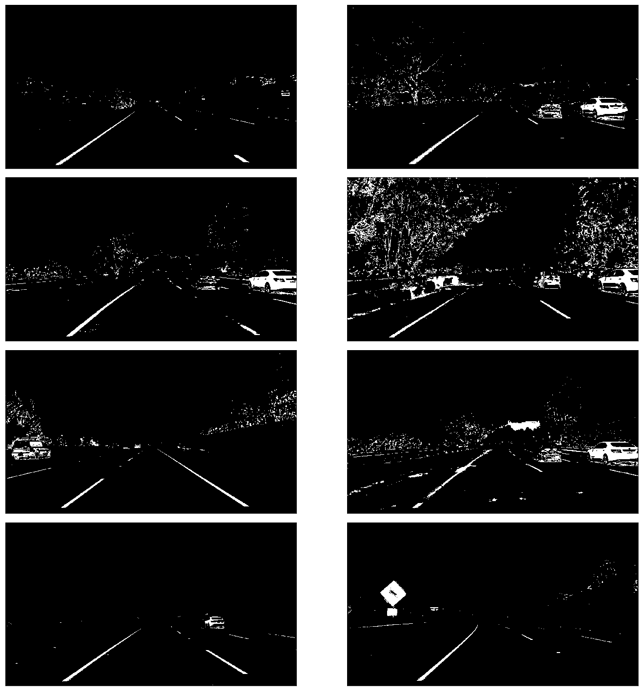
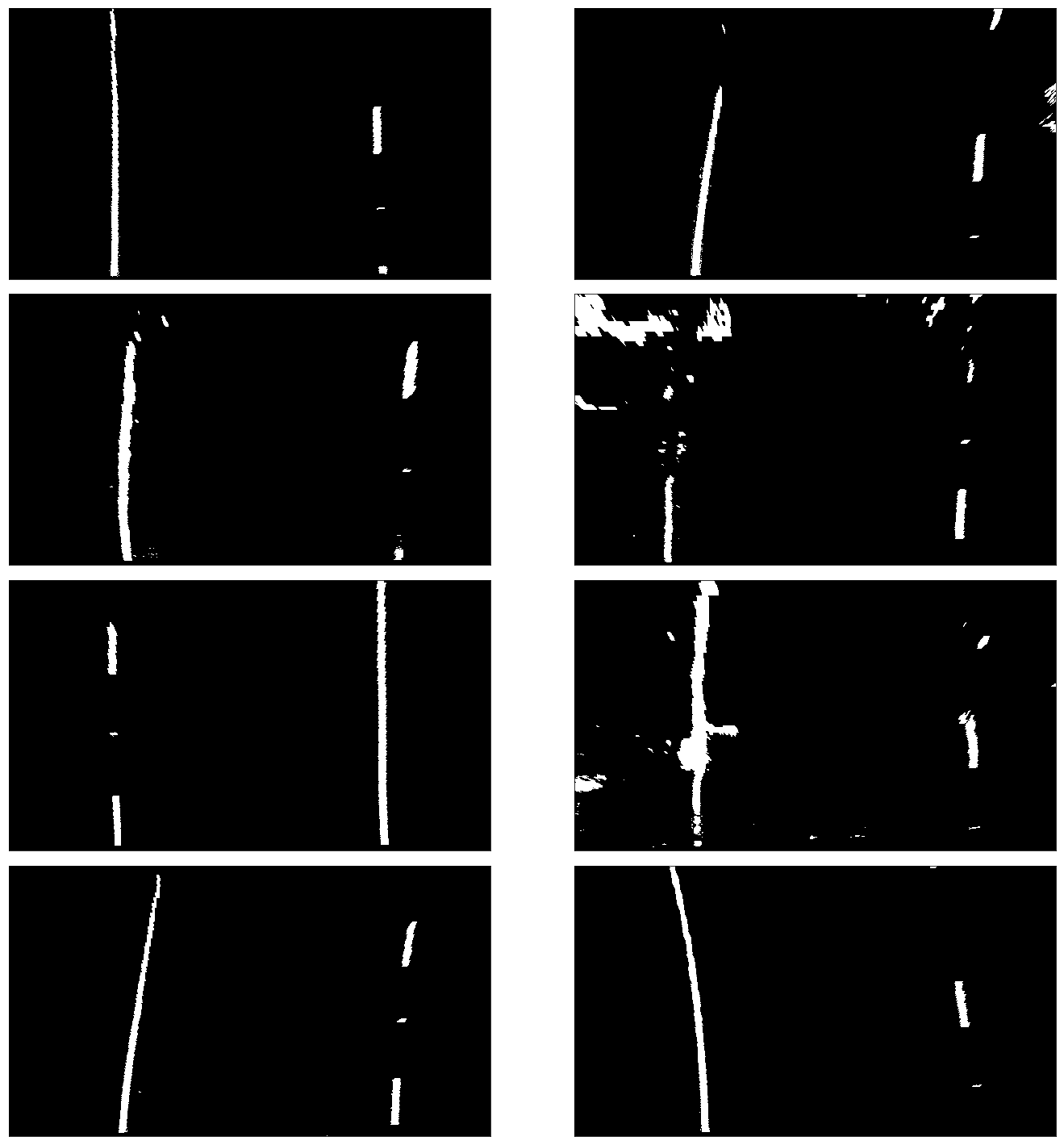
With undistorted images, the pipeline now transform the images using Sobel filters (to capture edges and shapes), red and green channels from the RGB representation (to identify yellow), and lightness and saturation channels from the HLS representation. The particular values were chosen through a trial-and-error process. These functions are defined in utils.threshold. A sample of results is provided below.
To detect lanes, it is more helpful to focus on the road itself. Thus, I applied a perspective transform to focus exclusively on the road for the lane detection step. This was done by manually identifying four source points in the original image and four destination points in the resulting transformation. The transformation's performance was evaluated by visually inspecting how parallel the two road lines are in the resulting transformation. This was implemented in utils.perspective.transform_perspective() (lines 5-30). The results are shown below.
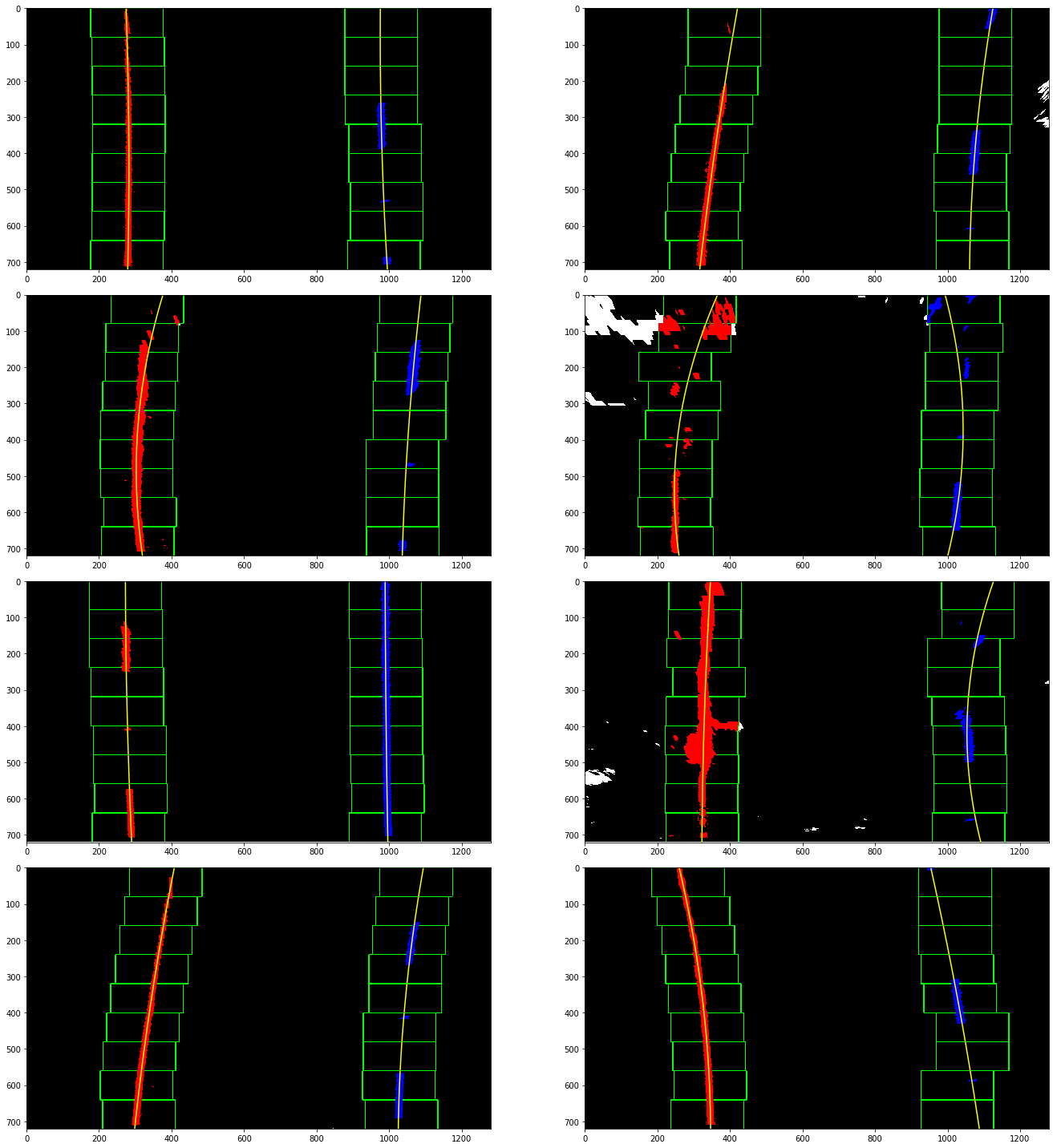
Like other computer vision object detection methods, a sliding window approach is used to search through the entire binary lane image. Within each window, a histogram of the pixel values is generated. As this is a grayscale image, the lanes are white and are thereby identified by local maxima in the histogram. This process continues until the whole image has been viewed. Then, the points that were identified in the sliding window are used to fit a 2nd-order polynomial function that represents the lane lines themselves. This is implemented in utils.detection.hist_lane_detection() (lines 6-102). Results are shown below.
Using a similar 2nd-order polynomial function, but this time with the points measured in meters (and some additional operations), the curvature of the lane can also be measured. Additionally, the vehicle's position (relative to the center of the road) is estimated by comparing the difference between the road's center and the center of the image itself.
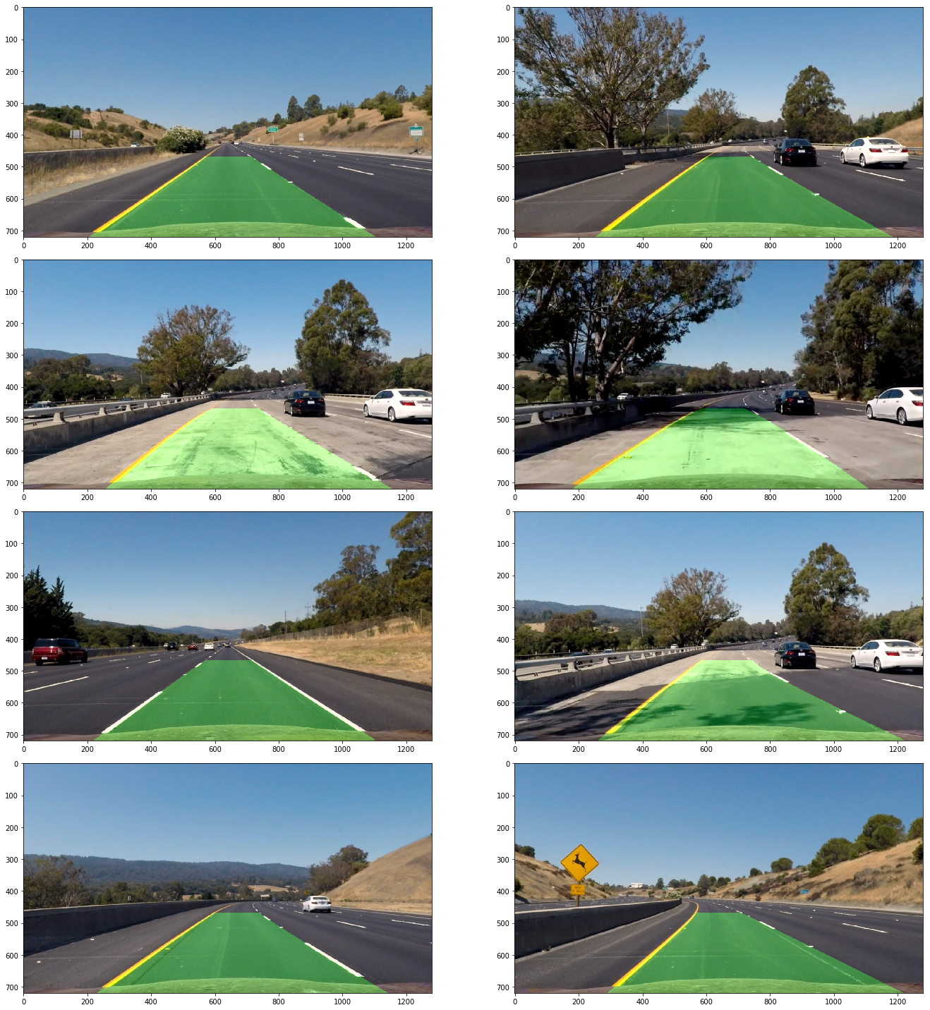
An inverse perspective transform was performed using utils.perspective.inverse_transform_perspective() (lines 33-57). The results are provided below.
A video of the pipeline's output can be found at this link. It flickers under some lighting and color changes, but has an overall acceptable performance.
A major problem with the existing pipeline is that it would not be able to provide the car with lane information on an unmarked road. Furthermore, if a vehicle passed into this "cone of detection", it would directly interfere with the histogram approach.
Given that, and the monotony of trying different filter values, this could be improved by utilizing a machine learning approach. Ideally, a neural network model to automatically capture features.
