Much of this guide is specific to printers running Klipper.
This guide was originally written for the Voron community, however all of the tuning sections should work on any Klipper printer. Some of the bullet points and hardware troubleshooting tips are still Voron specific, however.
(!) Please pay special attention to anything bolded and marked with "(!)"
My SuperSlicer profiles are located here.
If you have issues, comments, or suggestions, please let me know on Discord: Ellis#4980
You can find bed the models and textures I am using in Hartk's GitHub repo. The bed texture I am using is an older one from him in VoronUsers.
Thank you to bythorsthunder for help with testing these methods and providing some of the photos.

- Before We Begin
- Print Tuning
- Printer Tuning
- Miscellaneous
- Troubleshooting
- BMG Clockwork Backlash Issues
- Bulging
- Bulges at STL Vertices
- Bulging Patterns on Overhangs (SS)
- Crimps
- Error: "Command Format Mismatch"
- Extruder Skipping
- First Layer / Squish Consistency Issues
- Layer Shifting
- PLA is Overheating
- Pockmarks
- Repeating Vertical Fine Artifacts (VFAs) With ~2mm Spacing
- Repeating Vertical Fine Artifacts (VFAs) With Non-2mm Spacing
- Slicer is Putting Heating G-codes in the Wrong Place/Order
- Small Infill Areas Look Overextruded
Please remember that tuning prints will get you close, but they are should not be taken as gospel. You should get in the habit of finely adjusting based on actual prints afterwards.
My methods are all purely visual / based on intuition.
I avoid using calipers as much as possible for initial tuning, for a few reasons:
- Not everyone has high quality calipers.
- Not everyone uses them in exactly the same way.
- 3D printing is not completely consistent.
- Wall thicknesses and first layer thicknesses can vary in different places.
- Flow characteristics can change at different speeds.
- Things like bulges, overextruded areas, and layer misalignments can throw measurements off too.
I certainly don't mean to imply that calibrating with calipers is wrong or impossible. Many of these things can be mitigated.
I just wanted to share what I have personally found to result in the best quality prints. It also becomes more accessible by not requiring quality calipers.
Before you follow any tuning methods in this guide, ensure that:
-
Voron V2: I highly recommend following my Voron V2 gantry squaring instructions first.
-
(!) Everything is tight (seriously, check again)
- Go back again and re-tighten every single screw you can possibly find, especially grub screws, linear rails, and everything in the toolhead.
- I do this once every once in a while, and I often find something that has shaken loose and is causing me issues that are extremely difficult to troubleshoot.
-
(!) Your nozzle is not partially clogged.
- If your nozzle is partially clogged, you may not even notice. You may be able to print, but you will have an extremely difficult time trying to tune.
- Ensure that you can easily extrude by hand with the filament latch open.
- Ensure that the material falls straight down out of the nozzle when extruding midair. It should not shoot out to the side.
- Hit it with a nozzle cleaning needle just in case.
- If your nozzle is partially clogged, you may not even notice. You may be able to print, but you will have an extremely difficult time trying to tune.
-
Your thermistors are the correct types in your config. Please double check them.
-
(!) If you use any NTC 100K B3950 thermistors, update Klipper to the most recent version and change all instances of
sensor_type: NTC 100K beta 3950tosensor_type: Generic 3950in your config. There was a bug causing these thermistors to be inaccurate, which was fixed with a recent deprecation.-
Please note that some other features have been deprecated recently too. If you have not updated Klipper in a while, please see here for instructions on how to fix up your config for the new Klipper version.
- You may also need to recompile/reflash your MCUs if you get a "command format mismatch" error after updating. See here.
-
-
-
Your motion components are clean, particularly between gear/pulley/idler teeth.
-
Your nozzle is clean.
-
Your nozzle has been tightened while hot (unless it's a Revo), and is not leaking material through the threads around the nozzle or heatbreak.
Any line widths are expressed as a percentage of nozzle diameter.
This allows the guide to remain agnostic to nozzles.
SuperSlicer natively allows percentages to be entered this way.
However:
- Prusa Slicer bases percentages on layer heights instead.
- Cura does not allow percentages at all.
- Other slicers may or may not support this.
(!) For Cura / Prusa Slicer / possibly others, you MUST use static line widths.
For example, enter 0.48mm instead of 120% if you are using a 0.4mm nozzle.
This is what your prints can look like!

But... wait a minute. The lighting changed. Wait, Ellis' prints look like shit?
(this is directly under a bright LED lamp at a low angle)

"I thought you could help me fix it!"
Well... there's a bit of trickery here. Trickery that everyone seems to partake in, willfully or not.
Whenever people show off their prints, they tend to take the photo in direct lighting. You can make just about any print look like shit in harsh lighting, mine included.
And no, it's not just Vorons / <insert brand/printer here>. Even professional printers that cost many thousands of dollars produce prints that look like this in harsh lighting (in fact, a lot of them are worse.)
In low-angle lighting, even a 0.0005mm imperfection is shown off in full force.
(I'm making that number up, but you get the idea.).
Every component in your printer has tiny imperfections. These imperfections all combine with each other and create very minor inconsistencies in your prints. I use authentic Gates pulleys/idlers (A/B/Z) and Hiwin rails with an Orbiter extruder, and I still have these imperfections.
In fact, the single best thing you can do for this issue is simply have fewer components. A simple i3 bed slinger with high quality components could theoretically achieve slightly better print quality than a CoreXY printer in this regard.
There are some improvements to be made, like fixing extruder backlash issues, resolving repeating patterns that correlate to specific components, using static fan speeds, or using higher quality components - but it will never be perfect. Don't drive yourself crazy chasing the unattainable last few percent of quality.
There are entire Discord channels and Discord servers of commiseration. You can tune and get very good looking prints, but you can't tune the pain away.
Think of it like the below graph. You can infinitely approach perfection, but you will never quite reach it.
Efforts at the beginning have a much higher relative quality increase, but you get diminishing returns the closer you get to perfection. 3D printing just has an unfortunate side effect of showing off those imperfections.

Now that we've got all that out of the way, on to the tuning!
I'm going to call it "squish" to be unambiguous. "Z offset" and "z height" can be conflated with other concepts.
-
(!) This section assumes that you have already done a rough Z offset calibration.
-
(!) This section also assumes that you have a consistent first layer squish, both across the entire build surface and between prints.
- (!) See the First Layer / Squish Consistency Issues section, even if you are not having any issues. There is some important information in there that everyone should know, particularly about thermal drift.
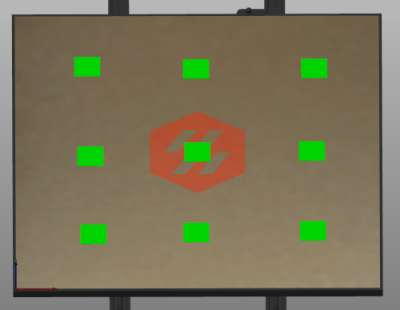
1) Scatter square patches around your bed in your slicer.
- See the Test_Prints folder. Choose a patch that matches your first layer height.

2) Set your first layer height to 0.25 or greater.
- Thinner first layer heights are considerably more sensitive and more difficult to maintain.
3) Set your first layer line width to 120% or greater.
4) Start the print. While it is printing, live adjust z.
- This can be done via g-codes/macros, LCD, or via web. I find it easiest to sit in front of the printer and fine-tune with the LCD.
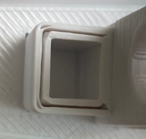
In these examples, the third square is closest.
There are print examples in the next section.
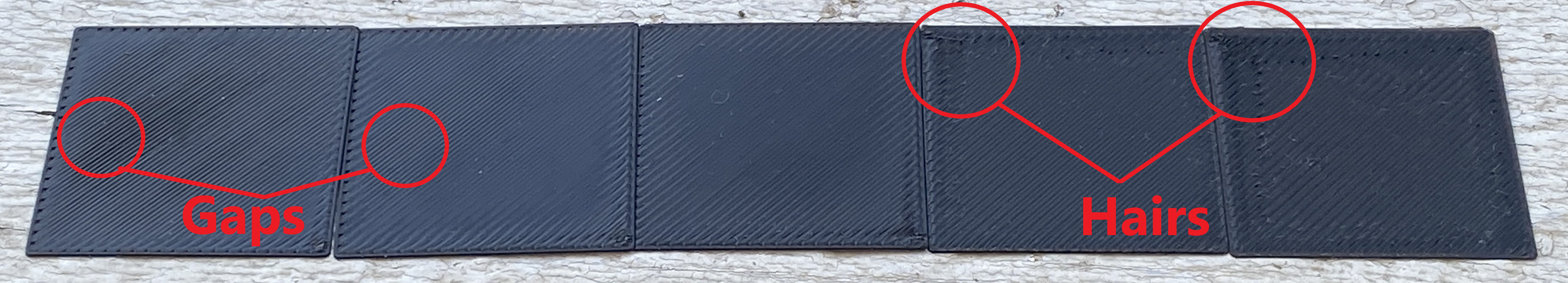
Note: When I refer to "gaps", I mean where you can see BETWEEN/THROUGH the extrusion lines. If you can see any light (excluding pinholes at the perimeter), or the next layer, then you need more squish.
-
- Top Surface
- You don't want too many ridges/hairs on top.
- It's normal to have a little bit of this near the corners, or in small footprint areas.
- You shouldn't see any gaps* between the lines.
- It's fine to have some very small pinholes where the infill meets the perimeters.
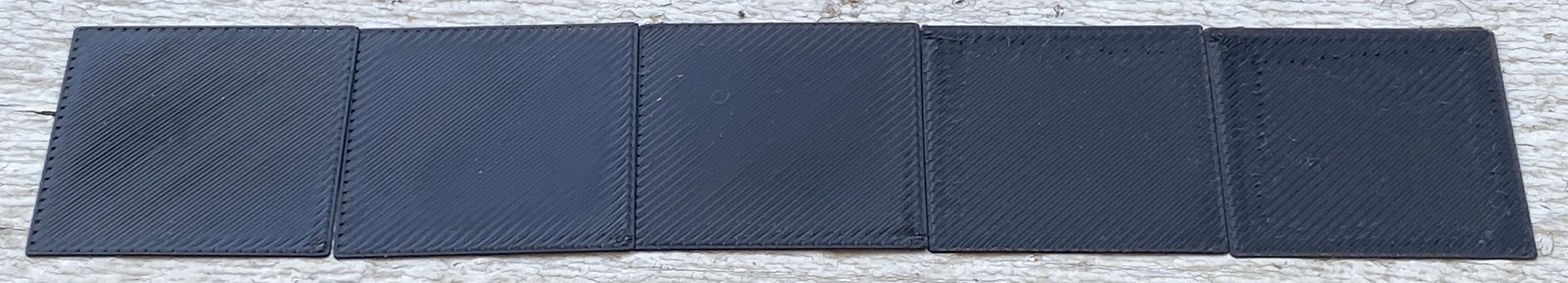
- You don't want too many ridges/hairs on top.
- Bottom Surface
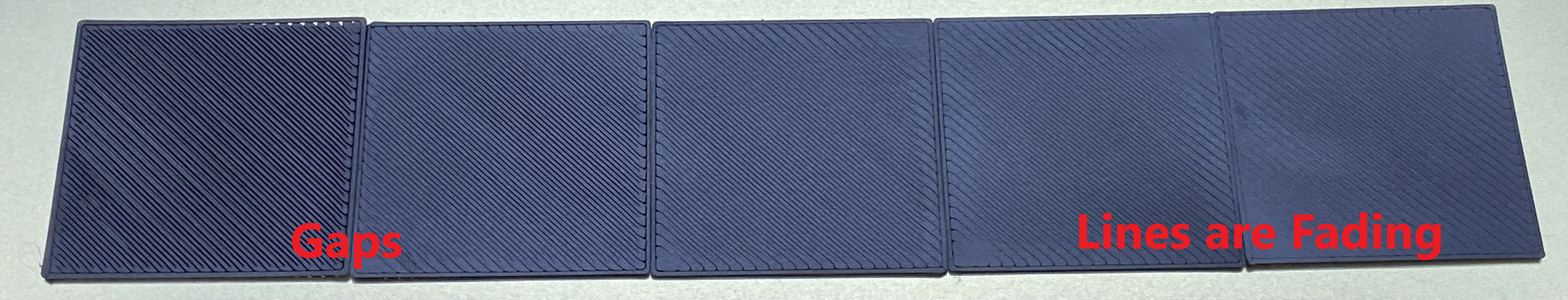
- You should not have any gaps between the lines.
- You should still be able to clearly see the lines. They should not be fading or invisible.
- Top Surface
-
- Top Surface
- Follow the same guidance as for smooth build surfaces (above). You can see hairs/lumps with too much squish, and gaps with not enough squish.
- Bottom Surface
- The lines will not be as visible as on a smooth build surface.
- As with smooth build surfaces, you should not have any gaps between the lines.
- With textured, it's a bit easier to tell squish using the top surface rather than the bottom surface.
- Top Surface


5) Once you are happy with your squish, cancel the print and then save your new offset with one of the below methods:
-
Dedicated Z Endstop:
(With dedicated Z endstops. Stock V0/V2/Trident are set up this way)- Enter
Z_OFFSET_APPLY_ENDSTOP*- This will apply your new offset to your stepper_z's
position_endstop.
- This will apply your new offset to your stepper_z's
- Enter
SAVE_CONFIG.
- Enter
-
Virtual Z Endstop:
(When using the probe as the Z endstop. Stock Switchwire and Legacy are set up this way)- Enter
Z_OFFSET_APPLY_PROBE*- This will apply your new offset to your probe's
z_offset.
- This will apply your new offset to your probe's
- Enter
SAVE_CONFIG.
- Enter
-
Klicky Auto Z Calibration:
(This is a mod, it uses Klicky AND nozzle endstop to automatically baby step before each print. See here for more information.)- Manually adjust your
switch_offsetbased on how much extra you had to baby step.- Higher value = more squish
- Lower value = less squish
- Manually adjust your
* Requires a semi-recent version of Klipper.
You should still clearly be able to see the lines. If it's completely smooth, your squish is too much. If you see gaps between the lines, you need more squish.

-
Can't see any lines, or the lines are starting to fade (smooth PEI):
-
Wavy patterns appear:


-
There are gaps between the lines (you can see through to the next layer):


-
(!) Avoid touching your build surface as much as possible. Oils from your fingers will cause issues. Handle your spring steel with a clean rag or cloth.
-
(!) Ensure that your first layer squish is correct.
-
(!) Thoroughly wash all build plates with dish soap and water, followed by 70+% isopropyl alcohol.
- You should do this even for brand new surfaces.
- Isopropyl alcohol does not do a great job of cleaning oils. It mostly just spreads them around.
- I keep a spray bottle of soapy water next to my printer. Using a paper towel, I scrub with soapy water, then again with isopropyl alcohol (IPA).
- Soap is not needed for every print. You can use IPA most of the time, with occasional soap when it needs further refreshing.
-
Smooth PEI:
- Scuff it up with a Scotch-Brite scouring pad.
- The rough side of a fresh sponge, ~800-1000 grit sandpaper, or other brands of scouring pads could also work.
- This helps immensely, much like how you would scuff/sand a surface before painting or gluing something to it.
- You can refresh the surface this way on occasion, just remember to wash it again afterwards.
- Ensure that you actually have smooth PEI. Some spring steels, particularly the reverse side of some textured steels, are yellow/orange in appearance but do not actually have PEI applied. Inspect the edges of the plate to verify.
- Scuff it up with a Scotch-Brite scouring pad.
-
Textured PEI:
- Needs more squish than smooth PEI, to push the filament into the cracks/dimples.
-
Use thicker first layer line widths.
- I use 120% normally, but higher line widths can further increase adhesion. They push the plastic into the bed with more force, resulting in a better bond.
-
Ensure your PEI is not counterfeit. You may have to ask in the Discord for others' experiences with a given brand. If your PEI is clear rather than yellowish, it's fake.
- Stick to well-known brands.
- This is prevalent with unknown AliExpress and Amazon sellers.
-
Instead of PEI (or to supplement your PEI), you can use adhesives like Vision Miner Nano Polymer.
- Not sponsored: I will praise this stuff until I am blue in the face. It's excellent.
- It grips like crazy.
- Though sometimes it grips too much. It can pull chunks out of glass or pull texture off of beds if too much is used.
- It doesn't leave sticky residue (it does leave some slight whitish coloring though, which can be cleaned)
- It's very thin and easy to spread with a brush.
- It lasts a long time between applications.
- It releases when cooled.
- It grips like crazy.
- Not sponsored: I will praise this stuff until I am blue in the face. It's excellent.
-
As a very last resort, you can try refreshing the surface with acetone. Keep in mind, however that this weakens PEI over time, and I heave heard cases of it destroying certain surfaces (mainly certain brands of textured sheets). Only try this if it's going in the trash otherwise.
Pressure advance changes the distribution of material, not the amount of material.
-
Lower values result in less material in the middle of lines, and more at the ends/corners.
-
Higher values result in more material in the middle of lines, and less at the ends/corners.
-
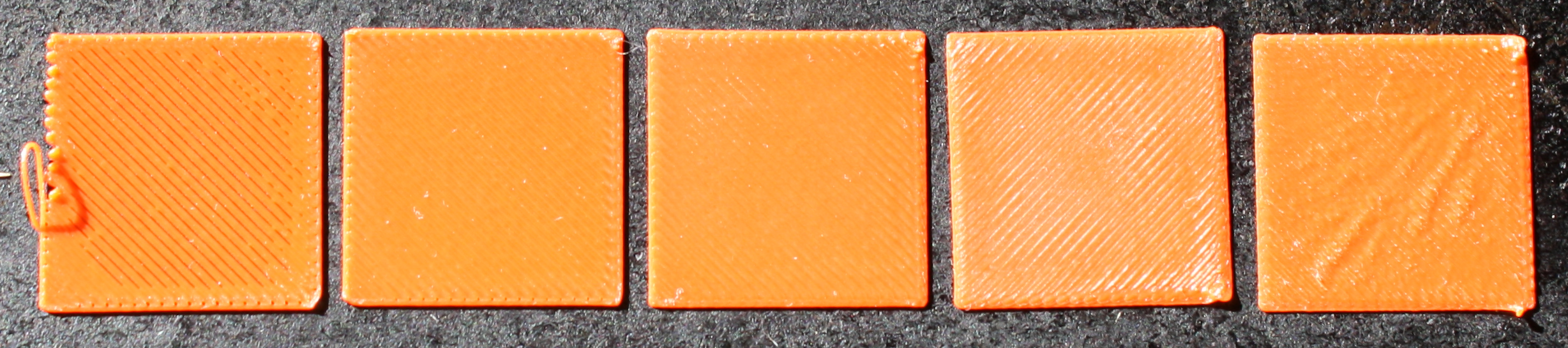
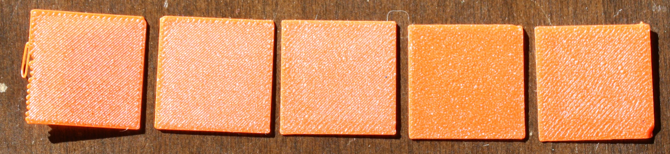
Here is an example:
- PA Values: 0, 0.035, 0.05, 0.09, 0.12 (Galileo clockwork / Dragon HF)
-
Remember: There is rarely such thing as perfect pressure advance. Either accelerations or decelerations will almost always be slightly imperfect. You should always err on the side of lower PA values.
-
Pressure advance can change with different filaments. Typically I only find it necessary to tune per material type - ABS, PETG, PLA, TPU, etc. I will only tune specific brands or colors if they are noticeably different.

There are two approaches - the tower method (simple), and the Lines method (advanced).
(!) You should calibrate your extruder first.
I would highly recommend using the lines method rather than this method, if you can take some time to wrap your head around a small amount of manual g-code editing. It is quicker and more precise. This "tower method" is here for beginners, and works alright, but is not my preferred method.
This is based off of the Klipper Pressure Advance guide, but with some modifications.
The Klipper guide recommends limiting acceleration to 500 and square corner velocity (SCV) to 1, among other things. The intent behind these changes is to exaggerate the effects of pressure advance as much as possible. I'm not a fan of this approach.
In my opinion, it is best to run the calibration in close to normal printing conditions. This can make it slightly harder to tell the difference, but I find it more accurate.
1) Download and slice the pressure advance tower with your normal print settings (accelerations included).
The only modifications you should make are these:
- 120mm/s external perimeter speed
- 1 perimeter
- 0% infill
- 0 top layers
- 0 second "minimum layer time" / "layer time goal" / "slow down if layer print time is below"
- Under filament cooling settings in PS/SS.
- You can use ctrl+f to find settings by name.
- High fan speed
2) Initiate the print.
3) After the print has already started*, enter the following command:
- (Direct Drive)
TUNING_TOWER COMMAND=SET_PRESSURE_ADVANCE PARAMETER=ADVANCE START=0 FACTOR=.0025 - (Bowden)
TUNING_TOWER COMMAND=SET_PRESSURE_ADVANCE PARAMETER=ADVANCE START=0 FACTOR=.025
You should now see increasing pressure advance values reporting to the g-code terminal as the print progresses.
* Certain patterns in your start g-code can cancel the tuning tower.
* It does not matter how quickly you enter the command, as it is based on height.
* Alternatively, you can temporarily add the tuning tower command after your start g-code.
4) Allow the print to run until it starts showing obvious issues/gaps. Then you may cancel.
5) Measure the height of the perfect PA with calipers (see images below)
- Ensure you are not measuring your Z seam corner.
- There should be no signs of underextrusion before or after the corner.
- It can help to shine a bright flashlight between the walls.
- It is normal for there to be a small amount of bulge on the trailing edge. When in doubt, choose the lower value.
- If the height differs between corners, take a rough average.
6) Calculate your new pressure advance value:
- Multiply measured height by your
FACTOR. - Add the
STARTvalue (usually just 0).
8) In the [extruder] section of your config, update pressure_advance to the new value.
9) Issue RESTART command.
You may need to zoom in here, the differences are subtle. There is always some ambiguity.
Excuse the gigantic photos - high resolution is needed here.


This method is quicker to run and more precise than the tower method, but requires some additional setup, including some start g-code.
(!) You should calibrate your extruder first.
(!) If you are not willing to get familar with setting up start g-code, consider using the tower method instead.
- You can damage your printer if you don't set up the start g-code correctly, for example forgetting
QUAD_GANTRY_LEVELorPRINT_START(if used).
1) Visit the pressure advance calibration site.
- Thanks to Deuce#8801 for setting this up! (It's a modified version of Marlin's linear advance site.)
2) Fill out the parameters specific to your setup (printer name, bed size, retraction, etc.)
3) Modify the Start G-code section.
(!) Exercise caution here. As mentioned previously, you can damage your printer if you don't set up the start g-code correctly, for example forgetting QUAD_GANTRY_LEVEL or PRINT_START (if used).
- This is where you will set your temperatures (
M109/M190). - Copy over your slicer's start g-code (from your printer profile) and paste it beneath the
M109/M190.- You can usually replace the default contents beneath the
M109/M190, but there are some default preperatory g-codes (homing, QGL, etc) just in case.PRINT_STARTmacros usually contains all of this, but please double check.- If you are passing variables to
PRINT_START, remember to append them toPRINT_START. Example:PRINT_START HOTEND=240 BED=110- Your variable naming may be different, e.g.
EXTRUDER=Xinstead ofHOTEND=X. - You can then comment out the separate heating g-codes.
- Your variable naming may be different, e.g.
- If you are passing variables to
- If your start g-code has any slicer variables (for example
[first_layer_bed_temperature]), make sure to replace them with appropriate values. - Remove the
M112. This is an emergency stop, and is there as a reading comprehension check / failsafe. This is just to ensure you don't try to use the default start g-code completely unmodified.
- You can usually replace the default contents beneath the
4) Fill out the tuning parameters. Many can be left at defaults, but here are some specific settings that I recommend:
- Printer
- Layer Height: 0.25mm
- Speed
- Slow Printing Speed: Your
square_corner_velocityFrom your printer.cfg. Default is 5. - Fast Printing Speed: 120mm/sec
- Acceleration: Your perimeter acceleration
- Slow Printing Speed: Your
- Pattern
- Starting Value for PA: 0
- Ending Value for PA:
- Direct Drive: 0.1
- Bowden*: 1.5
- PA Stepping::
- Direct Drive: 0.005
- Bowden*: 0.05
- Print Anchor Frame: Checked
- Advanced
- Nozzle Line Ratio: 1.2
- Prime Nozzle: Unchecked
- Dwell Time: 0
* The bowden values I suggest here cover a very wide range of PA values (0-1.5), because each bowden setup can vary widely. Once you nawrrow down a general range to work in, you may want to run the test again with a narrower range of PA values.
5) Generate and download the g-code file.
6) Print it, and inspect the results.
-
Often times, the best acceleration and decelerations values will not be on the same line. In this case, you should pick a midpoint between both.
ALWAYS choose the lower value if you are not entirely sure.-
This is a great visual representation of what I mentioned earlier: that there is rarely a perfect PA value.
-
In the below example, I would choose about 0.055.
(note: mine is likely higher than a normal Afterburner. I am using an Orbiter + Dragon HF.) -
For Bowden: The values I suggested above for bowden cover a very wide range of PA values (0-1.5), because each bowden setup can vary widely. Once you find a general range to work in from the first test, you may want to run the test again with a narrower range of PA values.
-

The above methods are usually good enough on their own. Choosing the right height/line, however, can take some experience. Here are some things to look out for.
-
Divots or underextrusion at corners and line ends.
-
Gaps between perimeters at corners.
-

-
Bulging at corners and line ends.
-
Gaps between straight line perimeters.
-

You can manually tweak pressure advance based on actual prints. Usually increments of 0.005 (with direct drive) are a good starting point.
(!) You should calibrate your extruder first.
- Calibrating your extruder ensures that the extrusion multiplier will be the same across all printers. Extruder calibration simply ensures that 100mm requested = 100mm extruded. Extrusion multiplier is a per-filament setting, depending on the properties of each material.
(!) You should tune pressure advance first.
- These tests try to remove PA as a variable as much as possible, but having a good PA value is still ideal.
This must be done, at a minimum, per filament brand/type. It may vary by color or by roll, depending how consistent your filament brand of choice is. With KVP I am usually able to run the same EM for all colors.
This is a bit of a debated subject. Ask ten people, get ten different opinions. I will try to explain my rationale.
Getting the perfect extrusion multiplier (EM) is crucial for good looking prints.
Again, this is a debated subject. I don't mean to imply that my below method is the "one true way" of calibrating your EM. I am still discovering things myself, and EM can even have different characteristics at different speeds.
-
- Some guides you will find online mention printing a single or two-walled object and measuring the thickness with calipers.
- While this can result in better dimensional accuracy, I find it to result in less attractive parts. This method has always resulted in more layer inconsistencies and rougher top surfaces for me. My personal approach is to tune until everything looks perfect, then to account for dimensions. All of my tuning methods are purely visual / based on intuition where possible.
- This method assumes that you have good calipers, which many people don't. This can simply limit the accessibility and reliability. The measured widths can also vary depending where you measure it and how much pressure you use, so different people may have different experiences.
- If this method works better for you, by all means continue using it.
- Some guides you will find online mention printing a single or two-walled object and measuring the thickness with calipers.
-
- SuperSlicer has a built-in flow calibration tool, however I do not like this either, for a few reasons:
- It is very reliant on first layer squish.
- Because it uses 100% infill, the first layer squish carries through all the way to the top.
- It has ironing turned on by default.
- The objects are too small. It's normal for smaller infill areas to look a bit more overextruded than larger infill areas.
- SuperSlicer has a built-in flow calibration tool, however I do not like this either, for a few reasons:
Get your prints as smooth as a baby's bottom, THEN account for dimensions if needed (in my opinion).
Follow my below method. It is an aesthetics-first approach. This method creates very smooth top surfaces, and additionally can help with layer consistency/stacking.
This also results in prints that are of perfectly acceptable tolerances for Voron parts (and most other projects) with no further compensation.
(!) Voron parts are designed with shrinkage in mind, so it's fine if the dimensions don't perfectly match CAD. Please don't drive yourself crazy with calipers for Voron parts, they are not always intended to match.
- With the Voron test prints, you are good to go as long as:
- The thread tests screw together nicely, and
- Bearings fit nicely without too much force into the Voron cube (F695 on bottom, 625 on top).
- Firstly, adjust your expectations.
- Remember, our 3D printers are hobby-grade, glorified hot glue guns, not CNC. You will not reliably get 0.01mm tolerances everywhere.
- AFTER tuning extrusion multiplier using my below method:
- Try your slicer's shrinkage compensation settings.
- In some slicers, this is just re-named/glorified X/Y part scaling*.
- *Shrinkage occurs much less in the Z axis.
- 100.5%-101% X/Y scaling is about the range you would expect with ABS.
- Find any suitable test object (larger is generally better), and ensure that you are measuring flat edges and not any corner bulging or seams. Use the resulting measurements to determine how much shrinkage compensation you need.
- In some slicers, this is just re-named/glorified X/Y part scaling*.
- Don't mess with your X/Y/A/B
steps_per_mm/rotation_distance, you will just further confuse matters. You are almost always seeing material shrinkage, NOT issues with your axes.- If dimensions are off by large amounts, you may have the wrong pulleys installed on your motors (for example if you're off by 20%, you probably swapped a 16t pulley with a 20t pulley or vice versa).
- Try your slicer's shrinkage compensation settings.
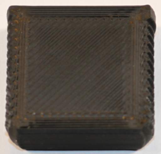
The best method I have found is purely visual/tactile.
We will print some 30x30x3mm cubes. (see the Test_Prints folder)
Print Settings:
- 40+% Infill
We need sparse infill rather than 100% solid infill, to remove the first layer squish from impacting the top layer.
We still need enough to adequately support the top layers. - 100% Top Layer Line Width
In SS: Print settings > width and flow > extrusion width > top infill
This is more subject to interpretation, but I find 100% to have good results. It has a nice finish and tends to show off EM differences the best. - 5 Top Layers
This ensures that we have adequate support for the surface layer. - Monotonic (filled) top infill pattern
Make sure that this is not set to "ironing". If not available, use rectalinear or "lines" instead (depends on slicer). - 30mm/s Solid & Top Solid Infill Speed*
This helps to remove pressure advance as a variable. The faster we go, the more pressure advance will impact our results.
- *If your pressure advance is well tuned, you may actually get more "true to life"/accurate results printing at your normal print speeds. If your pressure advance is off, however, it can throw you off further. - High Fan Speed
As these are only small objects, we need to ensure they have enough cooling so that the top layers don't sag. This depends on your fan, maybe around 80% with AB-BN or 100% with the stock 4020 fan.
Steps:
1) Print multiple test cubes with variations of 2% EM.
- You can do this all in once plate by adjusting settings for each object. Save it as a .3mf file for reuse later.
-
Prusa Slicer:
- There is no way to set the EM per object. You will have to print the test objects one at a time.
-
SuperSlicer:
- (!) Make sure to set your EM to 1 in the filament settings.
The per-object EM settings are a percentage that is multiplied by the EM in your filament settings.
- (!) Make sure to set your EM to 1 in the filament settings.
-
Cura:
-


2) Inspect each cube. Once you are nearing the correct EM, the top should feel noticeably smoother. Too much EM will look and feel rougher, and too little EM will have gaps between the lines.
3) If desired, run the process again but with 0.5% intervals. Most PIF providers tune down to the 0.5% range, some even less.
I have found that most ABS falls within the 91-94% range.
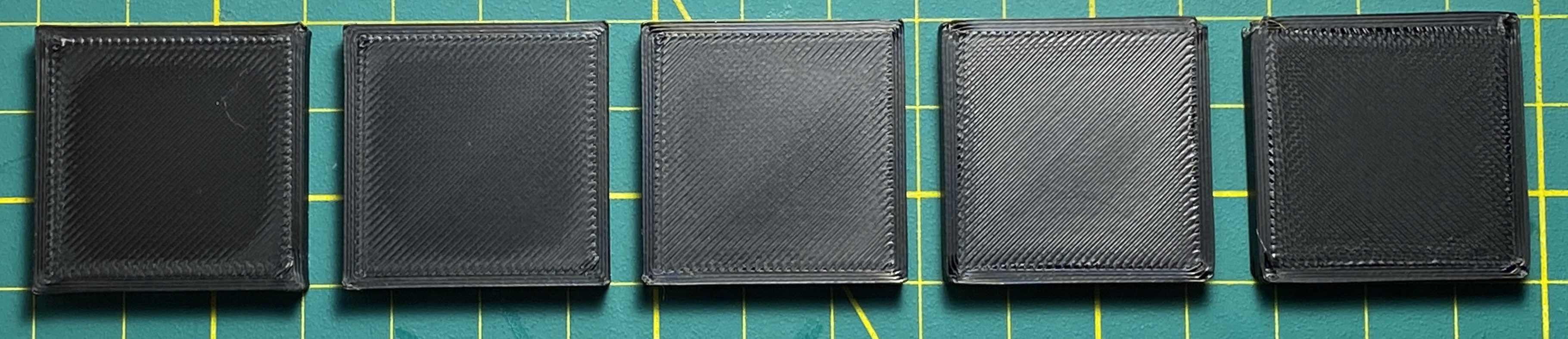
This can be difficult to convey in photos. You may have to zoom in to see the differences. It's easier to see in person - especially because you can manipulate the test prints and look at them in different lighting angles.
Focus all of your attention !!!!! at the center !!!!! of the test prints. It's normal for it to look a bit more overextruded near the edges and corners.
You will get better at this through experience.

Now we run the print again at 0.5% intervals between the "too low" and "too high" examples from above.
Pick the cube that looks best to you. Typically this will be just above where gapping in the center starts to disappear, but not so high that you start to see ridges.
If you can't decide between two cubes, pick the higher one.
Additionally, this is an aesthetics-first approach. If it looks good to you, it's good enough.
In this example, I chose the second cube, as this particular filament started to look nice and shiny with no gapping. Your particular filament may not shine like this.

Remember: pressure advance changes the distribution of material, not the amount of material.
Pressure advance and flow are interrelated, so tuning one can affect the other. The method above has you lowering your top layer speeds in order to reduce the impact of pressure advance as much as possible.
The faster you print, the larger the area that pressure advance will impact. Lower speeds will relegate the effects of pressure advance to be closer to the edges, while higher speeds will cause it to affect a wider area.
Imagine a single extrusion line. In this line, the toolhead accelerates to full speed, stays at top speed, and then decelerates again towards the end of the line. Pressure advance takes effect during these accelerations and decelerations.
In both of the below examples, assume the same acceleration settings.
- When printing with a faster speed, the line is printed in less time, and the extruder spends a larger portion of the line accelerating and decelerating to reach the higher top speed. Therefore, a larger portion of the line is spent equalizing pressure.
- When printing with a slower speed, the line is printed in more time, the extruder spends a smaller portion of the line accelerating and decelerating. Therefore, a smaller portion of the line is spent equalizing pressure, and more of the line is printed at steady speed with steady pressure.
If your actual print results with faster top layers do not look as good as your test cubes, provided they have adequate infill, top layers, etc, your pressure advance value may need further tuning.
You can run faster solid infill, but I would recommend using a moderate top layer speed still. I use 60mm/s.


People often start printing by ABS with no cooling. While this is valid advice for unenclosed printers, it's not a universal rule. ABS often needs some cooling, especially in an enclosure.
There are multiple things you can do to minimize overheating with ABS.
1) Increase fan speeds.
- The higher your chamber temperature is, the more fan speed you will need.
- Use constant fan speeds when possible. For filaments that shrink, varying fan speeds during a print will cause inconsistent layers and banding. Some layers will essentially shrink more than others.
- You probably need higher fan speeds than you think.
- The hotter your enclosure, the higher fan speeds you will need.
- For example I run AB-BN (5015 fan mod) and have a 63C chamber.
- For large plates, I use 40% fan.
- For small plates, I may use up to 80% fan.
- For single small objects, I may use up to 100% fan.
- For example I run AB-BN (5015 fan mod) and have a 63C chamber.
- For very large objects, you may want to be more conservative with cooling. Large objects are much more prone to warping.
- This is the only time I might use differing fan speeds. Lower fan speeds for the majority of the print, with higher fan speeds for overhangs.
- The hotter your enclosure, the higher fan speeds you will need.
- If your prints are curling away from the bed even at low fan speeds, it may actually be a build surface adhesion issue.
2) Increase "minimum layer time" / "layer time goal" / "slow down if layer print time is below"
- Under filament cooling settings in PS/SS.
- You can use ctrl+f to find settings by name.
- I set this to a minimum of 15 seconds.
- This essentially slows down the print for very short/small layers, allowing each layer adequate time to cool.
- When layer times are too short, they do not have enough time to properly cool. You will then be printing on top of layers that are still soft.
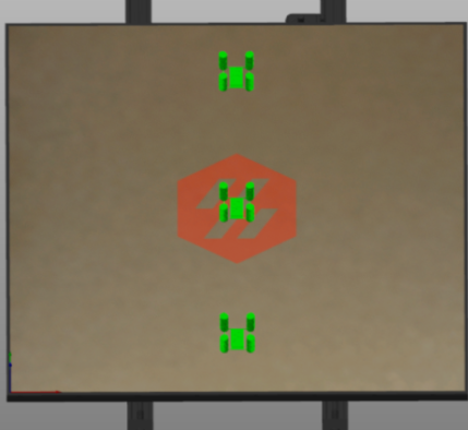
3) Print more objects at once, and spread them out.
- We can allow objects to have some "break time" between layers simply by printing more objects at once. Spread them out to induce more travel time, and maybe even reduce travel speeds.

(!) You should tune pressure advance first. Pressure advance can lower the amount of retraction needed, especially for bowden.
If you typically print with z-hop, leave it on for this test.*
* Don't go overboard or it will cause more stringing. 0.2mm-0.3mm is usually enough.
There is some trial and error involved. You may need to re-run these tests at varying retraction speeds and temperatures if you are not getting good results. You will just have to experiment. You should hot tighten your nozzle (unless it's an E3D Revo).
If you are having persistent issues:
- (!) Ensure that your filament is dry. Wet filament can cause near-unfixable stringing.
- Ensure that your hotend is not leaking around the threads or heat break. This can indicate that your nozzle or heatbreak is loose or not making adequate contact.
- You may need to use less z hop (z lift). I run 0.2mm. Too high gives me stringing.
There are a few factors that can affect your retraction settings, such as:
- Material type
- Print temperature
- Hotend
- Extruder
We will be using using SuperSlicer's calibration tools.
- If you do not typically use SuperSlicer, you can start with one of the built-in Voron profiles for this test.
- The built-in profiles are not great in my opinion, but will work fine just for running the calibration tools.
- Shameless plug: try my profiles later on. There are some other warnings and dependencies, however (please thoroughly read its readme), so just stick with the built-in ones for now.
We will be printing these retraction towers at three different temperatures. If you are confident that your filament temperature is well tuned, you may get good results with just one tower.
1) Ensure that your nozzle is clean. You can use a brass brush while it is heated.
2) Set your fan speed high.
- These are small towers, we don't want them to get melty.
- These are located in the "filament settings" tab, under "cooling".
- Try 80-100%.
3) Set your retract and unretract speeds to 30mm/s to start.
- This is located in the "printer settings" tab, under "extruder 1".
- I have had more luck with slower retraction speeds. Your mileage may vary.
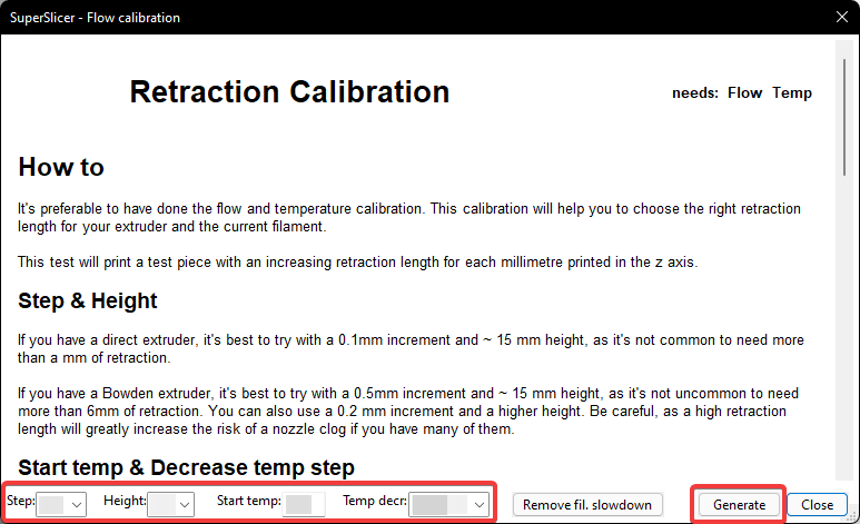
4) Select "extruder retraction calibration" from the menu.

5) Click "remove fil. slowdown".

6) Fill out the parameters and select "Generate".
-
-
Start temp:
- Set a bit higher than your normal printing temps (maybe around 10C higher).
- For this example, I will be using 255C with KVP ABS.
- Set a bit higher than your normal printing temps (maybe around 10C higher).
-
Step:
- Direct drive: 0.1mm
- Bowden: 0.5mm
-
Height:
- Your maximum retraction length will be (height - 1) * step.
- Do not exceed 1mm for direct drive.
(height: 11 when using a step of 0.1mm)- You will rarely need more than this, but it is possible with some high flow hotends and setups. Start with 1mm, only go up to an absolute max of 2mm if required.
- For bowden, this can vary. Try starting with a maximum of 3mm.
(height: 7 when using a step of 0.5mm)- You may need more, depending on a few factors like pressure advance, bowden tube length, bowden tube internal diameter, and how firmly attached the tube is in the couplings.
- Ensure that your bowden tubes are as firmly attached as possible, and do not move too much in and out of their couplings during printing.
- Do not exceed 1mm for direct drive.
- Your maximum retraction length will be (height - 1) * step.
-
Temp decrease (temp decr):
- 3x10°.
- This will print three retraction towers. One will be at your "start temp", the other two will be 10C increments below this.
- 3x10°.
-
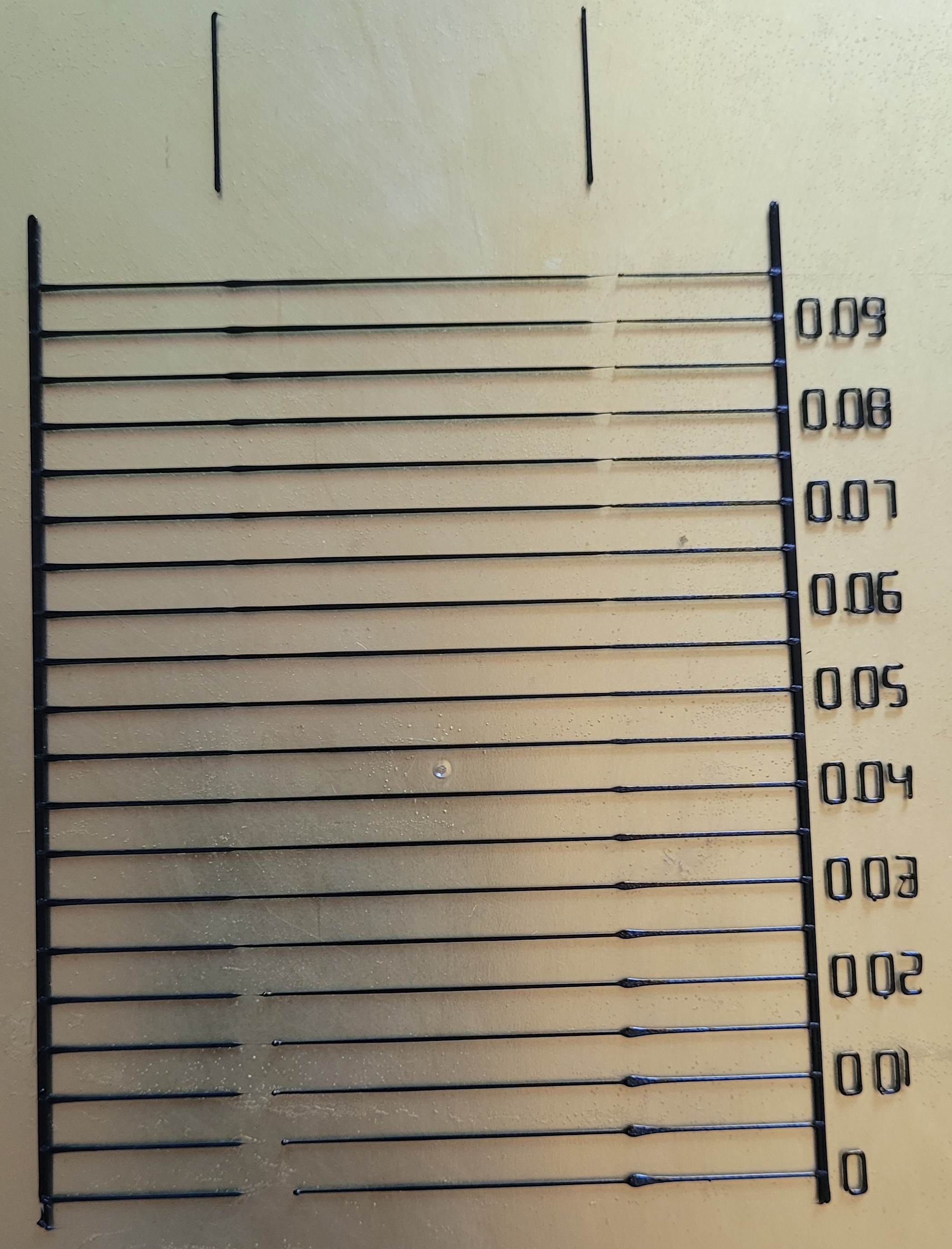
You should get output like this:
-


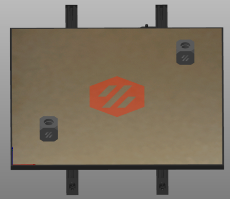
7) (!) Arrange the towers front to back* on your build plate.
-
These objects are printed one at a time. This ensures that they are not knocked over by the gantry/toolhead.
-
Arrange them from the hottest tower at the front, to coolest tower at the back.
- The towers are printed from hottest to coldest. This just lowers the chance of collisions (particularly with poorly written
PRINT_ENDmacros).
- The towers are printed from hottest to coldest. This just lowers the chance of collisions (particularly with poorly written
-
* If you are using a different kinematic system than CoreXY/i3 cartesian, you may need to use a different arrangement. For example, a cross gantry would need diagonal.

8) Print it, and inspect the results.
- If your hotter towers are much stringier, consider choosing a lower extrusion temperature.
- To get your new retraction length:
- Count the rings (from the bottom), subtract 1, and multiply by your "step" value.
- In my opinion, choose a height 1-2 rings higher than where the stringing disappears. This just gives you a bit more headroom for filaments that may behave a bit differently.
- We are subtracting 1 because the first ring is 0 retraction.
- Count the rings (from the bottom), subtract 1, and multiply by your "step" value.
After tuning flow and pressure advance, you may still have some pinholes where your top infill meets your perimeters. This is more prevalent in PS/SS.
This is not necessarily an indicator that your flow or pressure advance are wrong, though they can impact it.
Some people have widely varying overlap settings. You will need to tune this for yourself. I am still figuring out why it varies between people. It may be impacted by line width, but I have not yet tested this theory.
Simply increase "infill/perimeter overlap" (PS/SS) until satisfied.


-
Some use "not connected" for their top infill. This does resolve the pinholes, however I find this to cause the opposite problem. It overshoots.
-
To resolve this overshoot, you then need to lower your overlap. And because overlap is a global setting, this also starts to affect sparse infill/perimeter bonding - and therefore affects print strength.
Volumetric flow rate indicates how much plastic that your hotend/extruder can extrude per second.
Volumetric flow is expressed in mm3/sec (cubic millimeters per second).
You can use this volumetric flow rate to determine how fast your hotend/extruder is able to print.
- See this section to determine what maximum speeds you can print at with a given flow rate.
- See the next section for approximate values for certain hotends.
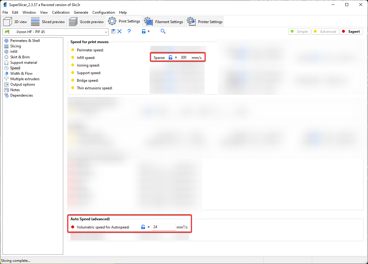
- Some slicers (including Prusa Slicer/SuperSlicer) let you configure this limit to ensure that you never outrun your hotend.
- This means that you can change layer heights, nozzle sizes, line widths, and speeds without worrying about outrunning your hotend.
- You can also set any print speeds to a high "absolute maximum" speed (like infill) and let it be limited by the volumetric flow limit. This essentially prints at the maximum speed your hotend will allow:
- This is utilized by my published SuperSlicer profile (see the "Volumetric Speed / Auto Speed" section for more information.)

| Hotend | Flow Rate (mm3/sec) |
|---|---|
| E3D V6 | 11 |
| E3D Revo | 15 |
| Dragon SF | 15 |
| Dragon HF | 24 |
| Mosquito | 20 |
| Mosquito Magnum | 30 |
You should be okay using an approximate value and just lowering it if you have any issues.
These are approximate values assuming a standard brass 0.4mm nozzle.
Nozzle properties may affect these numbers. For example:
- Larger diameter nozzles will have higher flow rates
- Hardened steel has a lower thermal conductivity and you may get lower flow rates unless you compensate with higher temperatures.
- Plated copper and tungsten carbide have higher thermal conductivity and might allow a bit higher flow rate.
- Bondtech CHT nozzles use a different internal geometry that allows higher flow rates.
If you want to get more scientific, test with a specific nozzle or setup, or your hotend just isn't listed, see here for a testing method.
Working out how quickly you can print at a given volumetric flow rate is quite simple:
- speed = volumetric flow / layer height / line width
Or, inversely,
- volumetric flow = speed * line width * layer height
For example, if your hotend is capable of 24mm3/sec, and you are printing with 0.4mm line width, at 0.2mm layer height:
- 24 / 0.4 / 0.2 = Maximum print speed of 300mm/sec
You will follow a similar process to extruder calibration.
This is a rough calculation. Maximum volumetric flow rate can change with a number of factors, like temperatures, material, and nozzle type.
You should set your limit slightly lower in the slicer for margin of safety, and to avoid having to re-tune for different filaments that don't flow as nicely.
1) Heat your hotend.
2) Extrude a little bit to ensure your E motor is energized and holding.
3) Mark a 120mm length of filament going into your extruder.
4) Extrude at increasing speeds. At each interval, measure to ensure that exactly 100mm entered the extruder.
For example, the gcode to extrude at 5mm/sec is:
M83 ; Relative extrusion mode
G1 E100 F300 ; Extrude 100mm at 5mm/sec
Remember the the F speed is in mm/min, not mm/sec, so multiply your desired speed by 60.
5) Keep increasing speeds and extruding until it starts dropping below 100mm. This is your max flow rate.
6) Convert your extrusion speed to volumetric speed using the below formulas.
7) Enter a slightly lower volumetric speed into the slicer.
mm3 = mm / 0.416
Or, inversely,
mm = mm3 * 0.416
For example, if you extrude at 5mm/sec, that comes out to ~12mm3/sec. (5mm / 0.416)
* For 2.85mm filament, use 0.157 instead of 0.416.
* These fomulas are simplified versions of the cylinder volume equation (V=πr2h) given r and h or V, rounded to 3 significant figures. This is more than enough accuracy for our purposes (down to the thousandths). Calculator
(!) The below guidance is for A/B/X/Y motors only.
Extruder motors/pancake steppers are a bit different, as there is more variance between models.
-
Check with the community first.
- If you are using BoM motors, check the stock configs.
- Check in Discord to see what others are running.
-
You should start off with a more conservative
run_current.- You may be able to attain additional motor performance by increasing currents, but come back to that later. Get your printer working reliably first.
-
Some motors vary.
- I have found my LDO 0.9 degree steppers to be able to achieve notably higher max accels/speeds with higher currents.
- My OMC 1.8 degree motors, on the other hand, performed very well even at moderate currents.
-
We are derating the motors/drivers for margin of safety. Rated currents are the absolute maximum in ideal conditions. In reality, things like chamber and driver temperature come into play. Margin of safety is also standard practice.
-
TMC2209 drivers are rated to 2a RMS, but I would not exceed 1.4a RMS.
Start with around 40-50% of rated current.
For example, with a 2a motor, start around 0.8-1a.
A good rule of thumb is to not exceed 70% of the rated current.
For example, a 2a motor would be about 1.4a max.
- Keep in mind that currents approaching maximum may need greater stepper driver cooling.
- If you are pushing higher currents, you may also want to consider measuring the temperature of your motors. Ensure that they do not exceed 70-75C.
- Measure the temps when actually printing in a heat soaked chamber.
- Some multimeters come with a k-type thermocouple. You can kapton tape it to the motor housing.
- You cannot accurately gauge this by feel.
- The motors themselves can generally handle much more. This temp limit comes from the printed parts rather than the motors themselves.
- Measure the temps when actually printing in a heat soaked chamber.
Recently, Klipper docs have started to recommend against using a separate hold_current. You can achieve this by commenting out hold_current, or by setting it to the same value as your run_current.
If you run a different hold_current, a good rule of thumb is about 70% of your run_current.
This section is purely about finding your absolute maximum speeds/accels. This does not necessarily mean that these speeds or accelerations will be practical to print with - but it can be handy to find the limits of your printer. You can use max speeds for things like travels, mesh, QGL, etc.
You may be able to get higher performance out of your motors by increasing currents (see previous section), but be careful not to push them too high.
You may also get higher maximum accelerations by utilizing input shaper, and may want to re-tune your max accels after tuning input shaper.
1.8° motors can generally reach higher top speeds/accels than 0.9° motors. Higher voltage systems (e.g. 24v vs 12v) can also generally reach higher top speeds/accels.
For example my 2a 0.9° LDO motors top out around 450mm/s. My 2a 1.8° OMC motors topped out closer to 700-800mm/s.
Tune maximum speeds first, THEN tune accelerations separately.
1) Add this macro to your printer.cfg file.
2) If you are already pushing high accels, then lower your max_accel in your config to something closer to "stock" and reload.
- Reference the stock Voron configs for a reasonable starting point.
- Some wild guesses:
- Linear rail CoreXY: 3000mm/s²
- Linear rod CoreXY: 2000mm/s²
- Bed slinger: 1000mm/s²
- Some wild guesses:
max_accelneeds to be high enough to actually reach full speed in a given print volume, but low enough to not risk causing skipping on its own. This is purely to isolate variables. You will come back and tune actual max accels later (step 8).- You can use the "acceleration" graphing calculator at the bottom of the page here to verify that you will be reaching max speed.
- For example, for a 300mm linear rail CoreXY printer:
- Note that the test pattern is inset 20mm by default (to help avoid collisions). Hence the distance of 260mm (300-20*2).
- The blue line shows that a max speed of 500mm/s is actually being reached and maintained.
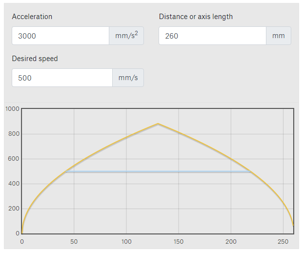
- This graph also shows (the yellow line) that we would max out a bit under 900mm/s at this acceleration/distance.
- For example, for a 300mm linear rail CoreXY printer:

3) Run the TEST_SPEED macro using the instructions below with increasing speeds until you experience skipping.
- Start with a small number of iterations.
- Example:
TEST_SPEED SPEED=350 ITERATIONS=2
- Example:
- Once you experience skipping, back the speed down and try again until you no longer get any skipping.
4) Once you have found a rough maximum, run the test again with a large number of iterations.
- This is essentially an extended torture test.
- Example:
TEST_SPEED SPEED=400 ITERATIONS=50
- Example:
- If you experience any skipping during extended tests, back the speed down again.
5) Use a slightly lower value than your results.
- Sometimes a maximum that works perfectly, even in extended torture tests, can skip during actual prints. Go a bit lower for a margin of safety.
6) Save your new maximum velocity to max_velocity in your config.
7) Return your max_accel in your config to its previous value. (changed in step 2) and then reload.
8) Repeat the process, this time increasing accelerations rather than speeds.
- Example:
TEST_SPEED ACCEL=400 ITERATIONS=2
9) Save your new maximum acceleration to max_accel in your config and reload.
- Set your
max_accel_to_decelto half of this value.
The macro is available here.
This macro will home, QGL (if your printer uses QGL / has not yet done a QGL), move the toolhead in a test pattern at the specificed speeds/accels, and home again.
You will watch, listen, and compare the terminal output from before/after.
SPEED- Speed in mm/sec.- Default: your
max_velocity
- Default: your
ACCEL- Acceleration in mm/sec².- Default: your
max_accel
- Default: your
ITERATIONS- Number of times to repeat the test pattern- Default: 5
BOUND- (Normally you do not need to specify/change this) How far to inset the "large" test pattern from the edges (in mm).This just helps prevent slamming the toolhead into the sides after small skips, and also accounts for imperfectly set printer dimensions.- Default: 20
SMALLPATTERNSIZE- (Normally you do not need to specify/change this) The box size of the "small" movement pattern to perform at the center (in mm).- Default: 20
(!) *Note that any speed or acceleration you input into this macro can exceed
max_velocity and max_accel from your config.
-
TEST_SPEED SPEED=350 ITERATIONS=50 -
TEST_SPEED ACCEL=10000 ITERATIONS=50
1. Watch and listen.
- Often, the skipping will be very obvious. Your toolhead may start shuddering and making erratic movements and loud noises.
- Even if no skipping occurs, your motors might start to make loud resonant noises. This can be an indication that you are near the limit, and should consider backing off a bit.
2. If there was no apparent major skipping, check for minor skipping:
-
Inspect the g-code terminal output:
- Compare the numbers for the X and Y steppers for the first and second homing.
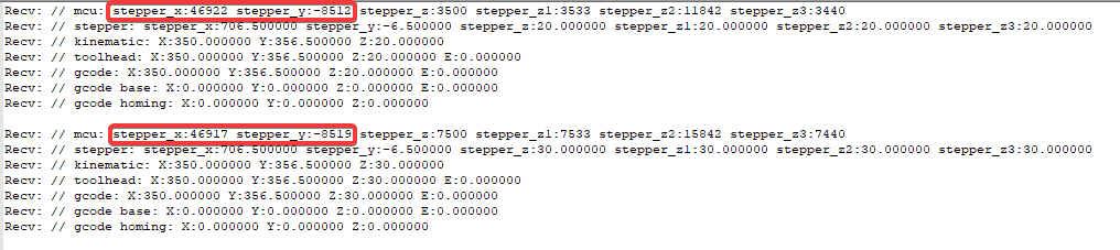
- These numbers represent the microstep position of the toolhead at X/Y max position.
- Ensure that the difference between these numbers has not exceeded a full step.
- For example, I am running
microstepsof 32 for my A and B motors. I would ensure that the values for each axis have not changed by more than 32. - If the number has deviated more than this, that means that the corresponding axis has likely skipped.
- For example, I am running
* Measuring to a full step just accounts for endstop variance. It does not necessarily mean that any microsteps were lost. Endstops are only so accurate.

This section will demonstrate passing temperature variables to PRINT_START.
This method can be used for other slicer variables too, not just temperatures / heating commands.
- The available variables are not always published, however, so you sometimes need to dig around to find the names of them.
- SuperSlicer recently introduced support for custom variables.
By default, slicers will put heating commands either entirely before or after PRINT_START. You have to pass the temps TO PRINT_START in order to control when they happen.
For example I don’t want my nozzle to heat until the very end so it’s not oozing during QGL, mesh etc.
If you don’t use a chamber thermistor, just remove the chamber stuff.
This macro is a template.
You will have to add things like G32,QUAD_GANTRY_LEVEL,BED_MESH_CALIBRATE, or whatever other routines that you need to run during your PRINT_START.
[gcode_macro PRINT_START]
gcode:
    # Parameters
    {% set bedtemp = params.BED|int %}
    {% set hotendtemp = params.HOTEND|int %}
    {% set chambertemp = params.CHAMBER|default(0)|int %}

    G28
    # <insert your routines here>
    M190 S{bedtemp}                                                              ; set & wait for bed temp
    TEMPERATURE_WAIT SENSOR="temperature_sensor chamber" MINIMUM={chambertemp}   ; wait for chamber temp
    # <insert your routines here>
    M109 S{hotendtemp}                                                           ; set & wait for hotend temp
    # <insert your routines here>
    G28 Z                                                                        ; final z homing
This would now be run like PRINT_START BED=110 HOTEND=240 CHAMBER=50.
Chamber defaults to 0 if not specified.
Don't split any of these lines.
(3 lines)
M104 S0 ; Stops PS/SS from sending temp waits separately
M140 S0
PRINT_START BED=[first_layer_bed_temperature] HOTEND={first_layer_temperature[initial_extruder]+extruder_temperature_offset[initial_extruder]} CHAMBER=[chamber_temperature]

(3 lines)
Prusa Slicer doesn’t support chamber temp.
M104 S0 ; Stops PS/SS from sending temp waits separately
M140 S0
PRINT_START BED=[first_layer_bed_temperature] HOTEND={first_layer_temperature[initial_extruder]+extruder_temperature_offset[initial_extruder]}

(1 line)
PRINT_START BED={material_bed_temperature_layer_0} HOTEND={material_print_temperature_layer_0} CHAMBER={build_volume_temperature}

The above section is generally the preferable way to set it up, as it allows you the most control.
If your slicer is putting heating g-codes AFTER PRINT_START and you want them to happen before (or the inverse, or you want to split it), this would be a simpler way to control the ordering. This method only allows you to send temperature g-codes before or after PRINT_START.
To force the g-code ordering, place any of the following g-codes from the following lists in your start gcode where you desire:
M140 S[first_layer_bed_temperature] ; set bed tempM190 S[first_layer_bed_temperature] ; wait for bedM104 S{first_layer_temperature[initial_extruder]+extruder_temperature_offset[initial_extruder]} ; set hotend tempM109 S{first_layer_temperature[initial_extruder]+extruder_temperature_offset[initial_extruder]} ; wait for hotend
M140 S{material_bed_temperature_layer_0} ; set bed tempM190 S{material_bed_temperature_layer_0} ; wait for bedM104 S{material_print_temperature_layer_0} ; set hotend tempM109 S{material_print_temperature_layer_0} ; wait for hotend
- These are just lists of available commands, they don't have to be in this order, nor do you have to use all of them. Place them as you like.
- Each bullet point is only ONE line. Do not split them into multiple lines.
- There are many other variables available in each slicer, and you can pass whatever variables you like to whatever g-codes you like. The available variables are not always documented.
Forces both bed and hotend to heat up fully before executing PRINT_START (SS):

Ensure that you have some backlash between the motor gear and the plastic gear.
- Gauge this with filament loaded and the spring tensioned (the backlash will reduce a bit once it is loaded).
- You want a little backlash, but not too much.
This is adjusted by moving the motor itself up and down.
The motor plate has 3 slotted screw holes to allow for adjustment:

- The top two screws are easily reachable.
- The bottom left screw can be reached by opening the filament latch fully and using a ball-end hex driver.
- Repeating patterns in extrusion
- Accelerated wear and damage of the plastic gear, further contributing to repeating patterns in extrusion.
This can be permanent until replacement. Check the spaces between the gear teeth.
- Repeating patterns in extrusion
- Clacking noises during retraction and pressure advance moves
- Adjusting backlash can help considerably with these issues, but is not always guaranteed to fix it.
- These issues can also be caused by poor quality BMG parts. Genuine Bondtech or Trianglelab BMG parts are best.
- Galileo/Orbiter seem to be less likely to have these extrusion patterns in my experience. Bowden systems are also less prone.
- Test prints: https://mihaidesigns.com/pages/inconsistent-extrusion-test
- Examples:
- See "Setting Expectations"
- The left cube shows an "innie-outie" pattern across each extrusion line.
The right cube is with properly adjusted backlash, and the pattern is lessened. - "Wood Grain":
- Diagonal patterns:
Note: this kind of pattern can also be caused by mechanical issues with printer axes.


I don't have a Mini Afterburner so I can't give an exact process for tweaking it. I believe it also has some slotted screw holes to allow for adjustment.
I have heard that loosening and threadlocking these screws may also help with its extrusion consistency:

This may or may not just be a Prusa Slicer / SuperSlicer thing. I have not tested it in other slicers.


- Disable any "extra perimeters" and "supporting dense layer" settings (PS/SS)
- Reduce perimeter accelerations considerably.


- Your square corner velocity may be too low. (Did you leave it set at 1 by chance?)
- This can also be a sign that your perimeter speeds/accels are too high.


- Some SuperSlicer profiles have "above the bridges" flow set to greater than 100%. This can cause the issues you see above.
- There are three solutions:
- Set "threshold for bridge speed and fan" to 0
- This totally prevents SS from applying bridging settings to overhangs.
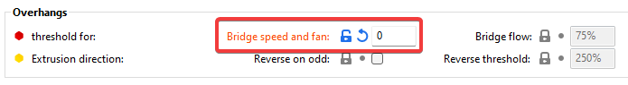
- Set "threshold for bridge flow" to 0
- This prevents SS from applying bridging flow settings to overhangs, but still applies bridging speeds/fan settings.
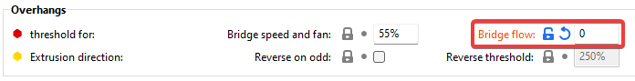
- Reduce "above the bridges" flow to back to 100%
- Set "threshold for bridge speed and fan" to 0
- If these do not fix it, it might instead be an overheating issue.


- Pull on each wire. Ensure that none of the pins are starting to back out of the housings.
- If any pins are backing out, it's possible that you may have crimped incorrectly.
-
You may not have pushed the pins all the way into the housings. Push them in with some sharp tweezers, SIM card tool, or similar until you feel them click into place.
-
Incorrectly crimping microfit pins is very common, and an easy mistake to make.
- Male pins go into the female housings, and vice versa.
- The crimped side of the pins should be facing towards the latch, as shown above.
- The female pins have three sets of arms. You should only crimp the lower two.
- (!) DO NOT CRIMP THESE ARMS.
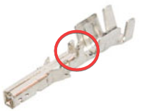
- Example of correct crimps:
- Male pins go into the female housings, and vice versa.
-
Do a "pull test". Ensure that the pins do not come out.
- Microfits hold very strongly. The pins should be nearly impossible to pull out. The wire will usually tear before they ever come out.
-
- If any pins are backing out, it's possible that you may have crimped incorrectly.


Klipper consists of two parts. The "master" host software, and the "slave" MCU firmware.
This error means that you updated Klipper software, but did not update the firmware on your MCUs.
- MCU stands for "microcontroller units". This refers to your printer control board(s) (SKR, Spider, Octopus, etc.)
To fix this, re-compile and re-flash the firmware onto each MCU.
-
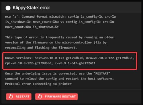
Refer to the example image below. Compare the version numbers in your error message to find out which MCUs need flashing.
-
The "host" version refers to the Klipper software. Each following version number refers to a specific MCU.
-
In this example, the "z" MCU is out of date:
-
-

Refer to the flashing documentation for each specific board*.
-
Check if your board supports SD card updating. It can save you from having to juggle SD cards.
-
Not all boards are supported this way. You may have to manually place firmware.bin on the SD card.
-
I believe this is currently not working for Spider. Manually place firmware.bin on the SD card.
-
-
This includes the Pi MCU if configured (commonly used for accelerometer support).
Generally you should not update Klipper unless there is a specific feature or bug fix that you need.
* Some MCUs are not yet documented on the Voron documentation site. Find the directions from the vendor. Most of them have a github repository with manuals.
These skips will typically be wider than pockmarks.


Skipping below top layer:

-
If it occurs mainly on the first layer, ensure that you are not printing with too much squish or with too much first layer flow.
-
Ensure that your filament gear tension (usually a spring tensioner screw) is not too tight or too loose.
- Yank on the filament and keep tightening the tensioner screw until it stops slipping. Tighten it a little extra, maybe 1-2 turns.
-
Use a reverse bowden tube* with direct drive, and ensure that there is not too much resistance coming from the spool.
- *Reverse bowden tubes go from the direct drive extruder back to the spool (and should be fixed at the spool side), and prevent fast toolhead movements from yanking the filament.
- Use a 3mm inner diameter tube. 1.9mm/2mm ID tubes are more restrictive.
- Ensure that it doesn't have any kinks.
- Ensure that your spool is not catching on anything as it rotates.
- If you are pulling from a dry box, try without.
- For Voron spool holders, make sure you have the PTFE tube piece installed to lessen friction.
- *Reverse bowden tubes go from the direct drive extruder back to the spool (and should be fixed at the spool side), and prevent fast toolhead movements from yanking the filament.
-
For Voron direct drive toolheads, ensure that you have the short piece of PTFE tubing installed between the clockwork and the hotend.
- Make sure it is not too long or too short. You should trim it down until it just fits without compressing the tube.
-
Ensure that there are no issues with your hotend fan.
- Ensure that your hotend fan is running and is not stopping/starting during printing from a wiring issue.
- Also ensure that your hotend fan is running at 100%.
- Some vendor githubs have the
[heater_fan hotend_fan]'smax_powersetting at 0.4 (40%) for some reason. - Ensure that you are running it at the correct voltage.
- Some vendor githubs have the
-
Ensure that your hotend thermistor is correct in your config and that you are not using temps that are too low.
-
(!) If you use any NTC 100K B3950 thermistors, update Klipper to the most recent version and change all instances of
sensor_type: NTC 100K beta 3950tosensor_type: Generic 3950in your config. There was a bug causing these thermistors to be inaccurate, which was fixed with a recent deprecation.-
Please note that some other features have been deprecated recently too. If you have not updated Klipper in a while, please see here for instructions on how to fix up your config for the new Klipper version.
- You may also need to recompile/reflash your MCUs if you get a "command format mismatch" error after updating. See here.
-
-
Ensure that your retraction distance is not too high.
- The default Cura profile uses a high retraction distance, as it is configured for bowden.
- You should generally use a maximum of 1mm for direct drive.
-
With the filament latch open, try extruding by hand. It should be easy.
If there is much resistance, figure out where it is coming from:- You may need to drill out the filament path in the printed parts.
- Your nozzle may be partially clogged.
- See if extruded plastic is shooting out to the side instead of straight down when extruding in mid-air.
- Unclog it using a cold pull or nozzle cleaning needles.
- Try a new nozzle.
- Your heatbreak may be partially clogged.
- Remove the nozzle, cool the hotend, and try pushing fresh filament through it. Make sure to cut off the bulged tip. If there is resistance:
- Unload the filament and remove the nozzle.
- Get access to the top of the hotend (you may need to either remove the hotend or the clockwork).
- Shine a light through the hotend and look into the other side. See if there is any plastic stuck against the walls of the heatbreak or heatsink. If it is obstructed:
- Unplug the hotend fan.
- Heat the hotend up to ~180C.
- We are purposefully inducing heat creep to soften the plastic in the heatbreak.
- Push a long, thin (<=1.8mm) allen key or similar through the top side of the hotend to push the obstruction out of the bottom.
- (!) Turn off the hotend as soon as you have freed the obstruction.
- If you let it cook without cooling for a long time, it will eventually start to soften the printed hotend mounting.
- Be careful - don't burn yourself!
- Remove the nozzle, cool the hotend, and try pushing fresh filament through it. Make sure to cut off the bulged tip. If there is resistance:
-
Ensure that you are using the correct
run_currentfor your motor. Too high or too low can both cause skipping.- As a general rule, don't exceed 50-60% of the rated current of your motor as your
run_current. Some motors like more or less current, though, so your best bet would be to look at the stock configs or to ask in Discord. - Galileo/Orbiter:
- There is some confusion about different motor models.
- If you have the 20mm 1a LDO motor, try 0.65a.
- If you have the 17mm 1a LDO motor, try 0.35-0.4a.
- There is some confusion about different motor models.
- As a general rule, don't exceed 50-60% of the rated current of your motor as your
-
Check your extruder motor crimps and wiring.
-
Check the volumetric speed preview in your slicer. See if it is high for your particular hotend. Or see here to determine your maximum.
- If you are exceeding hotend limits, try lowering your volumetric speed limit in your slicer (PS/SS) or reducing line widths / layer heights / speed (other slicers) until you are under the limit.
-
Try rotating the extruder (if possible) without filament loaded. It should be easy.
-
Try using the AB-BN mod. It optimizes hotend cooling and can help with heat creep issues.
-
Try lowering your extruder motor's microstepping and disabling interpolation (and stealthchop if you have it on, which you shouldn't).
-
Take out the motor, and see how powerful it feels. See if you can stop it easily with your fingers. This may indicate a bad motor or bad wiring.
-
- Try turning the plastic gear with your finger with the motor turned off and filament unloaded. It should be relatively easy. If there is too much resistance:
- Ensure that you have a small amount of backlash in the plastic gear.
- If they are pushed together too hard, it will cause resistance.
- Ensure that your drive shaft is not rubbing against the motor:
- A little cheat I have heard here is to test continuity between the drive shaft and the motor. Test throughout the full rotation.
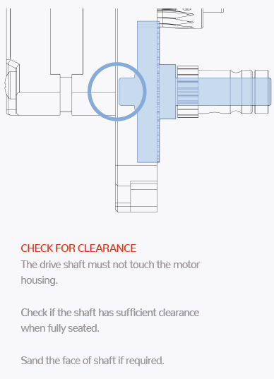
- Ensure that you have a small amount of backlash in the plastic gear.
- Try turning the plastic gear with your finger with the motor turned off and filament unloaded. It should be relatively easy. If there is too much resistance:
(This can affect first layer consistency and z offset consistency between prints.)
-
(!) On larger enclosed printers (i.e. V2 & Trident), ensure that you are heat soaking for at least an hour.
Z will drift upwards as the frame and gantry thermally expand with chamber heat. This can cause your first layer squish to vary between prints, and can even cause your first layer to drift up as it prints.Don't believe me? Look at this. The red line represents Z offset drift over time, as the frame comes up to temperature.

It's not ideal, but just get into a routine - start the heat soak from your phone when you wake up in the morning.
There are ways around this - specifically by using gantry backers in combination with software-based frame thermal expansion compensation, but that is a rabbit hole well outside the scope of this guide.** Some links: 1 2 3 4 5 6 7 8
* This is the one thing I would ask you not to message me about. It is outside the scope of what I am hoping to accomplish with this guide. The graph above is solely intended to demonstrate my point about heat soak times.
(If your squish seems to vary at different spots on the bed)
- In my opinion, you should use bed mesh. I personally recommend generating a bed mesh before every print, by adding
BED_MESH_CALIBRATEto yourPRINT_STARTmacro. (requires the config section in the link above.)-
Do not omit the
relative_reference_indexsetting described in the link above. Follow the formula. -
Use
algorithm: bicubicinstead ofalgorithm: lagrange. -
Some discourage using bed mesh unless absolutely necessary, but I disagree. In my opinion it's cheap insurance. It's very rare for larger printers to have a perfect first layer without it.
-
Your heat soaked mesh will be different from your cold mesh. The bed and gantry can warp with heat. It will even vary at different temperatures. This is why I prefer to generate a fresh bed mesh for every print.
-
Bed mesh can't always save you from mechanical problems.
- Most bed mesh issues are caused by the gantry rather than the bed itself.
- For V2, follow my V2 gantry squaring instructions. A poorly squared gantry can be the root cause of a lot of first layer issues.
- On all CoreXY printers: de-rack.
- For V2, this is part of the gantry squaring instructions above. Please follow those first/instead.
- If you are using dual X rails, make sure they are properly aligned with each other. This can cause left-to-right first layer issues that mesh can't compensate for.
- Ensure that everything is tight in your toolhead and across your X extrusion, including the hotend and nozzle.
- Most bed mesh issues are caused by the gantry rather than the bed itself.
-
Try more mesh points. Usually anything above 5x5 is overkill, but you can try up to 9x9.
- Don't forget to update your
relative_reference_indexwhen changing mesh points.
- Don't forget to update your
-
- For V2:
- Ensure that you place your
BED_MESH_CALIBRATEafter G32, as the stock G32 macro clears bed meshes. - You may need to play with how tight your bed mounting screws are.
- The common advice of only three bed screws, with "one tight, two snug" is generally good advice.
- I've found that if any are too loose, it can cause first layer consistency issues.
- Ensure that your Z belts are properly tensioned. They should all be roughly equal tensions.
- I tension mine to 140hz over a 150mm span of belt.
- Your closed loop belts (the short belts loops in the Z drive units) should be quite tight, but not so tight that they are pulling the motors shaft out of parallel.
- (It's not easily possible to measure these with a frequency)
- Ensure that you place your
- For V0:
- Ensure that your bed is solidly mounted. Check that the screws are not coming loose in the MGN7 carriage.
- For inductive probes:
- Make sure your PEI is not bubbling in places. Inductive probes can only sense the subsurface, so cannot correct for PEI bubbles.
- Try leaving the toolhead sitting close to the center of the bed during your heat soak. Inductive probes thermally drift, and this can pre-heat it so that it does not drift during your mesh generation.
- Microswitch-based magprobes (Klicky/Quickdraw) and other physical probes like BLTouch allow for detection of the actual print surface (though I would recommend Klicky/Quickdraw over BLTouch if you take this route)
- Ensure that there is no debris under your spring steel.
- Disable z lift (z hop) on first layer.
- Check your Z axis. Make sure everything is tight, especially grub screws.
- Run
PROBE_ACCURACYto check for issues with your Z axis repeatability.- My personal comfort zone:
- Standard deviation ≤ 0.004.
- Range ≤ 0.0125.
- On V2, run
PROBE_ACCURACYin each corner of the bed to check all four Z drives.
- My personal comfort zone:
- Ensure that everything is tight in your toolhead and across your X extrusion, including the hotend, nozzle, and probe.
- See the Thermal Drift section. Ensure that you are heat soaking for long enough on larger enclosed printers.
(If your Z offset seems to vary between prints.)
-
Check your Z axis. Make sure everything is tight, especially grub screws.
-
Ensure that everything is tight in your toolhead and across your X extrusion, including the hotend, nozzle, and probe.
-
For nozzle endstops:
- Ensure that your start g-code contains a final z homing with a hot nozzle near the end.
- This ensures that any plastic remaining on the nozzle is squished out of the way, and is less likely to affect your Z offset.
- This also accounts for the small amount of thermal expansion in the nozzle as it heats.
- You can use a nozzle brush mod to automatically clean any debris. You should still home Z with a hot nozzle, though.
- Ensure that the endstop pin is square on top, otherwise it can cause your Z offset to drift as it rotates over time.
- Notching your Z endstop pin (as described in the Voron manuals) can prevent it from rotating.
- Ensure that your nozzle is hitting the center of the pin.
- Ensure that your start g-code contains a final z homing with a hot nozzle near the end.
-
For V2:
- (!) Ensure that you are homing Z again after QGL, as QGL throws off Z height.
- See the above V2 section.
-
For inductive probes as Z endstop (virtual endstop):
- Inductive probes thermally drift, meaning that your Z offset can change at different bed/enclosure temperatures. You may need to calibrate Z offset for the termperatures you intend to print at.
-
For Klicky/Quickdraw Automatic Z Calibration*:
- Ensure that none of your magnets are loose.
- If they are coming loose, make sure to lightly sand the tops of the magnets before gluing them back in. They adhere much better this way.
- Ensure that your
Calibrate_Zmacro is hitting the body of the Klicky switch on the Z endstop, not the button of the Klicky switch. - Try
PROBE_ACCURACYand check how accurate your switch is. Sometimes you may need to try multiple switches to find the "best" one.
- Ensure that none of your magnets are loose.
-
See the Thermal Drift section. Ensure that you are heat soaking for long enough on larger enclosed printers.
* This is a mod. It essentially baby steps for you, to account for different bed heights in addition to nozzle heights.


-
- Check your motor currents. Ensure that the
run_currentconfigured for your A/B/X/Y motors are correct. See this section.
- Check your motor currents. Ensure that the
-
- Check your crimps.
- Ensure that you are using high strand count wire, of 24awg (0.25 mm²) or thicker.
- Low strand count wires / solid core wire will break in the drag chains with repeated bending. These breaks usually will not be visible, as they occur inside of the insulation.
- You should always run your own wire through the drag chains. Don't trust the wire that came with anything.
- Ensure that your wiring is not damaged, shorted, or caught under any screw heads. Check continuity.
-
- Ensure that your stepper drivers sticks are getting adequate cooling.
- Ensure that they have heatsinks installed on them.
- Ensure that they have adequate airflow*.
- * The v0 does not spec stepper driver cooling by default. This is usually fine, as it runs lower motor currents. It may be worth trying, though, if you are having issues (especially if you are running higher motor currents.)
- Ensure that your stepper drivers sticks are getting adequate cooling.
-
Try using z lift (z hop), and check your prints for signs of overheating. Print curling can cause nozzle strikes and subsequent layer shifts.
- Around 0.2-0.3mm of z lift is usually enough. Too much can cause stringing.
-
Ensure that you have good quality motors.
-
Some off-brand motors (notably Oukeda*) have a history of poor quality. You may have to run lower speeds/accels and sometimes higher currents with off-brand motors.
- * Some Oukeda motors have been labeled as "Oukedj". They can't even spell their own brand name correctly.
-
-
Identify which axis the shifting is occuring in by inspecting your prints.
The circles represent a printed object shifting in the direction of the arrows.-
CoreXY:
- When looking at your printer from the front, the B motor is on the left, and A is on the right.
....It goes "BBBAA" like a sheep. Sounds silly, but that's how I remember it. 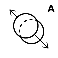
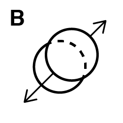
- When looking at your printer from the front, the B motor is on the left, and A is on the right.
-
Cartesian:
-
-
With the motors powered off:
- Move the toolhead by hand in each axis. Feel if one axis has more resistance than the other.
- Also pull on each belt and compare the resistance.
-
Once you have indentified the problem axis, go through and check that entire axis/belt path. Find the source(s) of the mechanical resistance.
-
Make sure your belts are routed correctly.
- Check for belt dust. This can indicate rubbing or misrouting.
- A common mistake is to accidentally route the belts around the plastic post in the back of the A/B drives:
- Ensure that the belts are not rubbing/riding up against any of the bearing flanges.
- It's normal that they may not run perfectly centered. It's usually only an issue if they are rubbing.
-
Loosen the belts, pull the belts over the side of each bearing stack, and ensure that they all spin freely by hand.
-
Try rotating the motors by hand. Sometimes a bad motor will be the cause of the resistance.


Sometimes layer shifting can occur because you are simply asking too much of your steppers. You may be running accelerations or speeds that are too much for your motors to handle.
- Try turning accelerations down, especially if you are not using input shaper.
- Input shaper also allows for higher accelerations, not just less ringing.
- Disable stealthchop.
- Ensure that you are not running your microstepping too high.
- Check this section to test.
- Try running the
TEST_SPEEDmacro without any arguments to test your current maximums.
- Try running the
- You can try increasing motor currents. Don't exceed the maximums described in this section.
- Ensure that you have proper stepper driver cooling before doing this.
- Open the front door at minimum. Or take off all the side panels.
- Use AB-BN or another cooling mod, or:
- Point a fan at it.
- Don't go too crazy, or your bed heater might not be able to keep up.
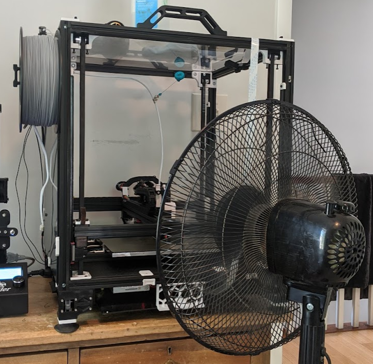
- Don't go too crazy, or your bed heater might not be able to keep up.
- You can also try printing with the bed heater turned off.


- Ensure your Z seam is not set to "random".
- Dry your filament. This can be caused be moisture turning to steam and popping.
- Extrude in midair. Watch and listen. Depending just how wet your filament is, you may hear popping noises and see steam.
- Just because your filament was new/sealed, doesn't mean it's not wet. I've had plenty of filaments come soaking wet even though they were sealed.
- Try a new nozzle.
If the marks are about 2mm apart, that usually means that it's coming from belt/pulley/idler teeth somewhere.
Ensure that these artifacts are still perfectly vertical even when printing irregularly shaped objects like the "rectangular 2 recommended.stl" object here.
If they are not perfectly vertical (i.e. wood grain, diagonal, etc), see this section instead.
Print a square object at 45 degrees and see if it appears A, B, or both. This will tell you which axis/axes to look at.

- Your belts may be too tight. Your A/B belts should be about 110Hz over a 150mm length.
- Don't miss the video link in page linked above.
- Your belts may be rubbing a flange somewhere.
- It's nearly impossible to have them all running dead-center, but you can look around for belt wear and belt dust to find where it may be rubbing too much.
- Ensure your motor pulleys are not positioned too high or too low.
- For V2, follow my V2 gantry squaring instructions. A poorly squared gantry can be the root cause of a lot of first layer issues.
- On all CoreXY printers: de-rack.
- For V2, this is part of the gantry squaring instructions above. Please follow those first/instead.
- Ensure that your pulleys, idlers, and extruder gears/idlers are all clean. Debris can accumulate and compress in the teeth.
- You may have poor quality belts. Only use genuine Gates brand belts.
- You may have poor quality motor pulleys and idlers.
- I, and a few others, have had improvements from switching to authentic Gates brand pulleys and idlers. They are more expensive, but are worth it in my opinion.
- On v2 at least, you only need them for A/B motors and X/Y idlers. Don't waste the money on Z.
- US source:
- For idlers, there is some debate over toothed vs smooth. My personal opinion is:
- Gates toothed idlers > smooth idlers (2x F695 bearings) > china toothed idlers.
- I, and a few others, have had improvements from switching to authentic Gates brand pulleys and idlers. They are more expensive, but are worth it in my opinion.
Try printing the test objects here.
Ensure that the artifacts are always vertical or diagonal, regardless of part geometry. These patterns can be subtle (lumps) or sharp (lines).
If the pattern looks like "wood grain", or any of the example photos in that link, see this section instead.
- Ensure that your A/B pulleys and XY joint idlers are all clean. Debris can accumulate and compress between the teeth.
- You may have a bad/poor quality pulley or toothed idler.
- See above section for more info / links.
- You may have a bad/poor quality bearing.
- Loosen the A/B belts, pull the belt over the side of each bearing flange, and turn each bearing by running it against your finger. Make sure the whole rotation feels smooth.
- You may have poor quality belts. Only use genuine Gates brand belts.
- You may have a bad/poor quality linear rail.
Print two wide square objects, one in normal orientation, and one at 45 degrees.
Inspect the object to see which axes the artifacts appear most prominent in.
(components in each section are in order of likelihood)
- Artifacts are equally prominent in all directions:
- A and B motor pulleys
- X and Y linear rails
- A and B belts
- A and B motors
- Artifacts are most prominent in in A:
- Bearings in A belt path
- A motor pulley
- A belt
- A motor
- Artifacts are most prominent in in B:
- Bearings in B belt path
- B motor pulley
- B belt
- B motor
- Artifacts are most prominent in in X:
- XY joint idlers
- X linear rails(s)
- Artifacts are most prominent in in Y:
- Y linear rails
- Artifacts are most prominent in in A/B/X, but not Y:
- XY joint idlers
- X linear rail(s)
- Artifacts are most prominent in in A/B/Y, but not X:
- Y linear rails
- Artifacts are most prominent in in X/Y, but not A/B:
- A and B motors
- Certain motor models have been found to cause this when both are operating at the same time (i.e. X/Y moves)
- The following motor settings are passed around on the Voron Discord, and apparently can help in some cases (particularly with certain LDO motors on Voron V0). It may also help in other cases, worth a try.
- A and B motors
# Set the below settings for both X AND Y motors, **in addition** to your current settings.

[stepper_x]
microsteps: 32

[tmc2209 stepper_x]
interpolate: false
stealthchop_threshold: 999999  # I'm not sure on this one. I tend to advise against using stealthchop (set to 0). Try both.
driver_TBL: 2
driver_TOFF: 2
driver_HEND: 1
driver_HSTRT: 4
driver_PWM_LIM: 8
driver_PWM_GRAD: 8
driver_PWM_FREQ: 1
driver_PWM_REG: 4
You have two options:
- Pass variables to
PRINT_START(allows the most control, but is more complex)- See the "Passing Variables to PRINT_START" section here.
- Force g-code ordering (only allows changing the g-code order, but is easy to set up)
- See the "Controlling G-code Order Without Passing Variables" section here.

- Some amount of this is unavoidable, but there are some things that may help:
- Use single top perimeters (SuperSlicer). This simply makes these infill areas a bit larger.
- Try reducing your pressure advance smooth time (I use 0.02)
- Try reducing top infill speeds and accelerations.