OpenAmigaVideoHybrid
OpenAmigaVideoHybrid is an Open Hardware implementation of the Video Hybrid integrated circuit used in some Commodore Amiga computers (Commodore Part No. 390229-0x).
Summary
The Video Hybrid, also known as VIDIOT, is a hybrid integrated circuit acting as a Digital-to-Analog Converter (DAC), which converts the digital 4-bit per color video signal of the Amiga into standard (analog) signals suitable to drive a monitor or TV.
It is used in Amiga models A500, A500+, A1000, A2000 and A3000. The Amiga 3000 actually uses two Hybrids: one for the 15kHz video output from Denise and one for the 31kHz video output from Amber. Two Hybrids are also used in the GBA1000 A1000 Clone.
It is also used in some add-on cards, such as the Commodore A2320 Deinterlacer.
The Video Hybrid is a reliable component that usually "just works", but if it gets damaged there is no way of repairing it, the only option is to replace it.
Architecture
The Video Hybrid has 5 sections, one for each of the red, green and blue colors, one for the synchronization signal and one for a composite monochrome signal.
The red, green and blue sections are identical: first, the digital signals are mixed together using the typical binary-weighted resistors DAC configuration. After that, the level of the resulting signal is amplified through an NPN transistor. At the output, the signal is terminated at 75 ohms, as is typical for video signals.
The composite signal is generated in a similar way. The only significant differences are that the weighting resistors have different values and that the amplifier has two stages (NPN + PNP), in order to achieve a higher gain.
The synchronization signal is digital by nature, thus it needs no conversion, only some amplification.
Components
It should now be clear that the Video Hybrid is not much more than a bunch of resistors and transistors, plus a few capacitors.
The original Video Hybrid uses a lot of resistance values which are rather odd by today's standards. While resistors with said values can still be found, they are becoming increasingly rarer and rather expensive.
Besides that, while the basic circuit has always remained the same, Commodore has used different values for some resistors in different revisions of the Video Hybrid. In particular, revision 3 uses higher resistance values in the synchronization signal section. Presumably, this was done to suppress crosstalk among the RGB channels (especially at 31kHz).
What this all means is that newer designs should use different values that are cheap and easy to find, while maintaining functionality and performance.
The tables below lists the component values originally used by Commodore, along with some alternative values readily available in the E24 series, which is common and cheap today. Another column shows the values I actually use.
| Resistors | 390229-01/02 | 390229-03 | E24 | Sukko's | Manufacturer Part Number (MPN) |
|---|---|---|---|---|---|
| R1, R9, R17, R25** | 1k | 1k | 1k | 1k | CRG0805F1K0 |
| R2, R10, R18 | 2k | 2k | 2k | 2k | RMC1/10K202FTP |
| R3*, R11*, R19* | 4k | 4k | 3.9k | 8.2k||8.2k | 4.02k = CRCW08054K02FKEA, 3.9k = CRG0805F3K9 |
| R4*, R12*, R20* | 8k | 8k | 8.2k | 8.2k | 8.06k = CRCW08058K06FKEA, 8.2k = CRG0805F8K2 |
| R5, R13, R21 | 470 | 470 | 470 | 470 | CRG0805F470R |
| R6, R14, R22 | 390 | 390 | 390 | 390 | CRG0805F390R |
| R7, R8, R15, R16, R23, R24, R29**, R39*** | 75 | 75 | 75 | 75 | ERJ6RED75R0V |
| R26** | 220 | 220 | 220 | 220 | CRG0805F220R |
| R27** | 27k | 27k | 27k | 22k | 27k = CRG0805F27K |
| R28** | 150 | 150 | 150 | 220 | 150 = CRG0805F150R |
| R30*** | 18k | 90.9k | 91k | 100k | |
| R31*** | 7.5k | 37.4k | 62k | 68k | 68k = CRG0805F68K |
| R32*** | 2.7k | 13.3k | 22k | 22k | 22k = RMC1/10K223FTP |
| R33*** | 1.2k | 6.04k | 10k | 22k||22k | |
| R34*** | 7.5k | 37.4k | 62k | 68k | |
| R35*** | 3.9k | 19.6k | 20k | 22k | |
| R36*** | 120 | 270 | 220 | 220 | |
| R37***, R38*** | 36 | 36 | 36 | 75||75 | |
| Different Parts Count | 17 | 17 | 16 | 10 |
| Other Components | Value/MPN |
|---|---|
| C1, C2, C3, C4**, C5*** | 100nF |
| Q1, Q2, Q3, Q4**, Q5*** | MMBT3904 |
| Q6*** | MMBT3906 |
Notes:
- To achieve the highest video quality, it is strongly recommended to use resistors with 1% tolerance (or less) everywhere.
- In theory, components marked with a single asterisk* are crucial for a precise and coherent conversion of color data from digital to analog, therefore it should be recommended to stay as close as possible to the original values used by Commodore, encouraging the usage of 4.02k and 8.06k resistors (properly from the E96 series). In practice, my eye can't see any apparent differences when using the indicated values from the E24 series.
- Components marked with two asterisks** are only used by the circuit that amplifies the synchronization signal. Normally, Amigas bring to the video connector only the raw, unamplified signal, making this circuit, and thus these components, totally useless. This is the case, for instance, on A500 Rev.5 boards, where the signal is unrouted. On A500 Rev.8A boards, the amplified and unamplified signals are brought to a jumper pad (JP11), which by default connects the unamplified signal. I'm currently not sure on what other mainboard revisions and other Amiga models do, but there's a good chance that you can get away without mounting these components at all.
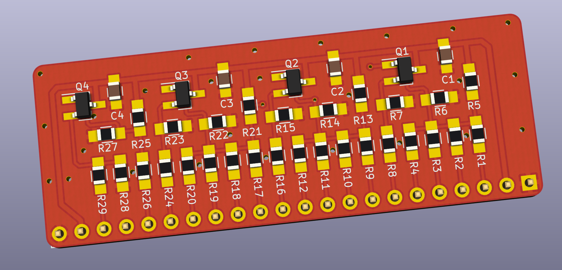
- Components marked with three asterisks*** are only used by the circuit that generates the composite video signal. Since most of the original resistor values are uncommon, and since I don't think anybody really uses the composite output at all, I would just recommend not to mount these parts. If you really care for the (monochrome!) composite output, I wouldn't bother hunting down the correct parts and would just use the approximate values from the E24 series: they might produce a signal that is out-of-standard and that might blow your TV (I take no responsibility, use at your own risk!), but my tests show that they yield a decent image that can still be used for whatever a monochrome output can be useful for. Finally, note that all of these components (and only them!) have been grouped on the back side of the board for quick identification.
- Values listed in the Sukko's column are those that I actually use, in order to cut component costs and the number of different components. The || symbol means "parallel", i.e.: just solder two resistors one over the other. These values work fine with my A500 and my TV and yield results that are satifactory for me, but they might produce a signal that is out-of-standard and that might blow your TV. Again, I take no responsibility, use at your own risk!
- The last column lists the MPN (Manufacturer Part Number) for some reasonably-priced components that I personally tested. With that number, you will be able to buy that exact model of component I used in any shop that's selling electronic components.
Installation
Currently, OpenAmigaVideoHybrid has only been tested on the A500. On this model, you can mount it in vertical as the original Video Hybrid by using 90-degree pin headers, but I recommend a different approach:
- Remove your original Video Hybrid, taking care not to lift any traces.
- Install a row of female machined header pins: these will allow you to install again an original Commodore Video Hybrid, should you want to, and it will fit snugly.
- Solder a row of male machined header pins to your OpenAmigaVideoHybrid: now it will also fit just as snugly and rest just above the output video buffer chips, without touching them and ensuring sufficient heat dissipation.
License
OpenAmigaVideoHybrid is Open Hardware. If you make any modifications to the board, please contribute them back.
Disclaimer
OpenAmigaVideoHybrid is provided to you ‘as is’ and without any express or implied warranties whatsoever with respect to its functionality, operability or use, including, without limitation, any implied warranties of merchantability, fitness for a particular purpose or infringement. We expressly disclaim any liability whatsoever for any direct, indirect, consequential, incidental or special damages, including, without limitation, lost revenues, lost profits, losses resulting from business interruption or loss of data, regardless of the form of action or legal theory under which the liability may be asserted, even if advised of the possibility or likelihood of such damages.
Support the Project
Since the project is open you are free to get the PCBs made by your preferred manufacturer, however in case you want to support the development, you can order them from PCBWay through this link:

You get cheap, professionally-made and good quality PCBs, I get some credit that will help with this and other projects. You won't even have to worry about the various PCB options, it's all pre-configured for you!
Also, if you still have to register to that site, you can use this link to get some bonus initial credit (and yield me some more).
Again, if you want to use another manufacturer, feel free to, don't feel obligated :).
Get Support
If you need help or have questions, you can join the official Telegram group.
Thanks
- The PCB layout was initially inspired by kipper2k's Video Hybrid Replacement.
- This page contains a lot of content translated from amigawiki.
- A good tutorial on DAC architectures helped me to get a better understanding of DACs.
- This helped me understand the rationale behind the actual resistor values available on the market.