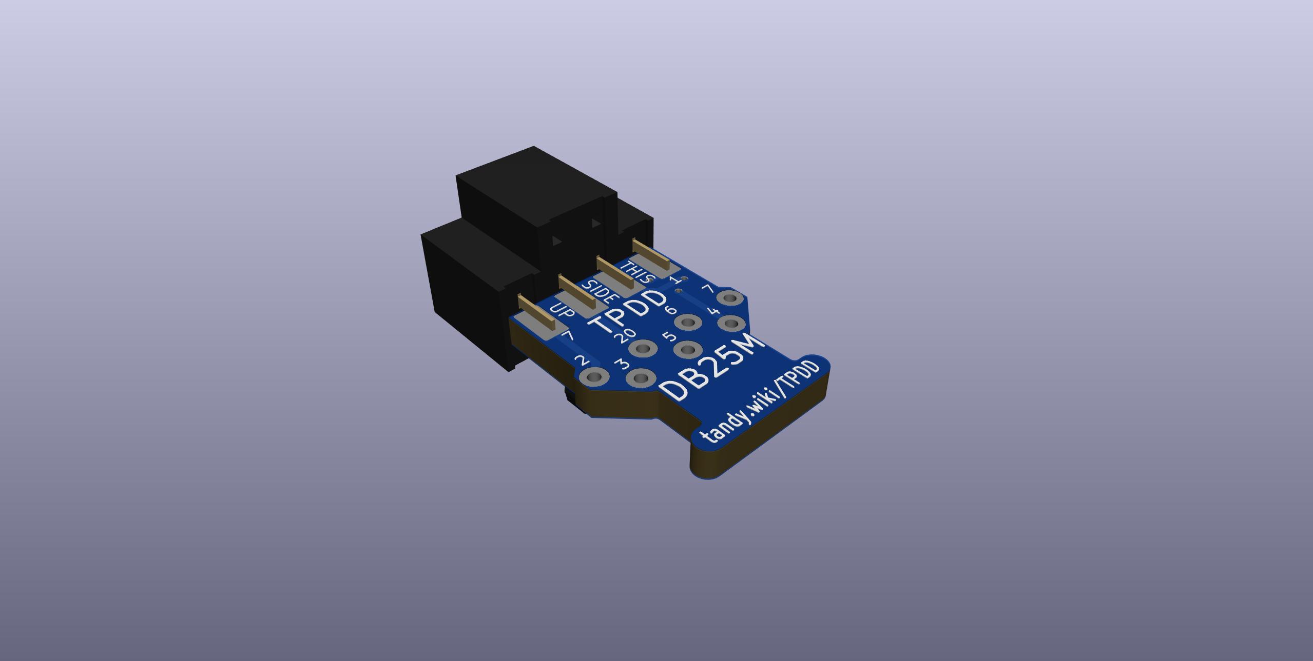
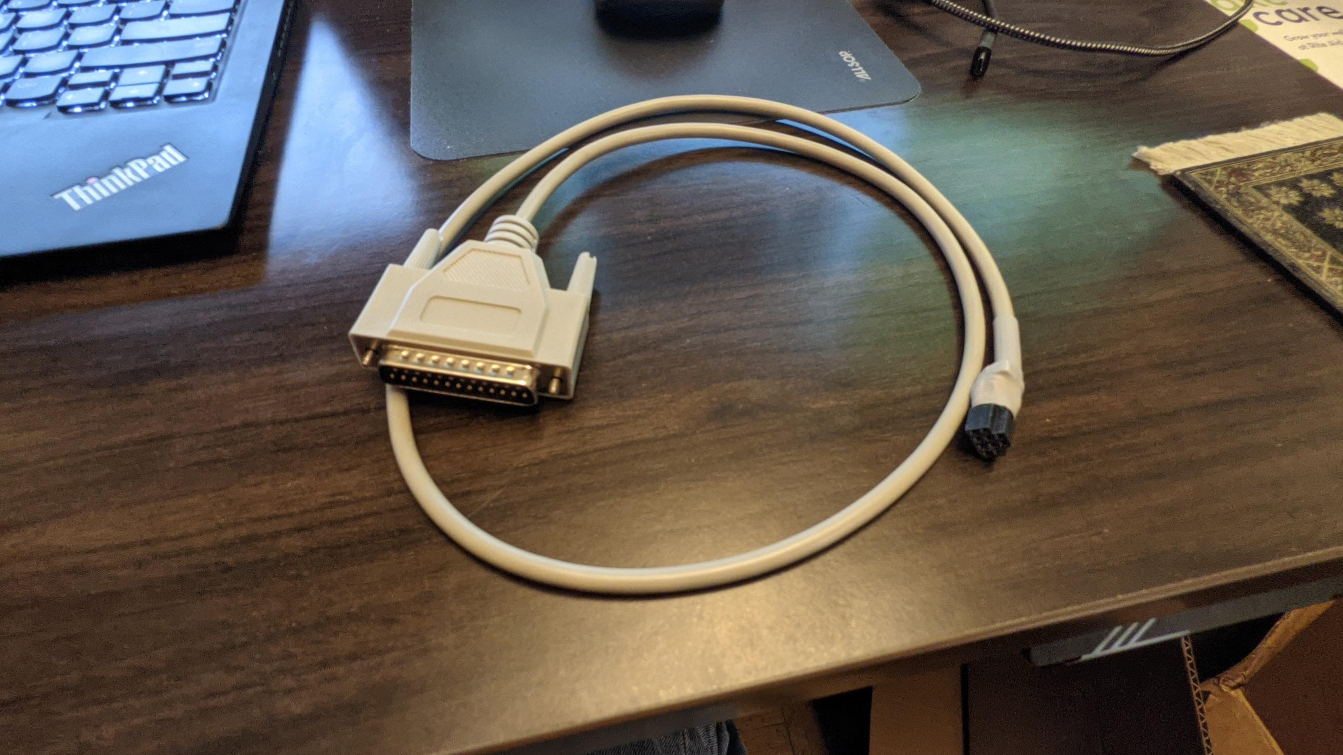
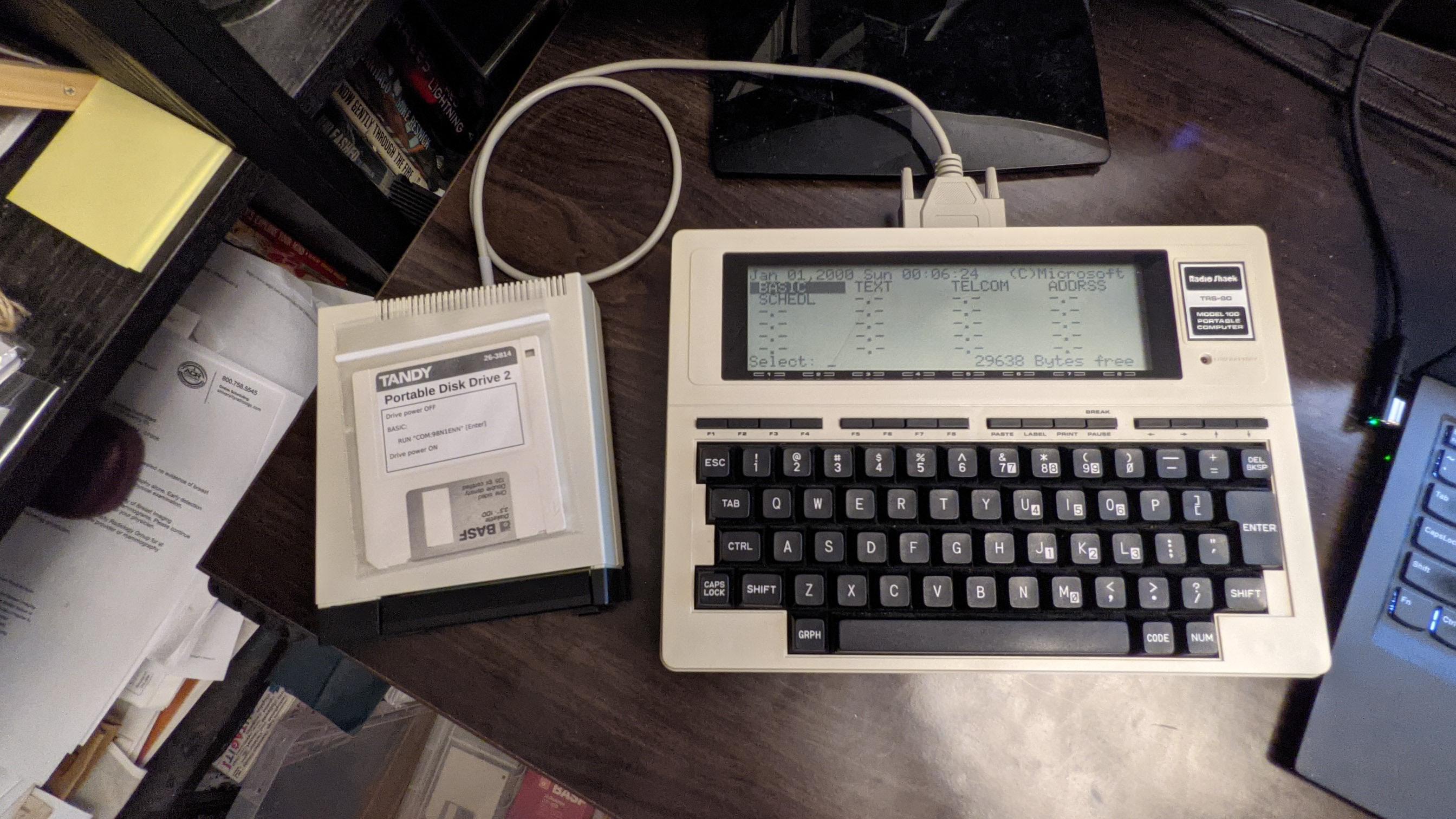
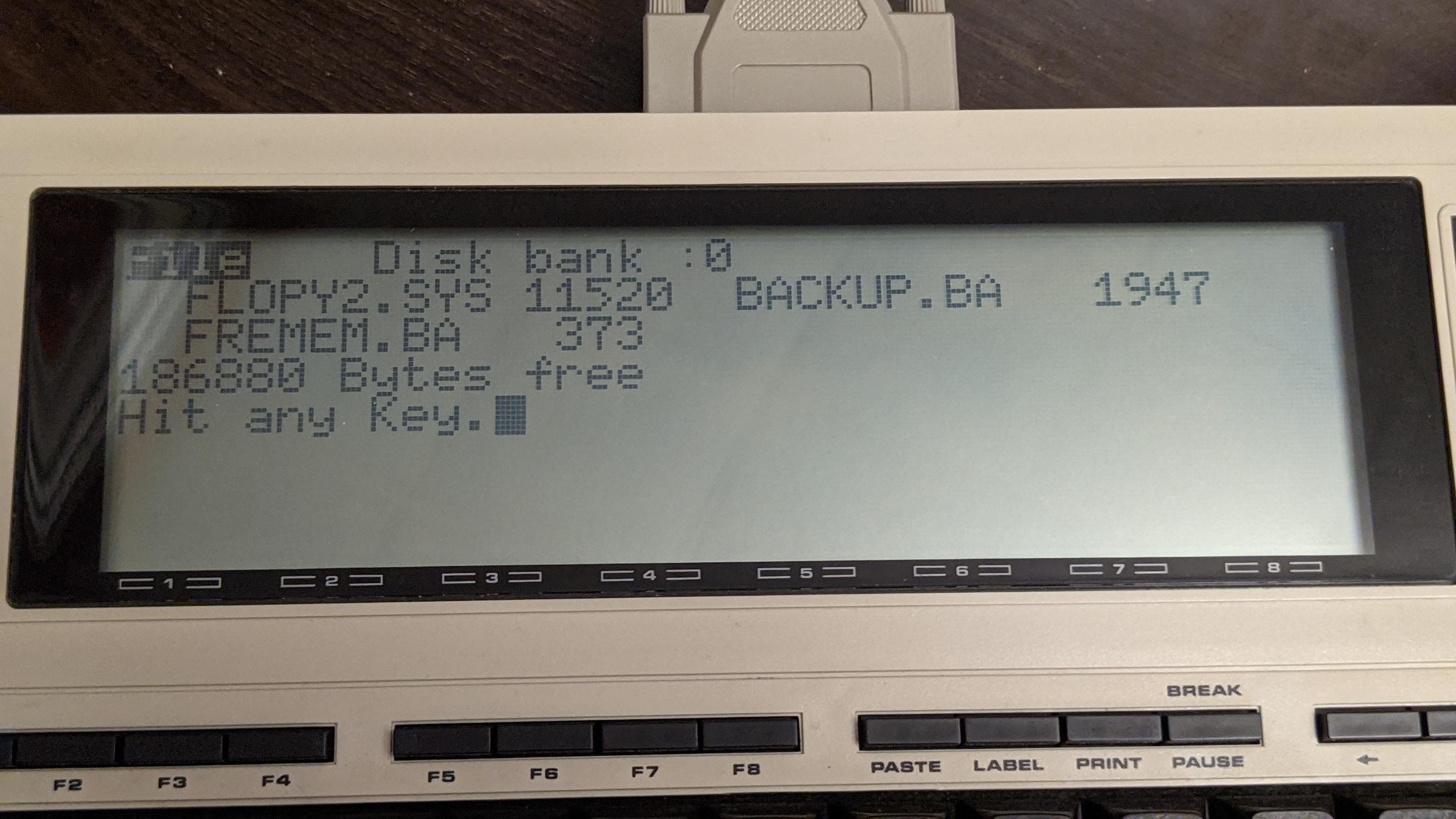
Cable for Tandy Portable Disk Drive
(and TPDD2)
Parts
PCB: OSHPark or PCBWAY
BOM: DigiKey
You will also need:
- 2x4 or longer double-row 2.5mm male pin header (used as an alignment/holder tool while soldering)
- 3/4" length of 1/4" diameter heat-shrink
- 1 1/2" length of 3/8" diameter heat-shrink
- one 0.1" x 4" / 3mm x 100mm zip-tie
- optionally, hot glue
The BOM includes a grey cable. This black cable can be substituted if you want.
Directions
Assembly pictures: https://photos.app.goo.gl/TdYxGhzK94KT9rS78
First, solder the 3 transistors onto the pcb.
Do the center one first, otherwise alignment errors may accumulate and you may not be able to solder the last one.
Next place the pin sockets onto the male pin header in a 1x2-2x3-1x2 arrangement and pull the two un-used pins out of the 2x3 socket.
This is hard to verbalize clearly. Consult the pictiures.
Solder the pcb to the socket pins with the transistors facing DOWN and the polarity bump facing UP.
Again see the pictures.
Cut the the cable either exactly in half to make 2 cables, or just cut off the un-used connector to make one longer cable.
Cut the jacket back to expose about 1.5" of wires.
Use a multimeter continuity tester to identify which color wires go to which pin #s on the DB25M connector.
Consult the table below to determine which wires will not be used.
Cut the un-used wires flush with the outer jacket.
Cover the end of the jacket with a short 3/4" length of 1/4" heat-shrink.
You don't need to insulate each individual wire, just prevent the un-insulated shield ground wire and the ends of the cut-short un-used wires from touching any part of the PCB.
Have the heat-shrink extend only about 1/8" beyond the end of the jacket, just enough to cover the un-used cut wires, no more than that.
Any extra length of heat-shrink will get in the way later.
Shrink the heat-shrink.
Thread a 1 1/2" length of 3/8" heat-shrink onto the cable for later. (Don't shrink it yet)
Strip about 1/8" of insulation from all the remaining wires.
Lastly solder the wires to the pcb following one of the tables below.
Standard Wiring, for a "Model T", like the original cable
The standard version of the cable ends in a male 25-pin plug to connect to the female 25-pin DTE RS-232 port on any of the following machines:
Kyotronic KC-85
TRS-80/TANDY Model 100, 102, 200, 600
NEC PC-8201, PC-8300, PC-8401, PC-8500
Olivetti M10
This is the same arrangement as the original cable that came with the drive.
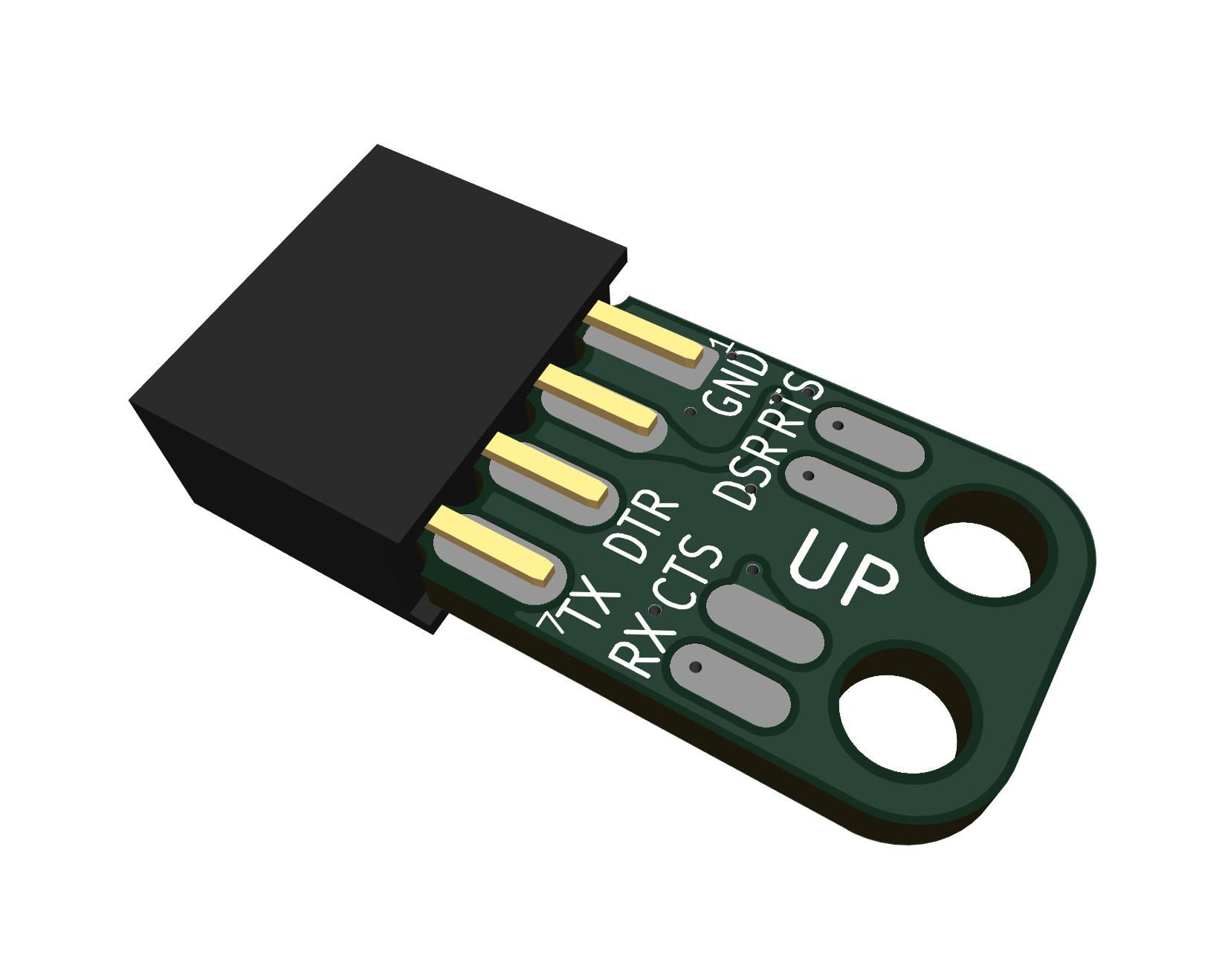
This is the wiring that the silkscreen on the PCB describes, so this table is somewhat redundant. IE, PCB pad #3 goes to DB25M pin #3, PCB pad #20 goes to DB25M pin #20, and so on.
For convenience, the table below also shows the colors for a couple of specific cable options from DigiKey from the BOM links above. If you buy one of the same cables, then your cable should match this table. But don't trust the colors without verifying. If you buy any other cable that isn't specifically exactly the one from one of these BOM links, then ignore the colors and map out your cable yourself.
 |
Signal | PCB pad | GREY CABLE | BLACK CABLE | DB25M pin | Signal | 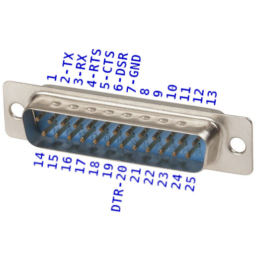 |
|---|---|---|---|---|---|---|---|
| GND | 7 | Green | Yellow | 7 | GND | ||
| RTS | 4 | Purple | Blue | 4 | CTS | ||
| DSR | 6 | Blue | Green | 6 | DTR | ||
| CTS | 5 | Grey | Purple | 5 | RTS | ||
| DTR | 20 | Yellow | Orange | 20 | DSR | ||
| RXD | 3 | Red | Brown | 3 | TXD | ||
| TXD | 2 | Orange | Red | 2 | RXD |
To verify the final result, check the following with a DMM in Continuity and Diode modes.
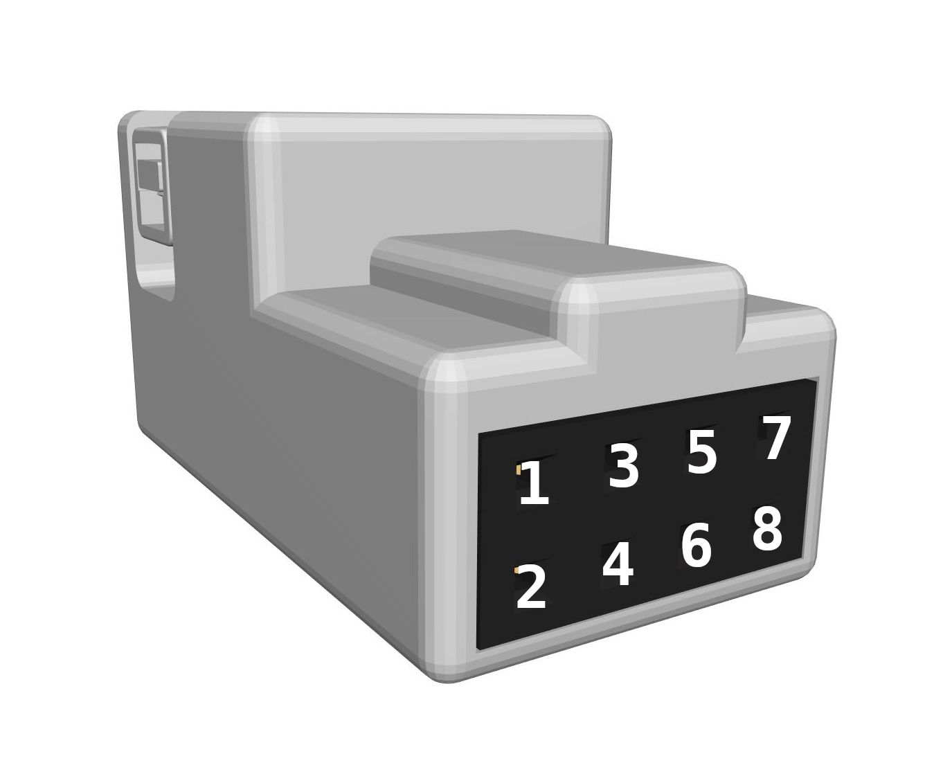 | BLACK | CONT | DIODE | RED |  |
|---|---|---|---|---|---|
| 1 | BEEP | 7 | |||
| 2 | BEEP | 4 | |||
| 3 | 1.7v | 6 | |||
| 4 | 1.7v | 5 | |||
| 5 | BEEP | 20 | |||
| 6 | 1.7v | 3 | |||
| 7 | BEEP | 2 |
Solder the wires on the bottom side of the pcb, with the wire on same side with the transistors, the cut ends on the top side without the transistors.
Flush-cut the top side after soldering, and re-melt each wire end into a smooth dome that won't pierce wire insulation.
Lay the wires down flat on the bottom side of the pcb, pulled away from the connector, and cover the ends of the wires with hot-glue to keep them from flexing at the solder joint.
Hot-glue the end of the cable on the top side of the PCB, and zip-tie the cable to the pcb.
Make sure the zip-tie knot is on the top side of the pcb to the left or right, so that the heat-shrink will be able to get over the bulge. It's a tight fit, but the heat-shrink can be worked over the knot usually.
Slide the heat-shrink over the cable end, up to the back of the connector but not over it. It's a tight fit but the heat-shrink can be worked over the zip-tie knot by just rubbing and pushing repeatedly, and it works a little further along each time. If the bulge is really too big, put a small amount of distilled water or alcohol on the knot and then the heat-shrink can be slid right over. (If you use alcohol, then you may want to heat the whole area for an extra long time when shrinking the heat-shrink, to re-melt the hot-glue, because alcohol seperates hot-glue surface bonds.)
Alternate Wiring
Other machines besides "Model T"'s like the TRS-80 Model 100 can use a TPDD, but their serial ports are different and usually need one or more adapters to work with the 25-pin cable for Model 100/200.
You can make a custom cable that will need no adapters to connect to other kinds of machines by just ignoring the silkscreen on the PCB and use one the following wiring tables instead of the standard wiring table above.
PC / TANDY WP-2 / Atari Portfolio
For Modern PCs and usb-serial adapters, TANDY WP-2, Atari Portfolio, and anything else with a standard DE9M DTE port.
You need a cable with a DE9F on the end instead of DB25M.
The cable in the BOM has both a DB25M on one end and a DE9F on the other end, so you can use the same BOM to make either a "Model T" cable, or a PC cable, or both.
The numbers next to the wire solder pads on the PCB normally indicate the pin# on a DB25M to connect to that pad.
In this case ignore that original meaning and just treat the numbers as arbitrary identifiers. IE, PCB pad #3 is just pad #3, not DB25M pin #3 in this case. Use the table below to find what DE9F pin # each pad should connect to.
 | Signal | PCB pad | DE9F pin | Signal | 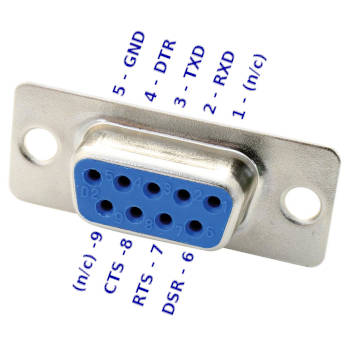 |
|---|---|---|---|---|---|
| GND | 7 | 5 | GND | ||
| RTS | 4 | 8 | CTS | ||
| DSR | 6 | 4 | DTR | ||
| CTS | 5 | 7 | RTS | ||
| DTR | 20 | 6 | DSR | ||
| RXD | 3 | 3 | TXD | ||
| TXD | 2 | 2 | RXD |
To verify the final result, check the following with a DMM in Continuity and Diode modes.
 | BLACK | CONT | DIODE | RED |  |
|---|---|---|---|---|---|
| 1 | BEEP | 5 | |||
| 2 | BEEP | 7 | |||
| 3 | 1.7v | 6 | |||
| 4 | 1.7v | 8 | |||
| 5 | BEEP | 4 | |||
| 6 | 1.7v | 2 | |||
| 7 | BEEP | 3 |
Cambridge Z88
The Cambridge Z88 RS-232 port has a non-standard pinout.
Do not connect this cable to anything but a Cambridge Z88.
You need a different cable than what's in the BOM links above.
Delete the cable in the pre-loaded cart, and add this one instead.
 | Signal | PCB pad | DE9M pin | Signal | 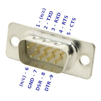 |
|---|---|---|---|---|---|
| GND | 7 | 7 | GND | ||
| RTS | 4 | 5 | CTS | ||
| DSR | 6 | 9 | DTR | ||
| CTS | 5 | 4 | RTS | ||
| DTR | 20 | 8 | DSR | ||
| RXD | 3 | 2 | TXD | ||
| TXD | 2 | 3 | RXD |
Alternate "PITA" pcb
TPDD_Cable_PITA is a version of the cable that uses a PCB that goes into a DB25 backshell instead of a tiny pcb on the TPDD end of the cable, and a "dupont" style connector is used for the TPDD end.
It's called "PITA" because making the dupont end of the cable is a pain in the ass. All in all, the PITA version requires more parts, more tools, and more steps, ... but LESS skill. So if the tiny pcb looks intimidating, or if it's confusing about which wires need to go to which numbers on the tiny pcb, the PITA version is simpler and easier on both counts.
The PITA version BOM.csv specifies a particular model/design of backshell for a reason. The common grey backshell like in Rick Shear's original version below, and almost all other backshell models, actually interferes with the case on the Model 100 and prevents the connector from inserting all the way. Molded cables and this particular backshell don't interfere and they insert all the way.
Credits / History
In the beginning, there was the Marty Goodman Document, and it was good.
More recently, Rick Shear has taken a new and very careful look at a real cable, and the Marty Goodman doc, and has probably identified the "mystery" components that Marty Goodman talks about. It looks right, and the circuit does indeed work.
Rick's initial post
Rick's follow-up
This cable uses the same transistors, but a different physical construction.
