An Arduino project to convert a USB joystick and mouse to digital for use with Commodore or Atari computers.
See the Controllers section below for supported USB devices.
Install the USB Host Shield Library 2.0 version 1.3.2 using the Arduino IDE library manager.
Then compile and upload the program main/main.ino with the Arduino IDE.
Connect a USB joystick, gamepad, mouse, keyboard to the USB Host Shield. If the USB Host Shield (Library) supports the device it will produce events on the Commodore control port. You can also use a USB hub to connect multiple devices.
The following buttons of a gamepad are assigned to the following directions:
| NES | Sony | Control Port |
|---|---|---|
| B | cross | fire |
| A | circle | auto fire A, 10 Hz |
| Y | square | auto fire Y, 5 Hz |
| X | triangle | up |
| n/a | L1 | left |
| n/a | R1 | right |
| L | L2 | left |
| R | R2 | right |
| select | select | fire 2 on POT Y |
| start | start | fire 3 on POT X |
You can configure the frequency of the auto fire from 1 Hz to 255 Hz. To configure the frequency press:
- select+start+A+up : increase the frequency of auto fire A
- select+start+A+down : decrease the frequency of auto fire A
- select+start+Y+up : increase the frequency of auto fire Y
- select+start+Y+down : decrease the frequency of auto fire Y
You can switch the directions of all buttons (lefty mode), press: select+start+B+left.
You can switch the Control Port a device uses by pressing: select+start+L2+up
A USB mouse will be used to output the Commodore 1351 mouse protocol on the Pot X and Pot Y control port inputs. The following table shows the mouse button mapping:
| Mouse | Control Port |
|---|---|
| left | fire |
| middle | down |
| right | up |
| wheel up | left |
| wheel down | right |
| left side | left |
| right side | right |
The mouse wheel is using the Micromys protocol. Left and Right side buttons are used on the Microsoft Intellimouse.
The table below shows how keyboard keys are mapped to the control port:
| Key | Control Port |
|---|---|
| up, num 8, w, i | up |
| down, num 2, s, k | down |
| left, 4, a, j | left |
| right, 6, d, l | right |
| ins, space, ~, enter, F1, b | fire (gamepad B) |
| y | auto fire (gamepad Y) |
| x | up (gamepad X) |
| F2 | fire 2 on POT Y (gamepad select) |
| F3 | fire 3 on POT X (gamepad start) |
This project was tested with a Arduino Uno R3 board and the Arduino USB Host Shield. While the USB Host Shield is no longer sold by the Arduino company, you can easily find clones of the board on AliExpress, where you can also buy a clone Arduino Uno board. To connect the resistors and cables (or Sub-D connectors) you can also purchase a Proto Shield R3.
The following picture shows the location of all I/O pins on the Arduino Uno R3 board.

The following table shows how the 2 control ports with [https://en.wikipedia.org/wiki/D-subminiature](D-sub 9) connectors should be connected to the Arduino pins. This suggested connection is for a Commodore 64. You can change the pin assignments in the config.h file. Except for the +5V (which doesn't need to to connected) and the GND, all connections between the Arduino and the control port should be made via a resistor. The exact resistor value is not important, anything in the 100-500 Ohm range should be fine.
Control Port 1
| Arduino | Resistor | D-sub | Function |
|---|---|---|---|
| A0 | 220 Ohm | 1 | Up |
| A1 | 220 Ohm | 2 | Down |
| A2 | 220 Ohm | 3 | Left |
| A3 | 220 Ohm | 4 | Right |
| A5 | 220 Ohm | 5 | Pot Y |
| A4 | 220 Ohm | 6 | Fire |
| (n/c) | - | 7 | +5V |
| GND | - | 8 | GND |
| D2 | 220 Ohm | 9 | Pot X |
Control Port 2
| Arduino | Resistor | D-sub | Function |
|---|---|---|---|
| D4 | 220 Ohm | 1 | Up |
| D5 | 220 Ohm | 2 | Down |
| D6 | 220 Ohm | 3 | Left |
| D7 | 220 Ohm | 4 | Right |
| D1 | 220 Ohm | 5 | Pot Y |
| D8 | 220 Ohm | 6 | Fire |
| (n/c) | - | 7 | +5V |
| GND | - | 8 | GND |
| D3 | 220 Ohm | 9 | Pot X |
Note: On the Arduino pins D0 and D1 are used for the serial debug console. If you connect the control port Pot Y line to D1, you can't use the serial console any more.
If you want to change the Arduino pin assignments, change the config.h file.
If you have a clone USB Host Shield from China it is likely that the 3.3V and 5V power supply to the board and USB device connector are not connected. The solder pads show a gap. Closing them with a soldering iron should make the USB Host Shield operational. See https://esp8266-notes.blogspot.com/2017/08/defective-arduino-usb-host-shield-boards.html for details.
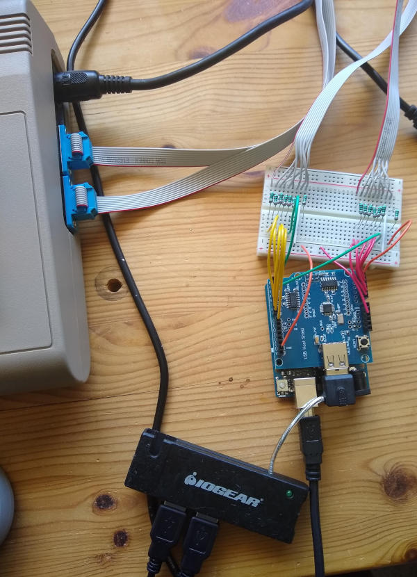
The following picture shows the development prototype with an Arduino Uno, the USB Host Shield, a 4 port USB hub and connections to both Commodore 64 control ports.
the arduino-shield/ directory contains a KiCad project of an Arduino Uno Shield.
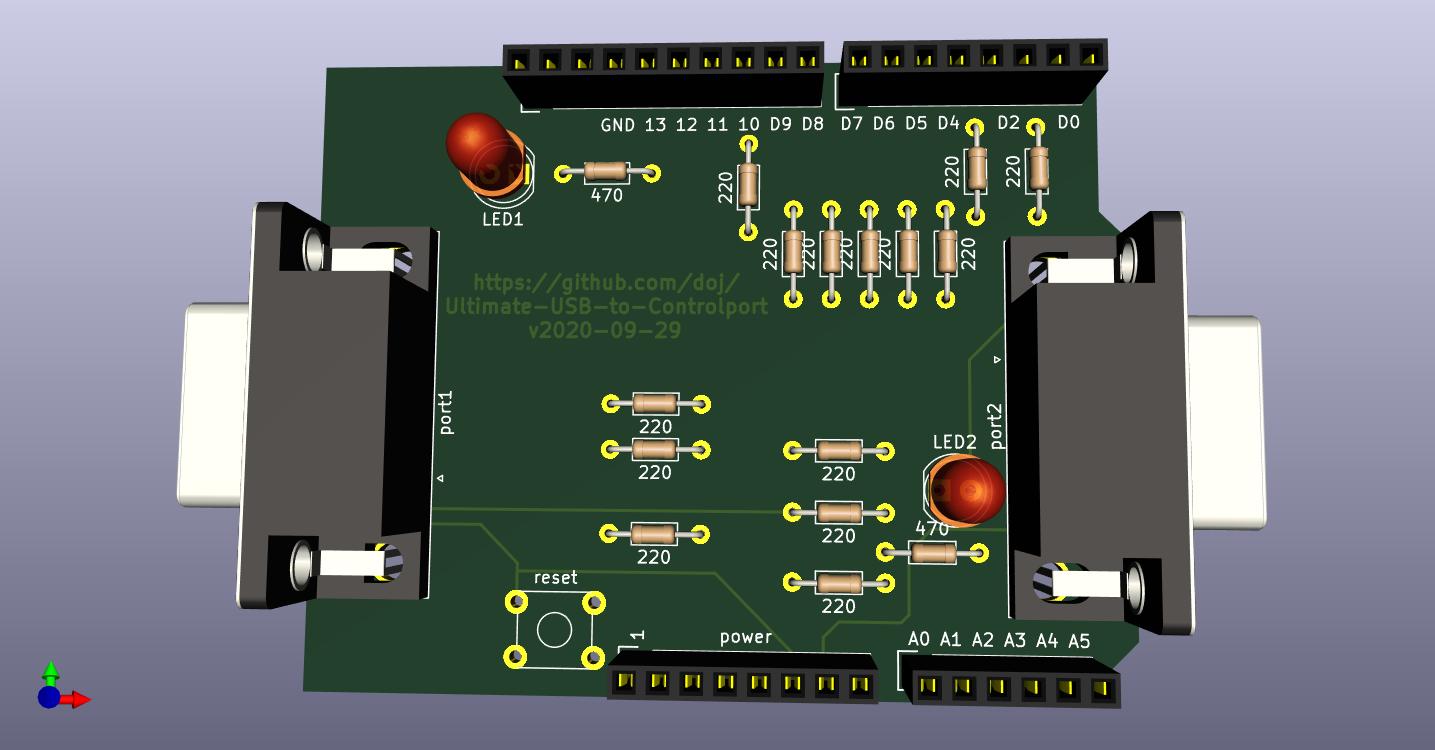
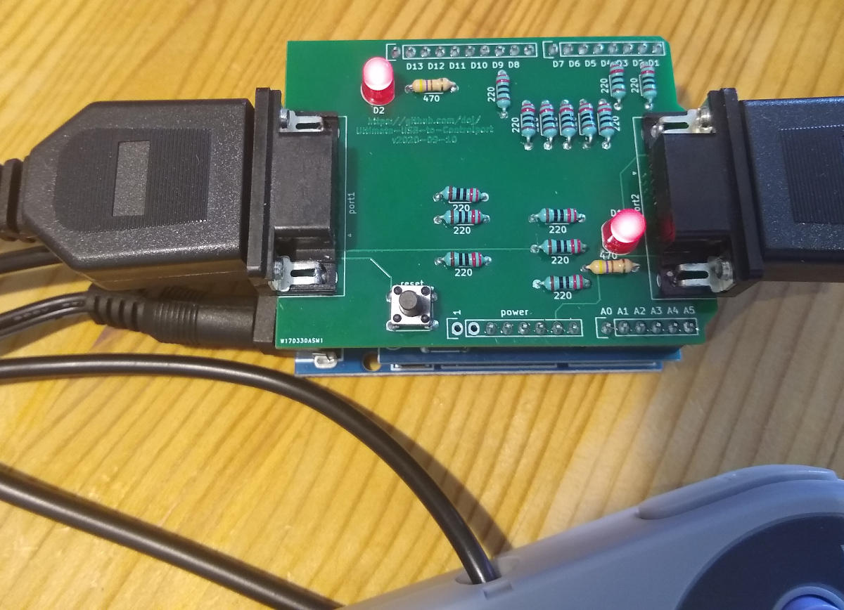
The following picture shows a build of the first version of the shield.
The following changes would improve the Arduino Uni Shield:
- increase distance of resistor pads
- use control port +5V to power the arduino. We need to protect against drawing too much current from the C64.
- design a new shield which can be plugged directly into a C64.
The following list shows which features are implemented.
- use digital x-pad for joystick directions.
- use B button for fire
- use X button for up direction
- use L button for left
- use R button for right
- use A button for auto fire
- use Y button for auto fire
- configure auto fire frequency
- use start button for fire 2 on POT Y
- use select button for fire 3 on POT X
- support two USB joysticks with both control ports
- lefty mode
- support mouse side buttons
- support PlayStation Classic USB controller
- use keyboard as joystick
- set keyboard numlock LED for each fire event
- switch joystick 1,2 and mouse 1,2 with button combination
- the USB controller should remember the button state and count how many button down pushes were made. However this is not so easy when autofire is selected. For example the following is buggy: press d-pad down, then X (up). When d-pad is released, both states are cleared.
- reconfigure any USB button to any Commodore button
- configure a USB button to set multiple directions at once. this could be useful for up+down and left+right to encode a special button.
- save configuration to Arduino EEPROM https://www.arduino.cc/en/Reference/EEPROM
- support PlayStation 3 controller
- support PlayStation 4 controller
- use analog joystick of a PlayStation 3 controller for POT X and POT Y
- support analog hat button
- support Xbox controller
- use USB mouse for POT X and POT Y with 1351 protocol
- support 1351 mouse wheel
- fix device mapping in USB Host Shield Library
- MIDI input
- burst fire mode, can also be used for one-shot fire mode
- fix 1351 analog jitter when USB data is received
The following controllers have been tested with the software:
-
Sony Playstation Classic USB controller.
-
iNNEXT SNES USB controller, which you also find under other brand names like kiwitata, retroflag.
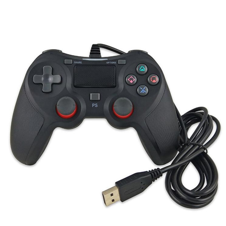
-
P4-5N USB controller, which costs ~USD20 in 2020 on Amazon.com
-
Microsoft Intellimouse optical USB.
-
Apple Mighty Mouse wired
-
generic 3 button + wheel USB mouse
-
generic USB keyboard


By default the serial debug console is enabled and uses 115200 baud. See the config.h file to configure the baud rate or to disable the debug console output.
-
the USB Host Shield 2.0 Library does not properly enumerate devices. This software currently works around that issue by using the universal HID device and manually parsing all incoming data packets. This may cause problems for untested USB HID devices.
-
1351 mouse support on POT is not working yet. When USB data is received the timer1 does not reliably work.
This software uses the arduino-timer library.
Information on Commodore 1351 mouse: http://sensi.org/~svo/[m]ouse/ http://www.zimmers.net/anonftp/pub/cbm/documents/projects/interfaces/mouse/Mouse.html
Information how to read joystick and POT on the C64: https://codebase64.org/doku.php?id=base:io_programming
Information on the USB protocol: http://www.usbmadesimple.co.uk/ums_4.htm
USB Host Shield 2.0 Library with fixes and better debugging messages: https://github.com/doj/USB_Host_Shield_2.0
PSX64 Interface The PSX64 interface connects Playstation controllers to most computers and consoles that use a DB9 joystick port.
PadSwitcher64 is an interface for SNES controllers and Commodore 64 control ports.
Unijoysticle 2 an interface for bluetooth wireless controllers and Commodore 64 control ports.
The following C64 Basic program can be used to test the 2 control ports and the POT of control port 1. You also find it in the GIT repository as joysticktest.prg
10 j = NOT PEEK(56321)
15 b = NOT PEEK(56320)
20 PRINT CHR$(147);
30 IF (j AND 1) THEN PRINT "1U ";
35 IF (b AND 1) THEN PRINT "2U ";
40 IF (j AND 2) THEN PRINT "1D ";
45 IF (b AND 2) THEN PRINT "2D ";
50 IF (j AND 4) THEN PRINT "1L ";
55 IF (b AND 4) THEN PRINT "2L ";
60 IF (j AND 8) THEN PRINT "1R ";
65 IF (b AND 8) THEN PRINT "2R ";
70 IF (j AND 16) THEN PRINT "1F ";
75 IF (b AND 16) THEN PRINT "2F ";
80 PRINT
200 POKE 56322,224 : REM disable keyboard
210 PRINT "POT1X " ; PEEK(54297) ; " POT1Y " ; PEEK(54298)
290 POKE 56322,255 : REM enable keyboard
1000 GOTO 10Write an email to Dirk Jagdmann doj@cubic.org The source code is hosted on https://github.com/doj/Ultimate-USB-to-Controlport
| Date | Changes |
|---|---|
| 2020-05-17 | 1351 fixes |
| 2020-09-29 | add Arduino Uno Shield PCB |
| 2020-09-30 | fix stuck direction when switching control ports |