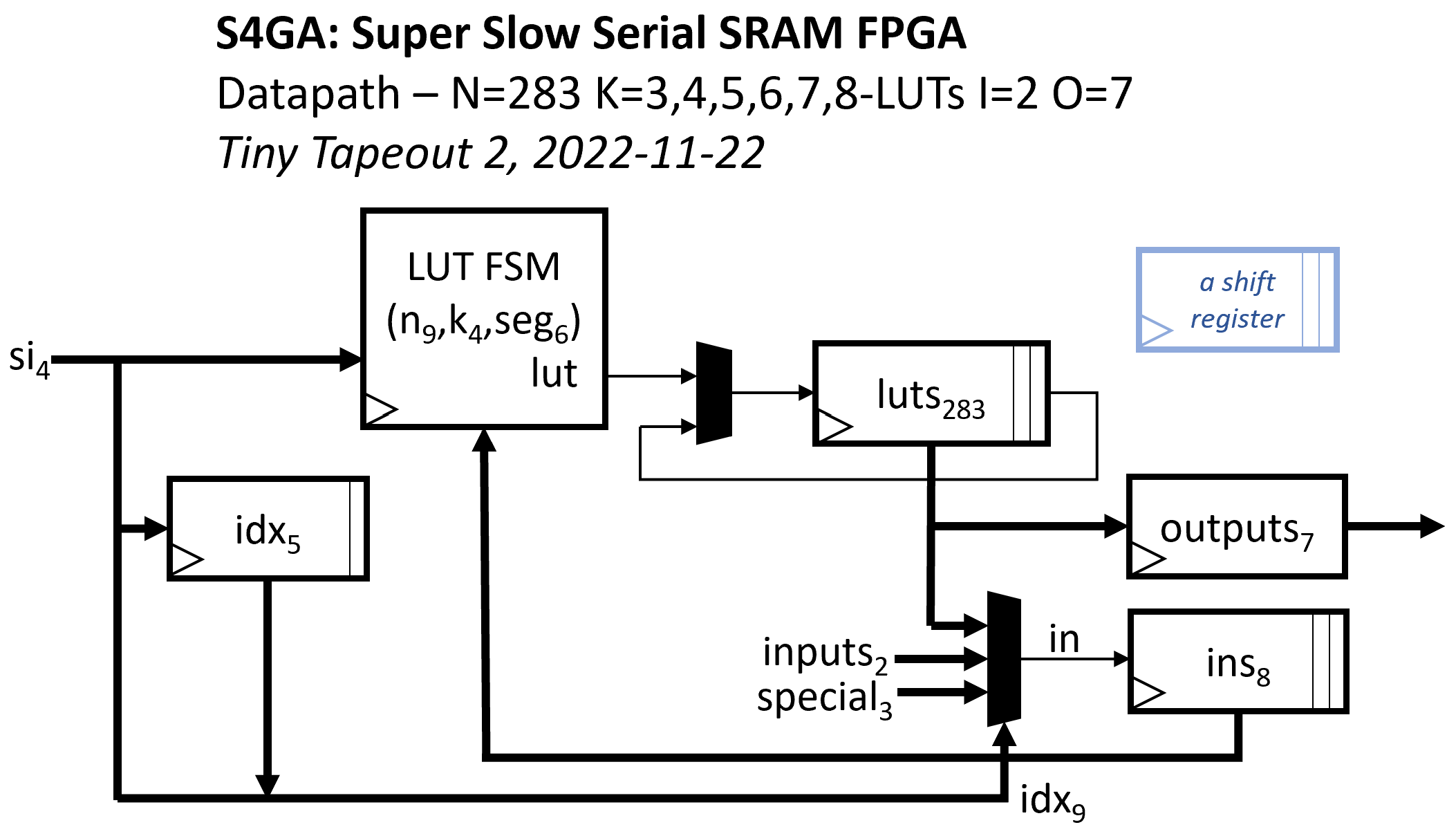
This is a copy for Tiny Tapeout 3 of a design that was submitted for Tiny Tapeout 2. I report below the original wiki.
This is the Tiny Tapeout 2 Super Slow Serial SRAM FPGA, S4GA, the best FPGA I could implement in ~150x170um of the 130nm Skywater ASIC PDK.
This version of S4GA uses an external serial SRAM with SQI (QSPI) mode such as the Microchip 23LC512 to continually stream in 4-bit segments of the LUTs' config data into the device.
While the LUT configuration data is streamed in from external SRAM, the current LUT output values are kept on-die.
As a circuit area optimization, the LUT outputs circular shift register 'luts' shifts every cycle, but LUT evaluation occurs every LL = K * ($clog2(N)+3)/4 + 2^K/4 cycles. So within the shift register, subsequent LUT output values are not continuous but permuted, each staggered by LL positions, interleaved and wrapping around.
To register the last N outputs without overwriting earlier ones, this requires GCD(N,LL)=1. Best to make N prime.
A given LUT output's index increments / wraps around to 0, each cycle. Therefore LUT outputs' LUT input indices in the configuration bitstream must compensate for these shenanigans.
The project is currently configured to repeatedly evaluate N=283 K=5-LUTs with LL=23 cycles. Each LUT configuration has this format:
// LUT config:
struct LUT { // all fields big-endian, most signif. nybble first:
    bit[12] in4;    // index of LUT input 4, in [0,3+I+N)
    bit[12] in3;    // index of LUT input 3, in [0,3+I+N)
    bit[12] in2;    // index of LUT input 2, in [0,3+I+N)
    bit[12] in1;    // index of LUT input 1, in [0,3+I+N)
    bit[12] in0;    // index of LUT input 0, in [0,3+I+N)
    bit[32] mask;   // 5-LUT truth table
};
While evaluating each K-LUT, S4GA also evaluates the LUT's lower half-LUT mask using the K-1 inputs in[0],...,in[K-2], into the 'Q' register. This enables efficient ripple carry adders, using the upper half-LUT to evaluate sum[i] and the lower half-LUT to evaluate the carry[i], fed into the next LUT (via Q).
Parameter I is the number of FPGA input signals. Currently I=2.
Parameter O is the number of FPGA outputs. Currently O=7.
The last O LUT outputs are copied to the io_out[6:0] output register, in each cycle in which evaluation of all of the N K-LUTs completes. On reset, io_out[6:0] is '0.
The first 3 + I LUT input indices encode special inputs and FPGA input signals. 0 => LUT input is constant 0 1 => LUT input is constant 1 2 => LUT input is Q 3 => FPGA input #0 ... => ... 2+I => FPGA input #I-1 3+I => a recent LUT output ... => ... 2+I+N => a recent LUT output etc.
All inputs are synchronous to clk. All outputs switch on clk and switch in the same cycle.
Pin         Signal  Description
io_in[0]    clk     external clock
io_in[1]    rst     +ve sync reset
io_in[2]    si[0]   LUT configuration lsb
io_in[3]    si[1]   LUT configuration bit
io_in[4]    si[2]   LUT configuration bit
io_in[5]    si[3]   LUT configuration msb
io_in[6]    in[0]   input 0 => LUT 0
io_in[7]    in[1]   input 1 => LUT 1
io_out[0]   out[0]  output 0 <= LUT N-I+0
io_out[1]   out[1]  output 1 <= LUT N-I+1
io_out[2]   out[2]  output 2 <= LUT N-I+2
io_out[3]   out[3]  output 3 <= LUT N-I+3
io_out[4]   out[4]  output 4 <= LUT N-I+4
io_out[5]   out[5]  output 5 <= LUT N-I+5
io_out[6]   out[6]  output 6 <= LUT N-I+6
io_out[7]   debug   debug: evaluated LUT input values, LUT output values
See also my prior Zero-to-ASIC S4GA repo.
- Implement yosys + bitgen based flow Verilog => configuration bitstream
More soon.
Copyright (C) 2022, Gray Research LLC. Licensed under the Apache License, Version 2.0.
TinyTapeout is an educational project that aims to make it easier and cheaper than ever to get your digital designs manufactured on a real chip!
Go to https://tinytapeout.com for instructions!
Edit the info.yaml and change the wokwi_id to match your project.
Please see the instructions for:
When you edit the info.yaml to choose a different ID, the GitHub Action will fetch the digital netlist of your design from Wokwi.
After that, the action uses the open source ASIC tool called OpenLane to build the files needed to fabricate an ASIC.
- Share your GDS on Twitter, tag it #tinytapeout and link me!
