Overview
If you want to monitor your energy usage
The P1_Meter is a a sensor device that:
- connects to your electricity meter's P1 port
- Reads the P1 output using one of the ESP32 hardware UARTs
- reads the OBIS coded information
- runs a CRC check on the received information to suppress incorrect readings
- translates the OBIS codes to readable topics
- publishes the information to a MQTT server on your network
- so you can read the information in HomeAssistant (or any other tool)
- uses mDns to simplify configuration and avoid the need for fixed IP addresses or static DNS leases
- allows the configuration to be changed though a simple config file
in addition it:
-
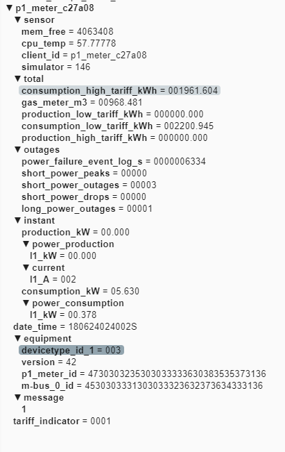
logs a few relevant sensors statistics to MQTT (client_id, free memory, CPU core temperature)
-
Allows you to view logs and other terminal output over wifi via the webrepl
-
Allows you to update update the configuration over the network using FTP
-
how does it work
[Diagram]
-
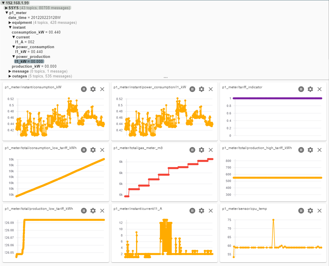
show me some pictures [a few screenshots / photos]
Hardware:
- Any ESP32 board no SPI ram is required, the firmware auto detects if it is present and runs on either.
- A single 1K Ohm resistor
- A cable with a 4 or 6 pin RJ12 connector (optionally a 4 pin RJ11 connector and be used)
- Some sort of casing
- Optional: a sort strip of 3 neopixels to use as indicators.
Firmware:
-
Use micropython 1.13 for or newer for the esp32 http://micropython.org/download/esp32/ you can download the firmware directly from
- ESP32 GENERIC-SPIRAM : esp32spiram-idf3-20200902-v1.13.bin
-
Install the micropython firmware to the ESP32 using the procedure documented in: Getting started with MicroPython on the ESP32 — MicroPython 1.13 documentation
-
the code in this repo; see the next paragraph.
- git clone this repo
- adjust config.py settings :
- homenet : WiFi SSID and Password
- broker : MQtt broker address, user and password
- RX pins to connect to the P1 Port
- Options (TX pin if you want to test drive without a connection to a P1 port)
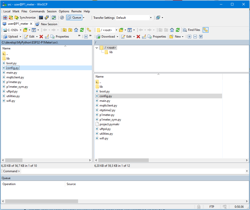
- upload code from /src folder to the board
- flash Micropython 1.13 or newer ( 1 time)
- upload the source code ( using pymakr or any other tool)
- reboot the board
the circuit is quite simple:
- ESP32, any devkit will do and will allow you to simply flash the Firmware and power the ESP by USB
- a 1K Ohm resistor , needed to stabilize the serial data by pulling it to +3.3 volt
- a female RJ-12 (or RJ11) connector, or you could solder a 4 wire phone cable directly to the board optionally
- some sort of case / box or container
- a small piece of perfboard , although if you want it should be able to solder directly on the devkit as well
- a string of 3 neopixel leds to provide status on Network , MQTT and the received P1 data, if you rather want a few simple leds to provide signals there are enough pins left , but switched to neopixels to simplify the wiring. the code should be in one of the earlier commits.
The ESP hardware UART 1 is used to connect to pin 2 ( you specify in config.py this allows normal functionality to use the USB port (UART 0) for configuration and monitoring of the ESP32.
The RJ12 connector in the electricity meter uses the following layout
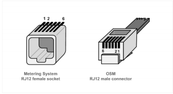
Connect the ESP32 to an RJ12 cable/connector using the below diagram.
Connection via straight 4/6 wire cable :
Note: This will reverse the pin numbers on the female connector that you are using
| RJ12 P1 | cable | RJ12 Meter | ESP32 Pin | RJ12 6w cable | 4w cable | comments |
|---|---|---|---|---|---|---|
| 1 - 5v out | ===> | 6 | 5v or Vin | [Optional] 1️⃣ | ||
| 2 - CTS | <--- | 5 | gpio-5 | blue | black | Clear to Send, High = allow P1 Meter to send data |
| 3 - Data GND | ---- | 4 | GND | black | red | |
| 4 - nc | 3 | - | green | |||
| 5 - RXD (data) | ---> | 2 | gpio-15 | yellow | yellow | 1K external pull-up resistor needed |
| 6 - Power GND | <=== | 1 | GND | [Optional] 1️⃣ |
1️⃣ max 250 mA When using a 6 pin cable you can use the power source provided by the meter.
If you are unsure which cable will be used to connect, or if you want to build some flexibility in your hardware design , it is possible to allow both cable types by :
- Output connecting both Pin 3 and Pin 4 Ground
this will ten allow you to swap the functions of pin 18 and 19 from
- CTS / RXD for a straight cable
- RDX / CTS for a cross cable
| RJ12 P1 | cable | Straight Cable | Cross Cable | - |
|---|---|---|---|---|
| 1 - 5v out | ===> | 1 | 6 | not connected |
| 2 - CTS | <--- | 2 | 5 | CTS / RXD software select |
| 3 - GND data | ---- | 3 | 4 | \ GND |
| 4 - GND data | ---- | 4 | 3 | / GND |
| 5 - RXD (data) | ---> | 5 | 2 | RDX / CTS software select |
| 6 - GND power | <=== | 6 | 1 | not connected |
I recommend that in this design you do not connect the Power 5v to your board
| ESP32 Pin | Color | Female Connector |
|---|---|---|
| GND | black | pin 4 & 3 |
| gpio-2 | pale blue | pin 5 |
| gpio-5 | yellow/blk | pin 2 |
3 Neopixel Leds (top to bottom):
| led | purpose | Red | Green | other |
|---|---|---|---|---|
| 2 | P1 meter | CRC Error | CRC OK | Blue: data received , Purple : Simulator sending Data |
| 1 | mqtt | Not connected | Connected to MQTT broker | Yellow: Data could not be send to Broker |
| 0 | wifi | Not connected | IP address acquired |
Please adjust the relevant settings in config.py
# Serial Pins for meter connection
# TX pin is only used for testing/simulation but needs to be specified
RX_PIN_NR = const(2)
TX_PIN_NR = const(15)
RTS_PIN_NR = const(5)

# Base SSID to connect to
homenet = {'SSID': 'IoT', 'password': 'MicroPython'}

#the mqtt broker to connect to
broker = {'server': 'homeassistant.local', 'user': 'sensor', 'password': 'beepbeep'}

HOST_NAME = b'p1_meter_' + hexlify(unique_id())
ROOT_TOPIC = b"p1_meter"

#also publish telegram as json
publish_as_json = FalseAssuming that you have cloned the repo to your PC , and have updated the configuration file config.py .
You will need to transfer the updated configuration file to the ESP32.
You can do this via serial connection, or as the P1_meter and your pc are likely in in different locations you can do this over WifI
The MicroPython webrepl is started as part of the standard configuration, and advertises itself as p1_meter.local using the standard webrepl port (8266).
If you are on the same network , this allows you to connect to the P1_meter to verify its operation.
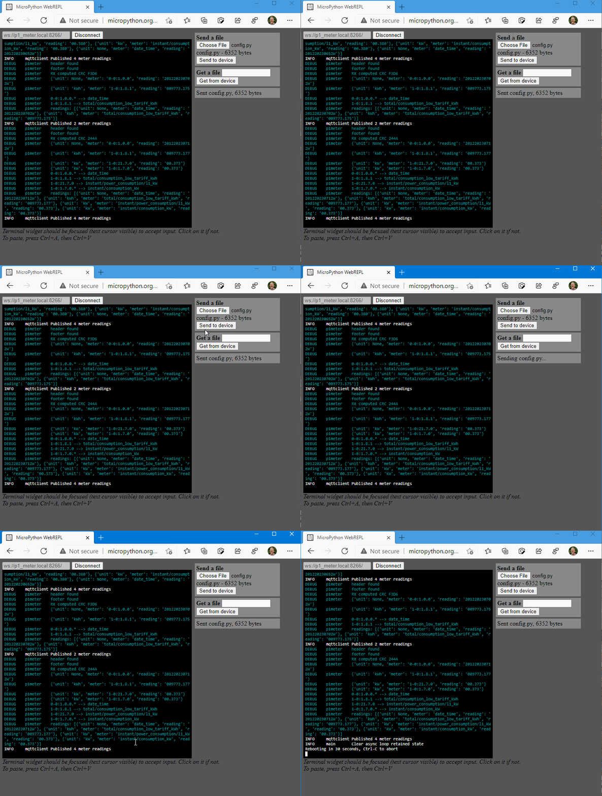
The below link uses the hosted webrepl, and specifies the board to connect to. http://micropython.org/webrepl/#p1_meter.local:8266/
-
[Connect] to the board
-
Enter the current webrepl password. default: p1meter
-
Select the config.py file to upload
-
click [Send to device]
-
Click in the terminal window
-
Press Ctrl-C once, to interrupt the running instance. You should see something like the below, and the 3 leds will turn red
INFO mqttclient Published 4 meter readings INFO main Clear async loop retained state Rebooting in 30 seconds, Ctrl-C to abort -
the device will automatically reboot in 30 seconds, and the new configuration will be activated.
- git client
- python 3.x installed
- vscode
- pymakr extension
- pip install micropy-cli
As the software is written in Micropython building is not needed. if you really want or need to minimize the footprint on the device you can pre-compile the .py files to .mpy using the micropython cross-compiler
You can run the built-in simulator for testing (using TX_PIN_NR)
- connect the rx and tx pins with a wire
  # Serial Pins for meter connection
  # TX pin is only used for testing/simulation but needs to be specified
  RX_PIN_NR = const(2)
  TX_PIN_NR = const(15)
  CTS_PIN_NR = const(5)

  #------------------------------------------------
  # A few Leds - optional
  NEOPIXEL_PIN = const(13)
- edit the configuration file `config.py` to enable the Simulator
RUN_SIM = TrueThe p1 meter comes with a built-in test and simulation mode that allows you to test and change the software, without needing to physically connect it to a electricity meter.
this simulation mode can be enabled by wiring, or by making a change to the config.py file
To enable this via wiring:
- Connect Pin 18 --> GND , enable Simulator
- Connect Pin 15 --> Pin 2 , connect simulator TX to RX
By default:
- the root topic is changed
- a fake P1 message is generated every 10 seconds on Pin 15
- this message has a few random values added to it
- the CRC16 is calculated before sending
- the message is passed of the serial connect ( see .2 above) to the input
- the message is is processed by the normal software and sent to mqtt using a different root topic to avoid interfering with actual input..
To change the fake message see p1meter_sym.py
