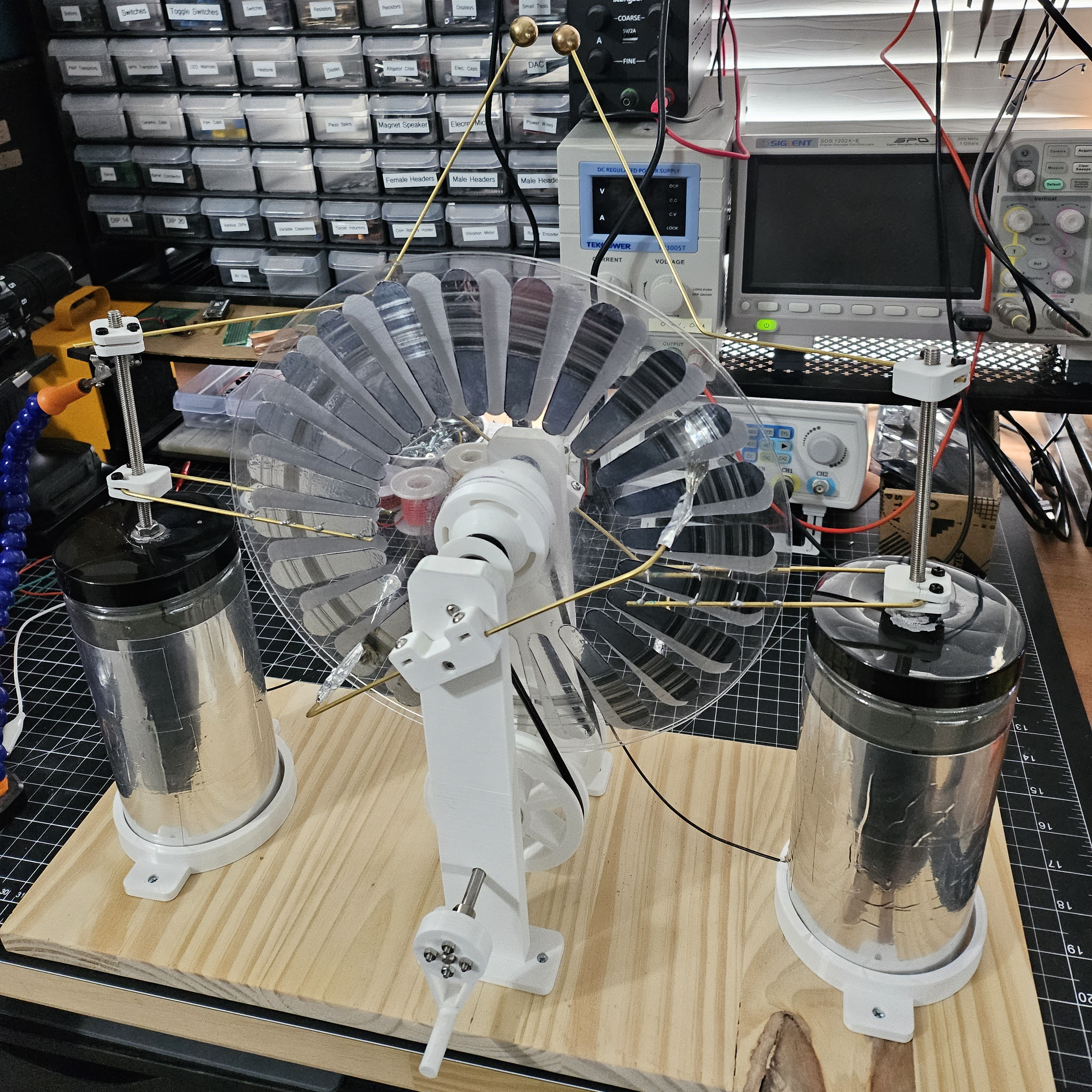
A Wimshurst machine made to learn about electrostatic generators.
I had trouble recording it, but the best I could get was a half inch spark gap. 1 inch spark gap is about 30kV, so I guess I generated about 15kV. I wish I could get a better spark gap, but I'm satisfied enough with the result and ready to move on.
- 2x 10 inch clear acrylic disc
- 6x 606 bearing
- 2x 15mm brass bearing
- 2x M6 threaded rod
- 2x M6 304 stainless steel rod
- 3x 6mm flange coupling conector
- 4x 2mm brass rod
- 1x 4mm polyurethane belt
- 2x Salwater leyden jars
- 8x Flat head #4 x 1/2"
- 3mm nylon bolts and nuts
- Aluminum foil tape
- 8" x 20" wood board
- 3D printed parts
This project got away from me...I meant to write down each step as I built it. But, building this took longer than I expected and I got distracted by other projects. So, this next part is not very helpful.
I used mainly M3 nylon bolts and nuts to prevent charge from leaking out. Unfortunately, I was not smart enough to actually write down the bolt lengths I used and they are not really reflected in my design. I need to get better about adding this type of stuff to my Fusion 360 projects.
For each support, I press fit a 606 bearing into cad/support-bottom.stl and cad/support-top.stl. Then I superglued them together.
For each disk, I used a 10 inch clear acrylic disc and drilled a 6mm hole in the center. I used cad/electrode-template.stl to trace an outline for 24 electrodes on aluminum foil tape. Then I positioned them equally around the disk using a protractor.
The axles were cut from M6 304 stainless steel rod. The top axle is ~13mm and the bottom axle is ~20mm.
For each disk pulley, I press fit a 606 bearing into cad/disk-pulley.stl and super glued it to a disk. Each cad/disk-pulley.stl is mounted to the top axle.
The drive belts are made from 4mm Polyurethane belt. I cut them to size (forgot to record this) and used a soldering iron to re-weld the belts. One belt has a twist in it, to ensure the belts rotate in opposite directions.
For each drive pulley, I mounted it to the bottom axle using a 6mm flange coupling conector. The belts are setup between each cad/disk-pulley.stl and cad/drive-pulley.stl.
The cad/hand-crank.stl is fixed to the bottom axle using a 6mm flange coupling conector.
For each collector, I bent 2mm brass rod in a U shape and soldered small spikes of wire pointing inside. This bent rod gets clamped into cad/collector-mount.stl using nylon bolts and nuts.
For each neutralizer, I bent 2mm brass rod and clamped it into cad/neutralizer-v2.stl using nylon bolts and nuts. Then I taped stranded wire to each end of the neutralizer using aluminum foil tape.
For each electrode, I bent 2mm brass rod and clamped it into cad/neutralizer-v2.stl using nylon bolts and nuts. I drilled a ~2mm partial hole into each 15mm brass bearing and super glued it to the end of the bent rod.
For each leyden jar, I built a saltwater leyden jar using my instructions in bytes/electrostatics/leyden-jar. To ensure position, the leyden jar is placed in a cad/leyden-jar-mount.stl. A wire is also connected between each leyden jar on the outside foil.
Other things I made while building the Wimshurst machine.
