Introduction
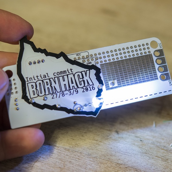
The badge for the Initial Commit of Bornhack is designed to be hacker friendly and simple enough for everybody to play with.
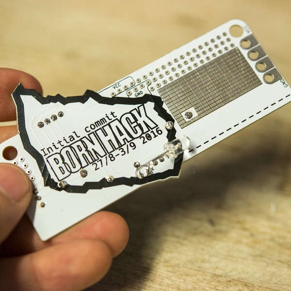
It comes as a kit, that you should solder yourself (there are only 18 solder joints) and in it's base configuration it can function as a name tag and a small flashlight.
The prototyping area on the badge is inspired by the very simple badge from the Hackaday Super Conference, that motivated people to come up with crazy addons for their badge hacking.
Assembly instructions
The badge has circuitry for a so called Joule Thief, that can be used to light up a white LED using a single AA battery, that will be considered used in pretty much all other electronics products. You can also put in a new battery, and then the LED can stay lit for a very long time.
If you want to be creative and hack your badge, you can see the below guide simply as a suggestion and decide yourself on which components to use and how to use them. There is also plenty of prototyping area on the badge, for you to mount other components and modules, more on that in the hacking section below.
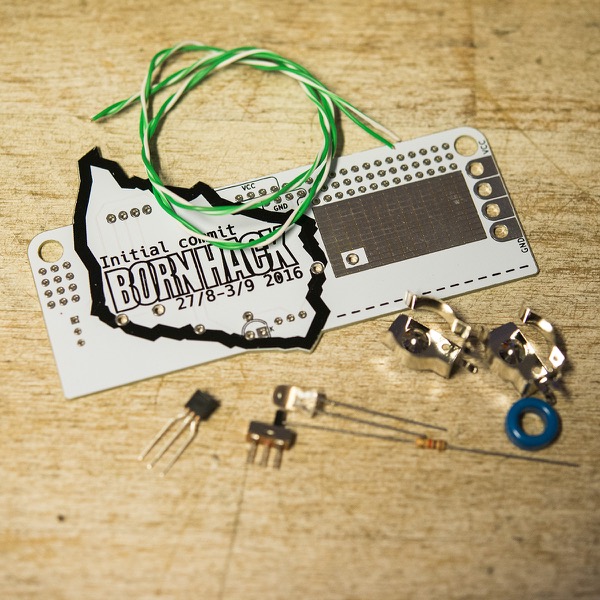
Parts list
- 1x Printed Circuit Board (PCB)
- 1x Transistor (BC547B)
- 1x LED (white, 5mm)
- 1x Resistor (1K ohm, brown, black, red, gold)
- 2x Battery clips for AA battery (BK-92)
- 1x Switch (SPDT)
- 1x Ferrite core toroid (900nH, N87, 10.8mm diameter)
- 2x 30cm wire (solid core, different colors)
Tools needed for Assembly
- Soldering iron
- Solder (~0.6mm is probably easiest)
- Side cutter
Putting the simple components on
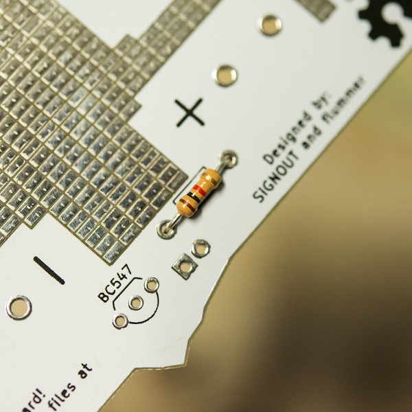
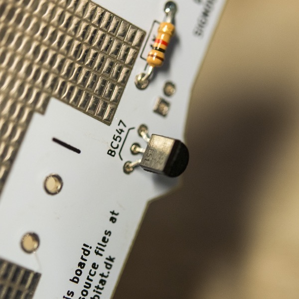
You can start out by putting the simple components on. First one are the resistor, which does not have a specific polarity, so it can be mounted in any direction, and it has to go over the little box with a "1K" inside. You start by bending the leads, insert them through the holes and on the other side of the PCB, move the leads away from each other, so that the component doesn't fall out.
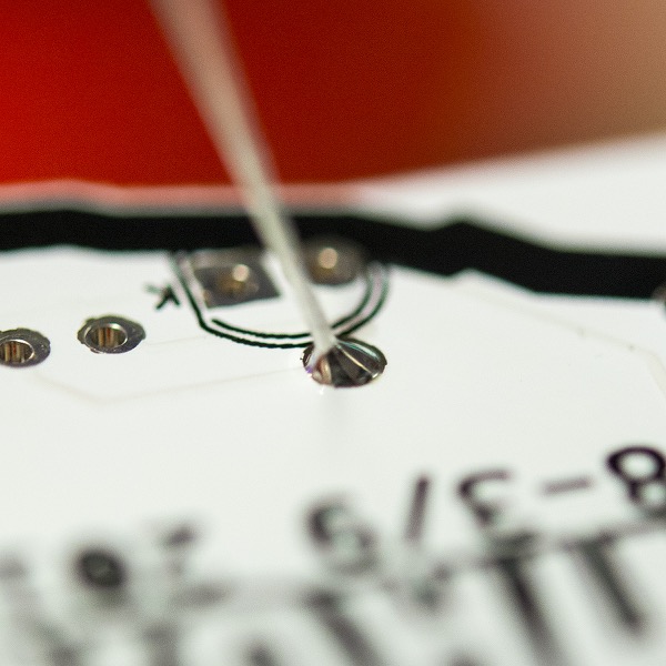
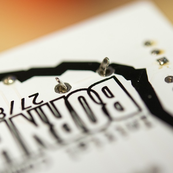
You are now ready to solder the first component. Start by placing the tip of the soldering iron so that it touches both the resistor lead and the small ring around the hole on the PCB. This will heat up both of these and a few seconds later, add in a bit of solder. you only need about 5-10 mm of the solder (if your solder is thicker, you will need less). Remember to pull back the solder before removing the soldering iron, since otherwise, your solder will be stuck to your board.
A good solder connection will have sort of a volcano shape, with a nice curve between the PCB and the lead. If your solder looks like a ball on top of the PCB, you probably have a bit too much solder, or haven't properly heated up the pad on the PCB.
When you have soldered both of the leads on the resistor, you can cut off the excess with a side cutter just above the PCB.
Moving on to the switch
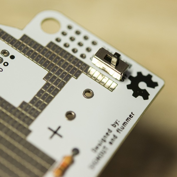
Now it's onto the power switch. It's symmetrical, to this isn't picky about orientation either. It's actually the traces on the PCB that decides what is on and what is off.
Regarding the soldering, it's the same procedure as the resistor, but be careful, not to heat up too much, because the switch has plastic parts inside that will melt if you continue heating it up. It can be a good idea to only solder one of the pins first, and then check that the switch sits correctly. If it's a bit crooked, it's much easier to fix it before you solder the other two pins.
Transistor
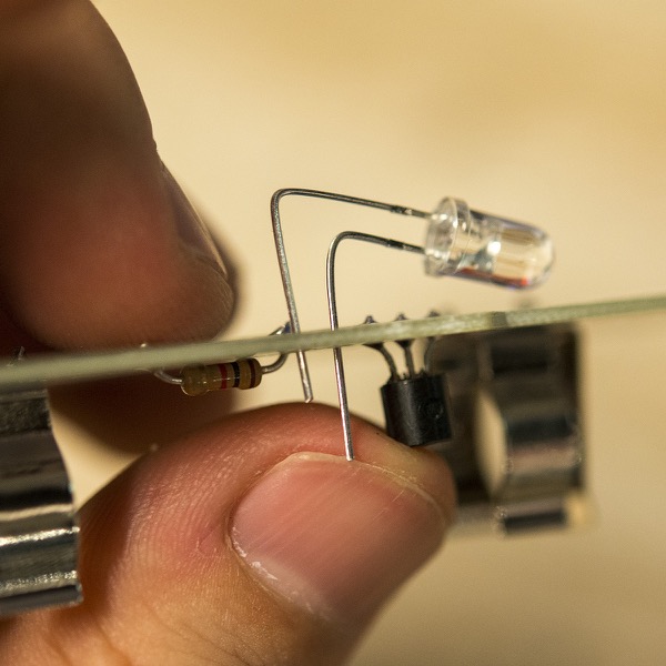
After the switch, it's time to do the transistor. This component has to go in the right way, otherwise it won't work. You can see the orientation on the PCB, where the shape of the transistor is drawn using the silkscreen. The transistor should not be put all the way down to the PCB, it's OK that is sits a few mm above.
Battery clips
Then it's time to put in the battery clips. These of course have to sit with the opening towards each other you have to press them firmly into the holes, so that the bottom of the holders are flush with the PCB. You don't need to bend the legs of those, they should snap in and hold the clips in place while you solder them. These can take quite a bit of solder, and those joints will also be the mechanical connection to hold the battery.
LED
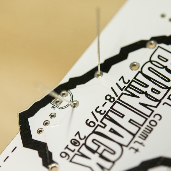
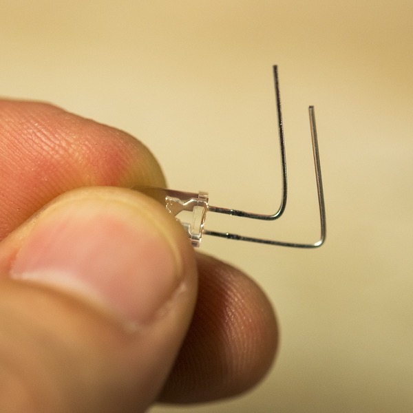
Now we have gotten to the LED. Depending on what you would like to light up, you can bend the leads on the led, so that it points in a certain direction. But you should be aware, that the polarity of the LED is important. If it's mounted the wrong way, it won't light up. Similar to the transistor, the LED also have a flat side, but it's not as obvious as on the transistor, but it is there and you should be able to feel it around the bottom of the clear plastic. The silkscreen on the PCB has a similar flat marking for the LED and that is also marked with a "K" for cathode. Another indication on how to orient the LED is that one lead is shorter than the other. The short one is the cathode and the long one is the anode, but if you start bending the leads, it can be a little tricky to see which is the long and which is the shorter one.
An easy hack is to replace the LED with eg. a blue one. There are only white LEDs in the kits, but if you have a blue one, you can use that.
Coil
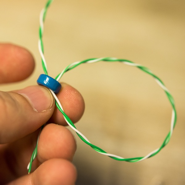
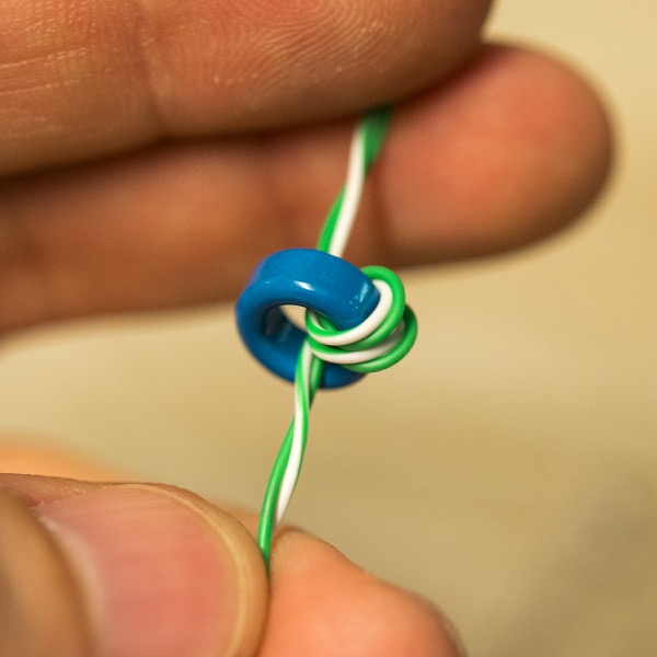
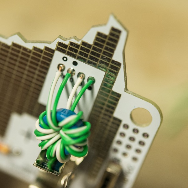
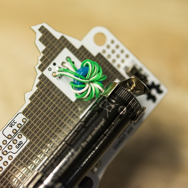
Now it's time for the coil. You first have to wind it yourself, and you do that with the two wires. The wires are already twisted together and you don't need to untwist them, since you simply need to coil both wires at the same time. You will probably be able to fit something like 6-8 windings, but it's not critical exactly how many you have, just continue until you can't fit any more through the center of the toroid. There is plenty of wire, so make sure you have a bit extra in both ends.
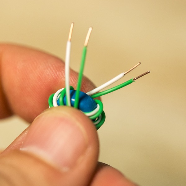
When you are done coiling up the wire, the most tricky part is ahead of you. You have to trim the wires, and remove the isolation. This can be a little tricky and you have to do it without cutting the wire 4 time in a row, so use some of the extra wire to do a bit of practice, before trimming the wires to the correct length, which is roughly 10-15 mm from the coil. Then remove the isolation about 5mm in. on all the 4 wires.
You should now have 2 wires coming out from one side of the toroid and 2 on the other side, and there should be one of each color on each side.
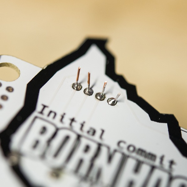
The little dots on the PCB indicate which wires has to go where.
Test
If you have come this far and haven't made any solder bridges or other short circuits, it's time to insert the battery and turn on you badge. If everything went well, the LED should turn on, if not, it's time for some debugging.
Hacking the badge
Having a badge that can light up your name or maybe also you tent an night is of course super awesome, but customizing it to do other things is even better.
The badge has both though hole prototyping area and SMD (surface mount) area for you to add components or modules.
Most of these pads are not connected to anything, so you can design your circuit as you wish, but to help out a bit, there are both a GND net and a VCC net. The GND net is connected to the negative side of the battery, and if you want VCC to be connected to the positive side of the battery (after the switch), you can put a solder blob on the little jumper in between "BAT" and "VCC". You can have a look at the board file for further info on this. In addition to the through hole pads that are marked with VCC and GND, the top and bottom row of the SMD pads on the front are also VCC and GND respectively, and connected to the large terminals on the side.
The middle terminals are simply connected to the SMD pad sitting right next to them. If you look closely or in the board file, you can see the connections. The SMD area on the back has similar connections to VCC, GND and the two middle terminals.
Pad spacing
The through hole pads are spaced on a 100mil/2.54mm (1/10 inch) grid and the SMD pads are using the same 100mil grid in the x-direction but using a 50 mil/1.27mm (1/20 inch) grid on the y-direction, to make it a bit more compatible with SMD chips and other small components.
There are many different footprints for chips and many are way smaller than this. If you want to use one of those, the recommendation is to either use a breakout board or place the chip "dead bug" style and solder thin wires to the leads.
Inspiration / Ideas
There are many things that can be attached to an electronic badge. The Joule Thief circuitry can't really power a micro controller or similar as it is, but one option for an alternative power source is a 3.7v 14500 Li-Ion cell, that has the exact same size as an AA battery. The Joule Thief circuitry will, over time, destroy one of those cells, if put on directly, but with a bit of support components, it could be an option.
If you manage to get a micro controller up and running, adding things like small screens, more LEDs or maybe a radio module (WiFi, BlueTooth, LoRa, etc.) should be fairly easy.
PCB Design files
The PCB has been designed in KiCad and both the schematics and the board files are available for you to examine and build on.
License
The badge design is licensed under Creative Commons, Attribution Share-Alike (CC-BY-SA). Please use the design and built your own. We would love to see what you make.
The BornHack IoS Badge (Missing wifi and battery) by @-boy
So the idea of this badge hack is to add the ESP8266 Wifi module to the badge to make it part of the Internet of Shit, by also adding a screen and some LEDs the badge will be able to display some info like name or talk info and blink to warn when a new talk is about to take place
Also the plan is to add some tactile buttons for direct user input, one of the buttons will be to make the ESP8266 create a Wifi AP or turn it off if it is on
With 3 input buttons it would also be possible to make a menu system for even more advanced direct user input
The 8x Red LEDs at the top is planned to show the strength of the wifi network the badge is connected to, but can also be used for other things
The 3x Green LEDs are thought to just light up all the time and then blink if the users attention is needed
Besides direct user input, the idea of having it as a IoS device is that it can be reached and configured this way
Also the wifi connectivity is thought as a way for people to send messages to eachother
Components
- 1x ESP8266 12E
- 1x Arduino Nano
- 2x Green LEDs
- 8x Red LEDs
- 1x OLED display compatible with Adafruit SSD1306 driver
- 3x tactile buttons (not implemented yet)
Leasons learned and what is working
A couple of things I have learned during the week at BornHack working on the badge hack
- 5v is not 3.3v, this is realy important
- Start with lower goals
- Iterate in small steps with something that works each iteration
Right now the badge can show stuff on the OLED display, but wifi is not working have had some issue with ESP8266 firmware which I worked on most of the week, got basic firmware to work with AT command over serial, so right now the plan is to have a Ardunino to control everything and communicate with the ESP8266 but the Arduino runs 5v so missing components to talk with the 3.3v ESP8266, and lastly it is missing a portable power source and it is quite bulky right now
