24Hr digital clock using 8051 and RTC DS1307
Program is written in Assembly Language on Keil uVision 5 and simulation was done on Proteus 8.9 using AT89C51
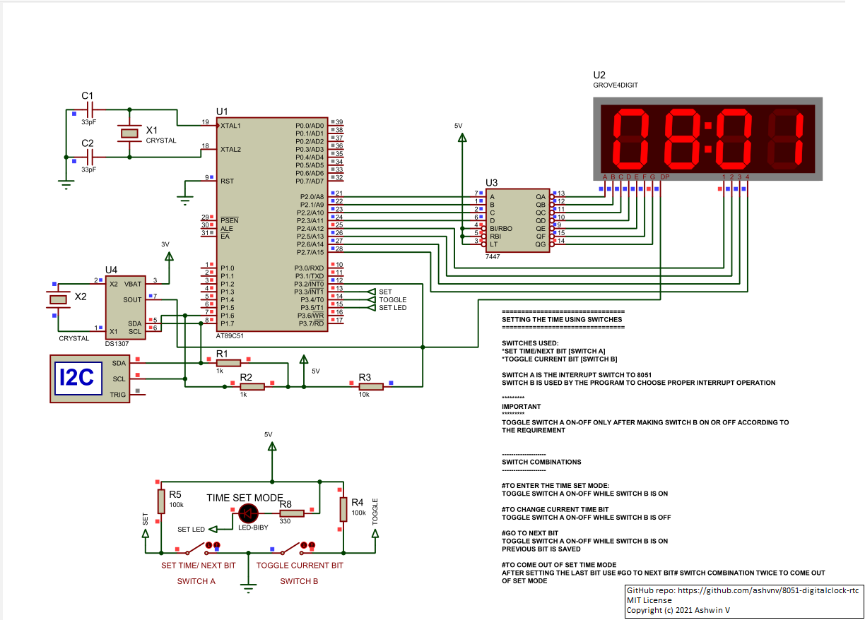
Operation of the clock in brief:
I2C protocol is used for communication between 8051 and DS1307. Initially 8051 enables the 1Hz Clock output on RTC chip. This 1Hz clock is used to interrupt 8051 every second. 8051 does not keep the track of time but instead outsources it to the RTC chip. At each interrupt, 8051 reads the time information present in the RTC chip and updates it's own time registers which is used to show information on the Groove 4 digit 7 segment display. 7447 BCD to 7 segment display is in multiplexing configuration for driving 4 7-seg display simultaneously. Switch bouncing is ignored in the simulation. Use debounce circuit while practically implementing the project.
RTC time can be manually adjusted using the Time Set Mode Switches, Switch A and Switch B
Switches used:
- set time/next bit -> switch A Interrupt switch to 8051
- toggle current bit -> switch B Used by the program to choose proper interrupt operation
Important: Switch A is the interrupt switch. Interrupt program determines what operation to do based on the state of switch B. So make switch B on or off according to the requirement before toggling switch A
To enter the time set mode:
- Toggle switch A on-off while switch B is on
To change current time bit
- Toggle switch A on-off while switch B is off
Go to next bit
- Toggle switch A on-off while switch B is on
- Previous bit is saved
To come out of set time mode
- After setting the last bit use #go to next bit# switch combination twice to come out of the time set mode
-
R1 -> ACCUMULATOR BACKUP
-
R2 -> MICRO_DELAY FUNCTION
-
R3 -> TEMPORARY STORAGE IN TIMESETMODE SUBROUTINE
-
R4 -> HOURS REGISTER
- 0x(MSB)(LSB)
-
R5 -> MINUTES REGISTER
- 0x(MSB)(LSB)
-
R6 -> STORE WHICH TIME SET MODE 8051 IS CURRENTLY OPERATING
-
0x00: Normal Mode -
0x01: MSB HOUR SET -
0x02: LSB HOUR SET -
0x03: MSB MINUTES SET -
0x04: LSB MINUTES SET
-
- (150H)SETTIMEMODE -> INT1 CALLS THIS ADDRESS FOR MANUALLY SETTING TIME
- (260H)DISPLAY -> 8051 DRIVING 7447 BCD TO 7SEG DISPLAY DECODER IN MULTIPLEX MODE
- (300H)UPDATETIME -> CALL TO UPDATE 8051 INTERNAL TIME REGISTERS R4 AND R5
- (2F0)MICRO_DELAY -> CALL A SMALL DELAY
- (400H)RTCTIMEUPDATE -> CALLED WHILE MANUALY UPDATING TIME IN RTC CHIP
- (510H)RSTART -> I2C RESTART CONDITION
- (520H)STARTC -> I2C START CONDITION
- (530H)STOP -> I2C STOP CONDITION
- (540H)SEND -> I2C SEND DATA
- (600H)ACK -> I2C ACKNOWLEDGEMENT (M TO S)
- (610H)NAK -> I2C N-ACKNOWLEDGEMENT (M TO S)
- (620H)RECV -> I2C RECEIVE DATA