This is a set of example and template projects for bare-metal applications on the STM32MP15x Cortex-A7 microprocessor. I use "Bare-metal" to mean no OS, so unlike most STM32MP1 or Cortex-A tutorials, there is no Linux or RTOS. Basic systems such as handling interrupts, setting up a stack, memory management, are handled in these projects, as well as more advanced featues like parallel processing (multiple cores) and coprocessor control.
The target audience is the developer who is already familiar with the Cortex-M series. Rather than give a ground-up introduction to microcontrollers/processors, these projects assume you are familiar with MCUs such as the Cortex-M0/M3/M4/M7 or perhaps AVR (ATMEGA) chips. You should be comfortable with the concepts of interrupts, stacks, HAL, etc. If not, you'll need to brush up on microcontroller fundamentals before proceeding.
Most of the code is in modern C++, with some assembly thrown in there where needed. You don't need to know C++ or assembly, the projects are very simple and should be easy to follow.
I am actively refining and adding new example projects to this. If you want to see something, please ask! (open a github issue)
Here's a list of the example projects:
- Minimal Boot: Hello World project to prove the bootloader and your hardware is working.
- Ctest: Demonstrates the startup code for a C/C++ project: setting up the stack, initializing globals, etc.
- Basic IRQ: Basic interrupt handling with the A7's Generic Interrupt Controller.
- Nested IRQ: More sophisticed interrupt handling: interrupts interrupting interrupts! (and using lambdas as handlers!)
- Multicore_a7: Demonstrates running both A7 cores in parallel.
- Copro_rproc: Using the rproc feature of U-Boot to load and run firmware on the M4 core in parallel with the A7 core.
- Copro_embedded: Embedding the M4 firmware binary into the A7's firmware binary, and loading it on demand. Wacky, but cool.
- Audio Processor: A fun practical project that lets you select one of several audio synths to play. Requires STM32MP1 Discovery board. Uses STM32-HAL, some DaisySP example projects, and some Faust algorithms. TODO: use multi-core A7.
The STM32MP157 is a powerful chip, with two Cortex-A7 cores running at 650MHz or 800MHz, L1 and L2 caches, up to 1GB of external 533MHz RAM, a Cortex-M4 core and a suite of peripherals. The peripherals are familiar to anyone having used the STM32F7 or STM32H7 series (and sometimes STM32 HAL-based F7/H7 code can be used as-is in the MP1 A7).
Each project in the examples/ directory is meant to demonstrate a simple idea
with as few dependencies as possible. The CMSIS device header for the
STM32MP157 chip is used to access the hardware registers, and in some cases
I've written a simple driver class that lives in examples/shared/drivers/.
There also is some shared initialization code in examples/shared/system/,
such as setting up the MMU and the caches. For the most part you can use these
as-is for most projects (although you will need to modify the MMU setup if your
project needs areas of RAM to be non-cacheable in order to use a DMA, for
example). I plan to do a tutorial on the MMU eventually.
U-Boot is a third-party tool that we use for the bootloader (don't worry if
you're not familiar with U-Boot!). The U-Boot bootloader must be built once,
and loaded once onto an SD card, which is inserted into the board. You
probably won't need to think about it ever again after that, unless your
hardware changes substantially (or you run the corpo_rproc example project).
The application ultimately needs to live on the SD card as well, but it can be flashed into RAM using an SWD flasher, making debugging much easier than having to copy files to an SD card each time the code is changed.
You need:
- Any STM32MP15x Discovery board, or an OSD32MP1-BRK board
- A computer with the arm-none-eabi-gcc toolchain installed (v8 or later)
- Various common USB cables, depending on which board you select
- A micro SD card
- A USB-to-serial cable (only if you use the OSD32 board) such as the FTDI cable
- Optionally, a J-link or ST-LINK debugger (only if you use the OSD32 board)
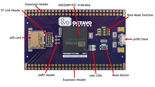
Octavo OSD32MP1-BRK board
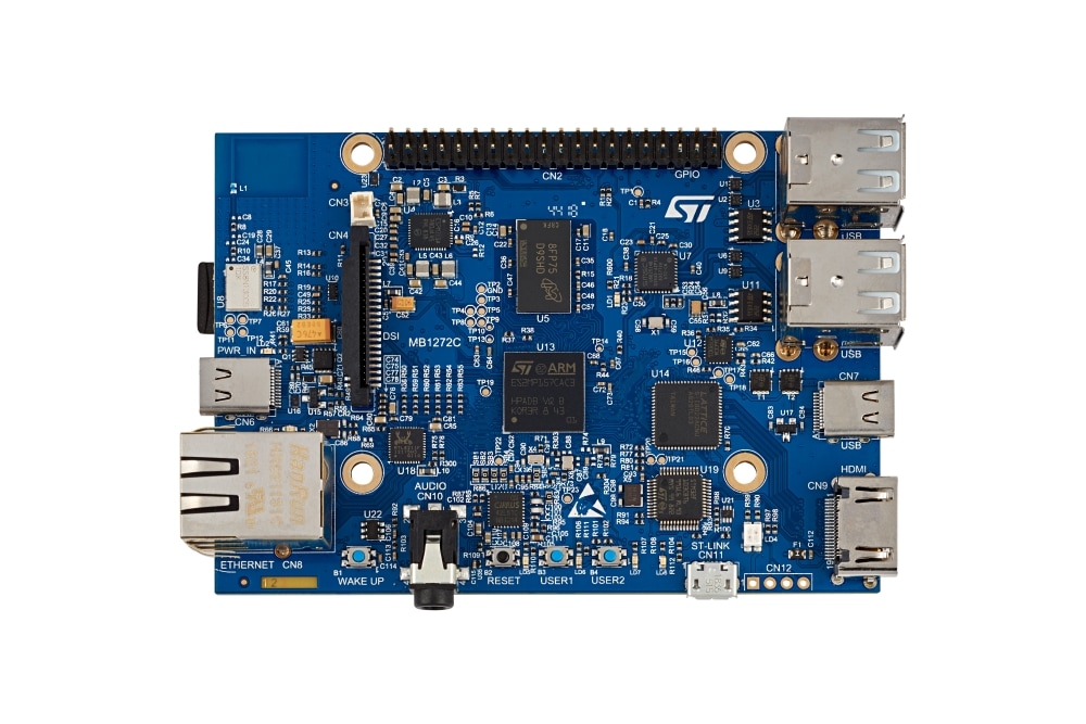
These projects will build and run on any of the STM32MP15x Discovery boards, or the OSD32MP1-BRK board. The OSD32MP1-BRK is simply a breakout board for the OSD32MP15x SiP, which is an STM32MP15x chip plus SDRAM and PMIC and other stuff in a BGA package.
The OSD32MP1 board is cheaper and has SWD connection for debugging, but you'll need a USB-to-UART cable to use it. The Discovery boards have a built-in USB/UART and a lot more stuff on the PCB (codec, buttons, ethernet jack, HDMI, an option for a DSI screen,...). These example projects work the same on either board (you only need to build the bootloader slightly differently).
You'll need an SD card to insert into the board. And some USB cables (micro, USB-C).
If you choose the OSD32MP1-BRK board, you can take advantage of the SWD header by using an SWD programmer, like the SEGGER J-Link, or an ST-LINK to debugging with gdb. The board has a 10 exposed pads designed to fit a 10-pin pogo adaptor, such as this one from Tag-Connect or Digikey. While you're shopping, pick up these helpful accessories too: retaining clip , and 20-to-10-pin-adaptor. The Discovery boards lack any header for SWD, and there's not even an easy place to solder one on.
Also if you use the OSD32MP1-BRK board, you'll need a USB-to-UART cable. This is built into the Discovery boards, so you don't need it for them. The OSD32 board has UART pins exposed, and you can solder header pins and connect such a cable. FTDI makes the TTL-232R-3V3, available from Digikey, or there are other options like a host adaptor such as the Binho Nova.
Clone the repo:
git clone https://github.com/4ms/stm32mp1-baremetal
On macOS, you may need to install gsed and set your PATH to use it instead of
sed. This is needed for building U-Boot. See Caveats section in brew info gnu-sed for details.
brew install gnu-sed
export PATH="/usr/local/opt/gnu-sed/libexec/gnubin:$PATH"`  ##or add it to your .zshrc/.bashrc
I've added some pre-built images for U-boot, so you can up and running more quickly. If you want to use the pre-built images, skip the next step.
Build U-Boot using the script. The output will be in third-party/u-boot/build/:
cd stm32mp1-baremetal
scripts/build-u-boot.sh
The script will prompt you to enter the board you selected. Depending on your selection, the script will set a value for DEVICE_TREE when building U-Boot. Note: Ignore warnings about "format string is not a string literal", it happens with some arm-none-eabi-gcc versions
Verify the output files were created:
ls -l third-party/u-boot/build/u-boot-spl.stm32
ls -l third-party/u-boot/build/u-boot.img
Now you need to format and partition an SD card. Insert a card and do:
## Linux:
mkfs.fat -F 32 /dev/sdX

## MacOS:
diskutil eraseDisk FAT32 BAREMETA /dev/disk#
Where /dev/sdX or /dev/disk# is the actual device name, such as /dev/sdc or /dev/disk3.
If you need to find out what the device is, you can type ls -l /dev/sd or ls -l /dev/disk and then hit Tab.
Or, on macOS you can type mount instead of ls -l /dev/disk<TAB>
Take note of what it lists. Then remove (or insert) the SD card, and repeat the command. Whatever changed is the SD card's device name(s). Use the base name, e.g. /dev/sdc, not /dev/sdc3.
You also could use the script format-sdcard.sh, though it's just a heavy wrapper around the above commands.
I recommend you eject and re-insert the card at this point (you might get some cryptic errors if you don't).
Then run the script to partition the drive
scripts/partition-sdcard.sh /dev/XXX
...where /dev/XXX is the SD card device name such as /dev/sdc or /dev/disk2 This script will create four partitions, and format the fourth to FAT32.
Then run the script to copy the bootloader (u-boot and spl) to the first three partitions:
# To use pre-built images for OSD32MP1 board:
scripts/copy-bootloader.sh /dev/diskX third-party/u-boot/images/osd32mp1-brk/

# To use pre-built images for STM32MP157A-DK1 Discovery board:
scripts/copy-bootloader.sh /dev/diskX third-party/u-boot/images/stm32mp157a-dk1-disco/

# To use images that you built yourself:
scripts/copy-bootloader.sh /dev/diskX third-party/u-boot/build/

# Where /dev/diskX is something like /dev/disk2 or /dev/sdc1
This is a good moment to test your hardware setup. You can skip this step if you've done this before. Remove the SD card from the computer and insert into the OSD32 or STM32MP1 Discovery board. Attach a USB-to-UART device to the UART pins on the OSD32 board, or a micro-USB cable to the Discovery board's ST-LINK jack. Start a terminal session that connects to the USB driver (I use minicom; there are many fine alternatives). The baud rate is 115200, 8N1 (which you might have to set up, so read the minicom help file if you don't know how).
Example:
minicom -D /dev/cu.usbmodemXXXXX
Insert the card into the board and power it on. You should see boot
messages, and then finally an error when it can't find a7-main.uimg. Now it's
time to build that file.
cd examples/minimal_boot
make
ls -l build/main.elf
ls -l build/a7-main.uimg
You should see the elf and the uimg files. Each of these is the compiled application, and either one must be loaded in SDRAM at 0xC2000040. You can load the elf file by using a debugger/programmer such as J-link connected to the SWD pins (OSD32 board only). Or, you can copy the uimg file to the SD card's fourth partition the same way you would copy any file.
The SWD method is only temporary, requires a debugger to be attached, and will not persist after power down. However, it's much more convenient so it's preferred for Debug builds. That said, not everything gets reset/cleared when you do it this way, so sometimes you need to do a cold boot and run your firmware from the SD card.
With the copy-to-SD-card method, the application firmware is stored on the SD card, so this is the method for production or long-term testing. With this method, the bootloader will load the application into 0xC2000040 on boot.
If you've never loaded the app onto the SD card, you have to do this before you can use a debugger on the application (step #6). Or, if you want to have the application load even without a debugger attached, use this method.
There are two ways to do this:
Physically remove the SD card from the OSD32 or Discovery board and insert it into your computer. Then do:
cp build/a7-main.uimg /Volumes/BAREAPP/
Of course, adjust the command above to use the actual path to the mounted SD card. Or you can use drag-and-drop within your OS's GUI.
The more convenient way (if it works) is to use the USB gadget function. If you have the UART and USB cable connected (and your particular OS happens to be compatible with usb-gadget) then you might be able to mount the SD card directly over the USB connection without having to physically touch the card. It works for me on macOS and an Ubuntu box, but YMMV.
Do this:
- When the board is booting, up look for the message
Hit any key to stop autoboot, and press a key. - You will see a UBOOT> prompt. Type the command:
ums 0 mmc 0 - In another terminal window, look to see that there's a new device, e.g. /dev/sdX or /dev/disk#. The 4th partition might automatically mount on your computer, if not you can mount it manually.
Copy it like a normal file to a normal USB stick:
cp build/a7-main.uimg /Volumes/BAREAPP/
Of course, adjust the command above to use the actual path to the mounted SD card. Or you can use drag-and-drop within your OS's GUI.
If your OS didn't automatically mount the drive, do: sudo mount -o user /dev/sdX /tmp/sdcard_root or use some other path where you mount things. Then
copy the file as above.
Make sure the file is named a7-main.uimg on the SD card. U-Boot looks for a file with this exact name, in the root dir of a FAT32 filesystem on partition 4.
There's also a script to copy the file. Really, it's worthless except it shows you the before/after file sizes:
../../scripts/copy-app-to-sdcard.sh build/a7-main.uimg /Volumes/BAREAPP/
The example projects have a make install target, so you can just type that. The path to the SD card is hard-coded into the Makefile, so you can either edit examples/shared/makefile-common.mk or do this:
SDCARD_MOUNT_PATH=/path/to/SDCARD make install
This is completely optional, but is very convenient when developing. You must have a working bootloader and application uimg file, and the board must boot into the application. Once that's established, you can use a J-link programer and Ozone to load a new application image and debug it.
This README isn't a tutorial on using gdb or debuggers or SEGGER Ozone and J-link, so I won't go into detail here. I also experience some quirks and odd behavior, which is common when debugging remote targets with software from SEGGER, or OpenOCD. The process is no different than debugging on any other STM32 device: you have an elf file and you use gdb (or Ozone) to load it. If you use Ozone, create a new Ozone project for the STM32MP157C Core A7, and load the elf file created back in step 4. That's it.
Remember, any file you load using a debugger will only get loaded into RAM. As soon as you power down, it will be lost.
The ARM Cortex-A Programmer's Guide. Don't expect anything to make sense until you at least skim this!
Bare-metal ARM E-book Very helpful, well written and easy to read. Geared for a different platform, but valuable information. The Ctest and Minimal Boot projects are loosely based on this. U-Boot is also used here.
There are plenty of resources for using a Cortex-A with Linux. Why am I using it for a bare-metal project? The answer is simple: real-time audio processing. Lots of fast RAM and two fast processors (plus an M4 coprocessor) make this a great platform for real-time processing.
Everything I've read about Cortex-A series chips say they're not for real-time systems. Why not? I wanted to find out... And what I've discovered is that they can be used for real-time systems! Interrupt response is a little slower (in the order of 100's of nanoseconds slower) but that's made up for by all the other speed improvements (cache, faster RAM, faster clock speed), and the M4 coprocessor is there if you really do need those few 100ns.
Of course you don't get all the awesome benefits of having Linux. But many embedded applications don't need Linux. If you just need raw processing power and fast RAM and caches, then hopefully these example projects can be a good foundation for your first Cortex-A bare-metal project.
The STM32MP157 is a powerful chip, with two Cortex-A7 cores running at 650MHz or 800MHz, L1 and L2 caches, up to 1GB of 533MHz RAM, a Cortex-M4 core and a suite of peripherals. There's a large gap between this and the next chip down in ST's lineup: the STM32H755, which is has two cores (480MHz M7 + 240MHz M4) and can only use SDRAM at 143MHz, which can be painfully slow for algorithms that perform a lot of reads and writes to memory (e.g. reverb).
The peripherals on the STM32MP1 are often identical to the peripherals on ST's Cortex-M7 chips such as the STM32H750 or H743. That means once you have the basic bare-metal framework up and running on the Cortex-A7, you may be able to just run your M7 project and all the I2C, SPI, SAI, UART, GPIO, etc will "just work".
For a real-life example, I ported a very complex project (~1MSLOC) involving three SPI buses, two I2C buses, a 240x240 RGB565 display, external ADCs and DAC chips, a full-duplex 48kHz/24-bit codec, an external PWM LED driver, and a few other goodies. A few peripherals needed some minor tweaks that were well documented in the datasheet, but for the most part the project just ported over seamlessly -- with tons more free cycles for processing the audio stream!
I welcome any issues, questions, bug reports or pull requests, high-fives, or even just a "Hi I'm curious about this, kthxbye!" I've found almost no support or example projects for using this powerful chip in a baremetal (or even RTOS) context, so I'm figuring this out as I go along and would appreciate knowing if anyone else finds this interesting too!
[ ] Try TFA (trusted firmware), make sure we start app in secure mode
[ ] Try latest U-Boot from STM32MP1 Ecosystem v3.0
[x] Audio processing example on Discovery board
[ ] STM32-HAL example