
DISCLAMER: DO IT AT YOUR OWN RISK, these batteries can become extremely dangerous in case of fault. They can self ignite, explode and kill. Before starting, you must prepare your working area, make sure you can easily move the battery to a safe zone in the case things are really going wrong.
11th June 2020: I haven't thoroughly tested the battery after the FIX (it is too early) -> I don't know if there are any potential side effects yet...
22nd June 2020: I recharged the battery 5 times up to 100% and rode 48 [km], so far so good!
28th November 2020: A way better method is available -> AMNESIA modchip
This procedure allows to clear the RLOD error by erasing the content of the SPI flash memory, it worked on B2XR FW v2.1.7 and v2.5.1. If your cells are way too unbalanced ( >= 500 [mV] ), make sure to manually charge/equalize them before clearing the memory. Please take the time to read the FAQ.
This method has been superseeded by the AMNESIA modchip, please consider it!
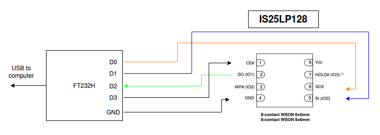
- FT232H interface or equivalent recognized by flashrom, for example: UM232H-B-NC
- 5x Test clips or here
- Soldering station for SMD components.
- Small diameter wire (I used KYNAR WRAPPING WIRE AWG 30).
- Linux computer with flashrom v1.2 installed -> precompiled GNU Linux x64 bin here.
- Recommended: multimeter.
- Recommended: Clamp / tool to keep the BMS push button pressed.
- Optional: USB extender for the FT232H.
- Optional: TC2030-IDC connector, use it to reduce the number of wires to solder from 6 to 4.
Follow this video: https://www.youtube.com/watch?v=XqM4JGT5Mbk
In my case the cells were well balanced:
| Cell # | voltage |
|---|---|
| 1 | 3.477 |
| 2 | 3.481 |
| 3 | 3.445 |
| 4 | 3.477 |
| 5 | 3.482 |
| 6 | 3.481 |
| 7 | 3.480 |
| 8 | 3.480 |
| 9 | 3.481 |
| 10 | 3.480 |
| 11 | 3.480 |
| 12 | 3.480 |
| 13 | 3.480 |
If you have more than 100 [mV] of difference between the cells, then you should try to manually balance the pack by individually charging the concerned cells.
Note 1: You could also read the min and max voltages using a CAN interface, see this article: https://beambreak.org/articles/xr_health_check/
Note 2: If you have more than 500 [mV] of difference it will throw the RLOD again straight away, thanks Venutech for the feedback!
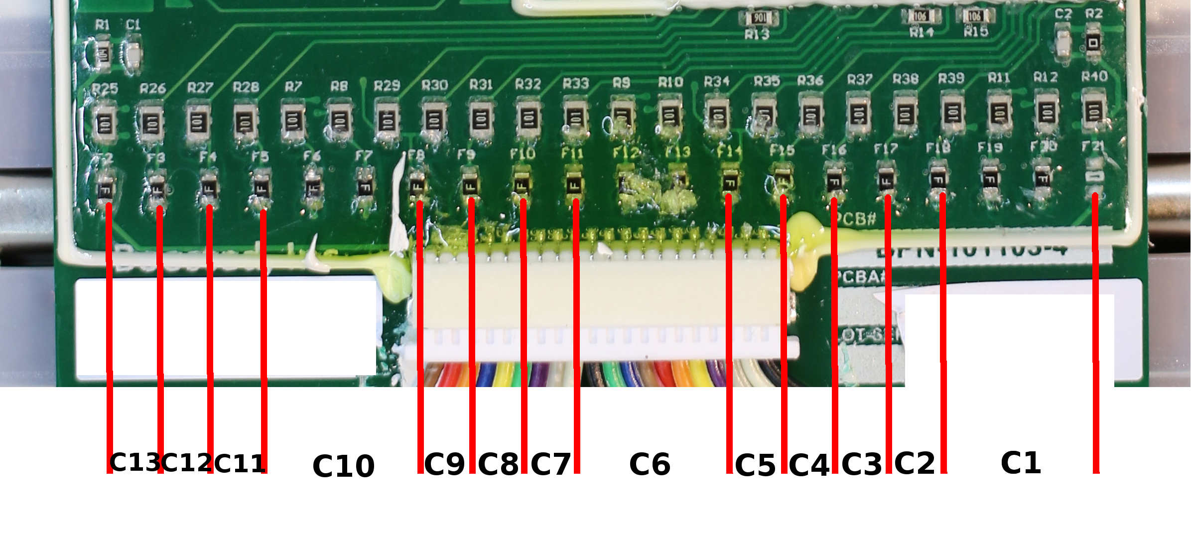
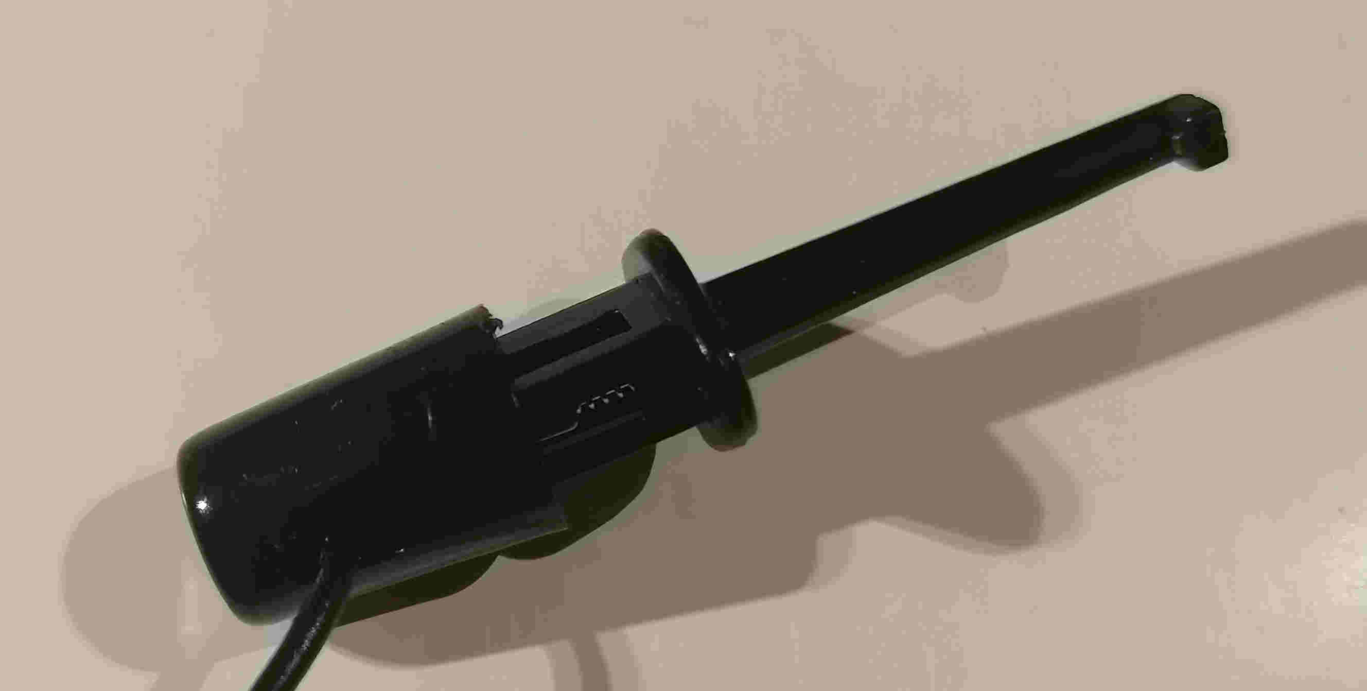
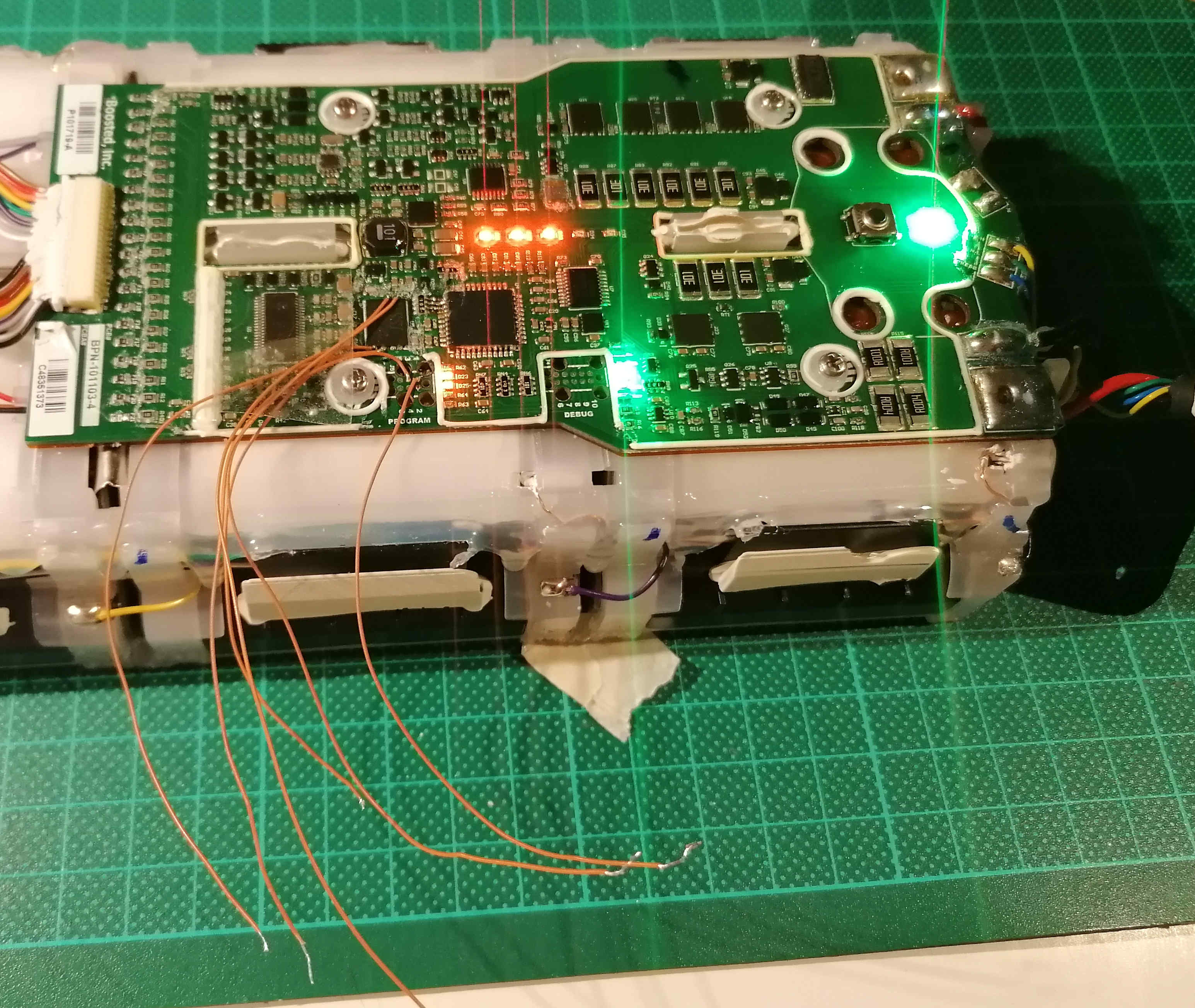
To be more effective in the process, I suggest you to equip the pins D0 to D3 and GND with this type of probe, it will allow to easily connect it to the flash memory (see next step). Alternatively you can also use a breadboard.
- Connect the FT232H to your computer.
- In the Linux terminal launch: flashrom -p ft2232_spi:type=232H
If your FT232H is properly recognized by flashrom, you should see:
flashrom v1.2 on Linux 4.10.0-38-generic (x86_64)
flashrom is free software, get the source code at https://flashrom.org
Using clock_gettime for delay loops (clk_id: 1, resolution: 1ns).
No EEPROM/flash device found.
Note: flashrom can never write if the flash chip isn't found automatically.
In the case your the FT232H is not recognized, run the following commands and go to step 2.
sudo rmmod ftdi_sio
sudo rmmod usbserial
- Once properly recognized by flashrom, keep the FT232H connected to the USB port.
This is very important because flashrom sets the electrical mode of the GPIOs.
Thus, it is safer to do it before attempting a connection to the SPI flash as no current will be accidentally injected!
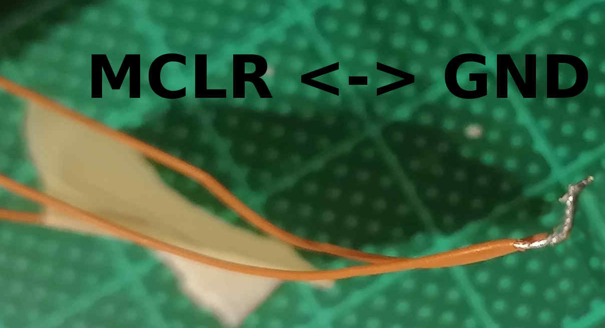
- For this you need to connect MCLR to GND.
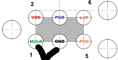
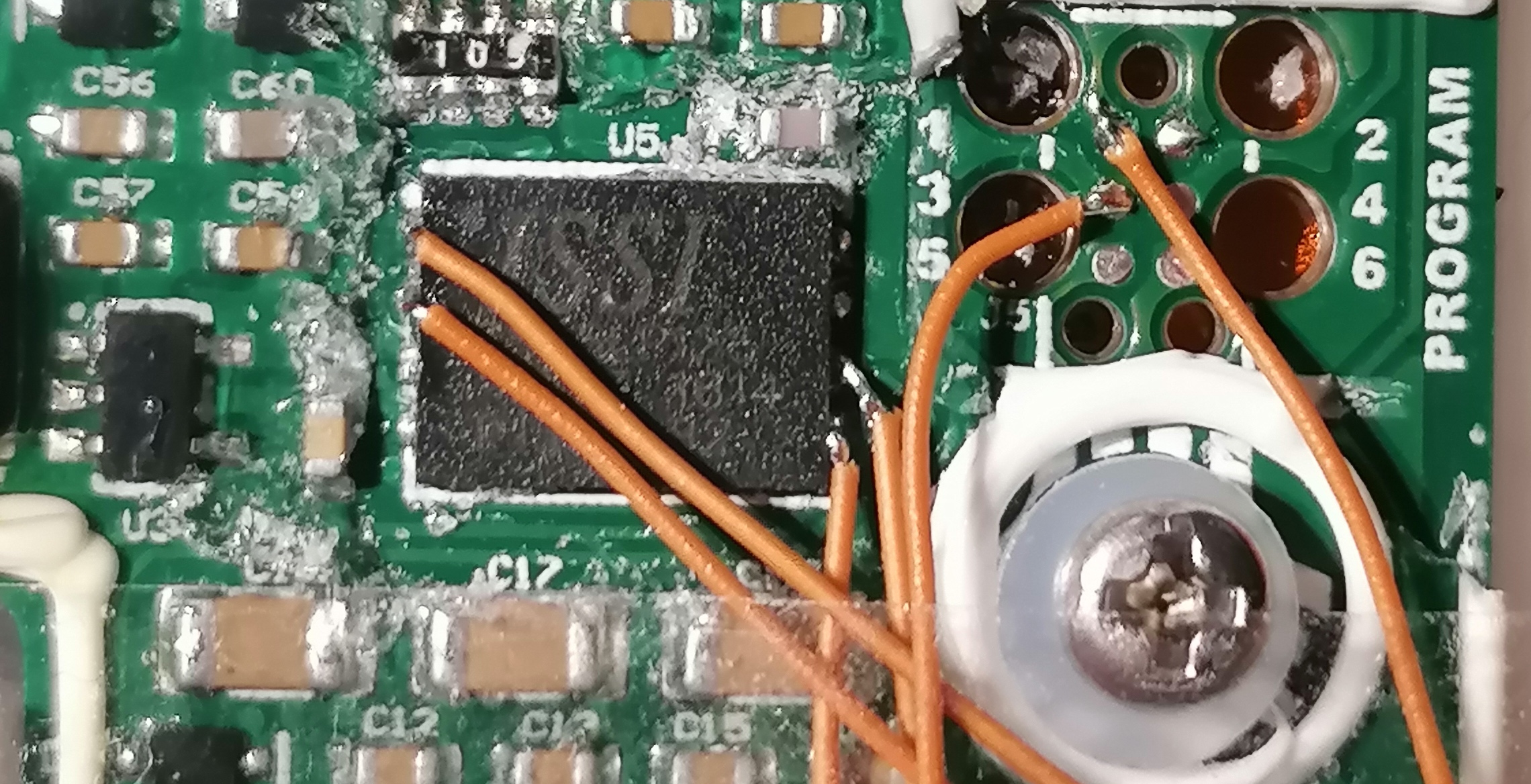
- Solder two wires on pins 1 and 3 or connect the TC2030-IDC cable.
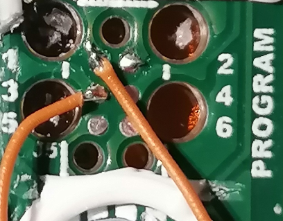

- Connect the other ends to each other.
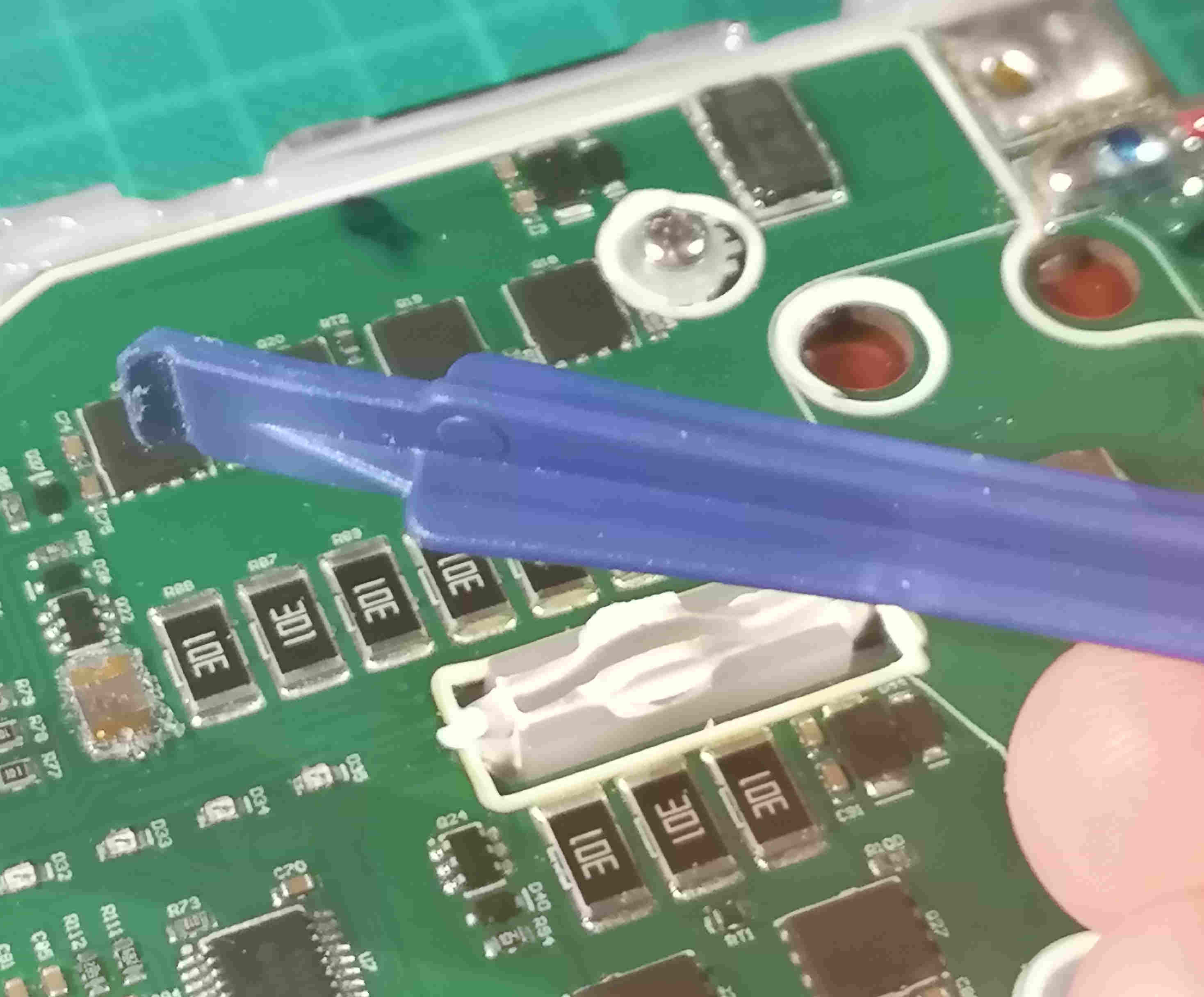
- Use plastic tools, example:
WARNING: make sure the FT232H gpios were properly configured by the command flashrom -p ft2232_spi:type=232H
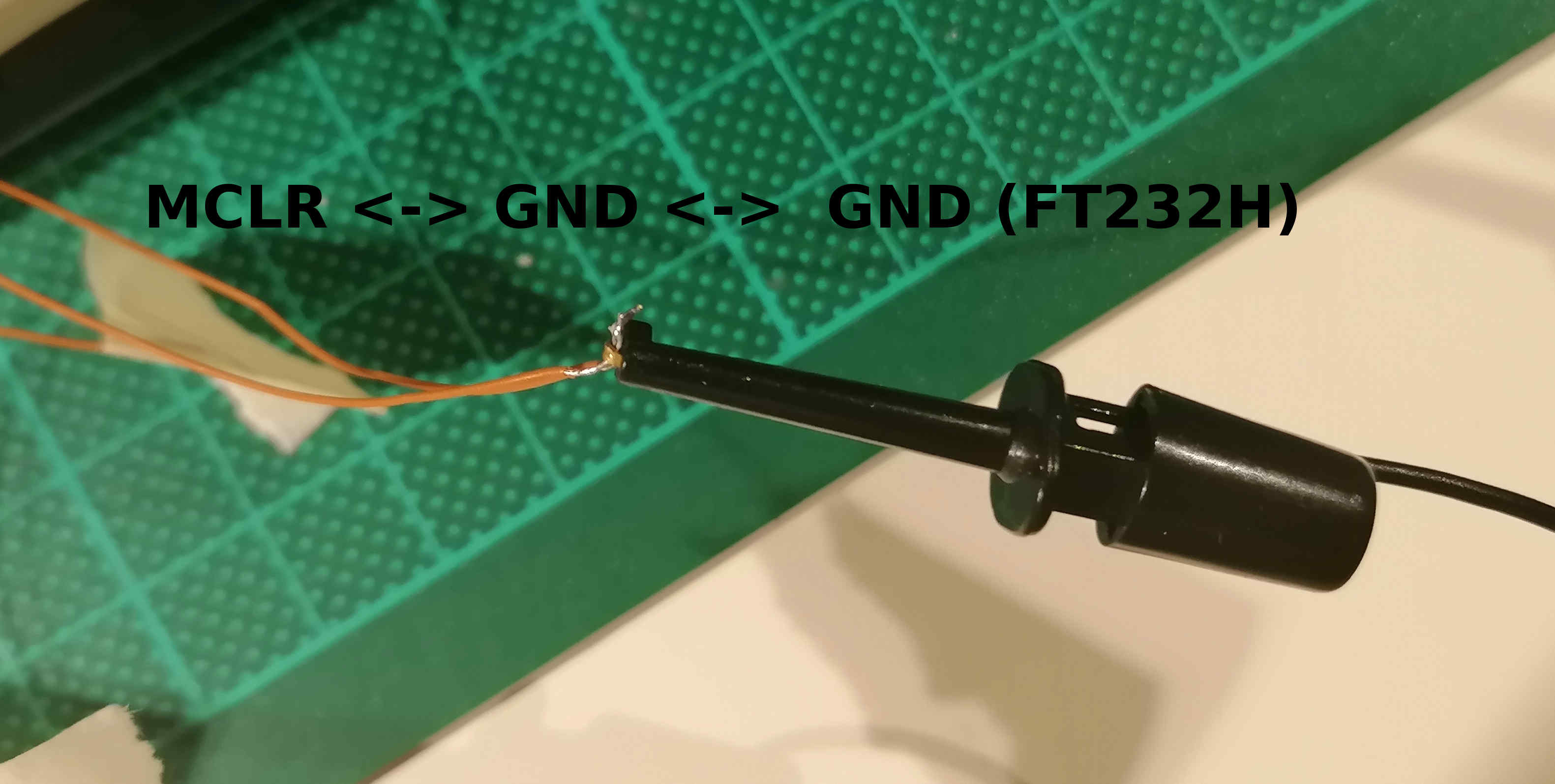
- Connect the FT232H to the SPI wires, start with the GND, you can use the one already bound to MCLR!
For this step, you will need your Linux terminal and your finger to keep pressing the push button of the battery during the flashing operations. (As the MCU is disabled the logic power rail is not held by the FW anymore).
Have a look at the FAQ before doing this.
-
Keep pressing the push button of the battery.
-
flashrom -p ft2232_spi:type=232H -r ./dumpflash.bin
flashrom v1.2 on Linux 4.10.0-38-generic (x86_64)
flashrom is free software, get the source code at https://flashrom.orgUsing clock_gettime for delay loops (clk_id: 1, resolution: 1ns).
Found ISSI flash chip "IS25LP128" (16384 kB, SPI) on ft2232_spi.
Reading flash... done.
-
Release the push button
-
Keep pressing the push button
-
flashrom -p ft2232_spi:type=232H -v ./dumpflash.bin
flashrom v1.2 on Linux 4.10.0-38-generic (x86_64)
flashrom is free software, get the source code at https://flashrom.org
Using clock_gettime for delay loops (clk_id: 1, resolution: 1ns).
Found ISSI flash chip "IS25LP128" (16384 kB, SPI) on ft2232_spi.
Verifying flash... VERIFIED.
Note: Make sure the verification is "VERIFIED", otherwise try again to dump and verify.
-
Release the push button
-
Keep pressing the push button (for a long time -> use a clamp)
-
flashrom -p ft2232_spi:type=232H -E
flashrom v1.2 on Linux 4.10.0-38-generic (x86_64)
flashrom is free software, get the source code at https://flashrom.orgUsing clock_gettime for delay loops (clk_id: 1, resolution: 1ns).
Found ISSI flash chip "IS25LP128" (16384 kB, SPI) on ft2232_spi.
Erasing and writing flash chip...
-
Wait for up to 10 minutes for the operation to complete (use this opportunity to reflect about life stuff).
-
Press ctrl-c to exit this never ending operation (if it still didn't finish)
-
flashrom -p ft2232_spi:type=232H
-
Release the push button and relax :)
- Disconnect the FT232H from the SPI CHIP (last wire to be removed is GND)
- Disconnect MCLR from GND
I did charge the battery until I got the green light. The measured cell voltage when fully charged is ~3.900 [V].
If you have any questions you can find me on the boosted board discord or at: pro(at)jonataubert.com
Q: How does it work?
A: The current theory (which may be inaccurate and wrong) is that when the cells are heavily unbalanced (>500 mV), an error is triggered. As a result, the error and debug data are written to the SPI FLASH. If these information are present, the board stays locked RLOD. Boosted service and support center would then extract and analyze what happened. Thus, clearing this memory removes the RLOD.
Q: Where else can I find reverse engineering information about BB?
A: beambreak.org and Lambert, please let me know if you have other links!
Q: Does it work with any firmware?
A: v2.5.1 / v2.1.7 / I don't know yet about others, please let me know and I will update the list.
Q: Does it work with SR batteries?
A: I don't know yet, please inform me if it does the job!
Q: I don't want to solder anything on the B2XR, how can I do it?
A: You may be able to achieve it by designing a test jig with needles/pogo pins. if you use needles you may eventually not need to remove the conformal coating anymore!
Q: Can I do it with macOS or Windows or a Raspberry Pi
A1: flashrom can be installed on macOS using brew, it should work! If it doesn't you can always compile it from the sources.
A2: https://flashrom.org/Windows or maybe using another SPI flash / Windows based software...
A3: Yes, from what I could see flashrom uses its integrated SPI lines (header) so you wouldn't even need the FT232H!
Q: What should I do with the dumpflash.bin file?
A: This is the backup of the data that were stored in the flash before the erasing process. Keep it!
Q: Ok, so we erased the content of the flash but would removing the SPI flash do the same?
A: Nope, if you do so you will end up with a different RLOD error code.
Q: What happens if I write back the backup bin data to the flash?
A: The RLOD comes back, isn't it nice ;P
Q: Does this method work if the cells are unbalanced by more than 500 [mV]?
A: No, you must have your cells balanced before the flash procedure.
Q: I accidentally released the push button while erasing the FLASH and got such messages:
Found ISSI flash chip "IS25LP128" (16384 kB, SPI) on ft2232_spi.
Erasing and writing flash chip... FAILED at 0x00069000! Expected=0xff, Found=0x00, failed byte count from 0x00069000-0x00069fff: 0x1000 ERASE FAILED!
Looking for another erase function.
FAILED at 0x00069000! Expected=0xff, Found=0x00, failed byte count from 0x00069000-0x00069fff: 0x1000
ERASE FAILED!
No usable erase functions left.
FAILED!
Your flash chip is in an unknown state.
A: run flashrom -p ft2232_spi:type=232H to reset the GPIOs, then you can restart the erasing process, if you still get this message, go ahead it may have properly erased the chip anyway (at least it works with me).