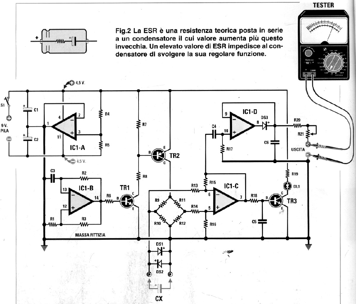
The schematic of this meter was published in an Italian magazine Nuova Elettronica No. 212.
The schematic of this meter was published in an Italian magazine Nuova Elettronica No. 212. I found it more than five years ago on Talino Tribuzio's IZ7ATH site when I was looking for a simple ESR meter circuit.
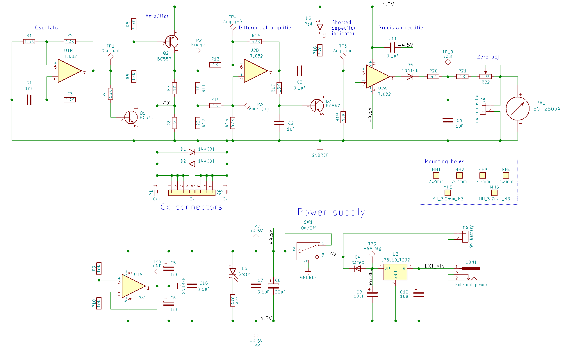
R1 = 1.5K
R2,R3,R4,R5 = 10K
R6 = 68K
R7 = 4.7K
R8 = 12K
R9,R11 = 1K 1%
R10,R12 = 22 1%
R13,R14 = 1K
R15,R16,R17 = 47K
R18 = 15K
R19 = 680
R20 = 2.2K
R21 = 20K TRIMMER

C1,C2 = 1uF electrolytic
C3 = 1nF POLY
C4 = 100nFF POLY
C5,C6 = 1uF POLY
DS1, DS2 = 1N4007
DS3 = 1N4148
TR1,TR3 = BC547
TR2 = BC557
IC1 = TL084
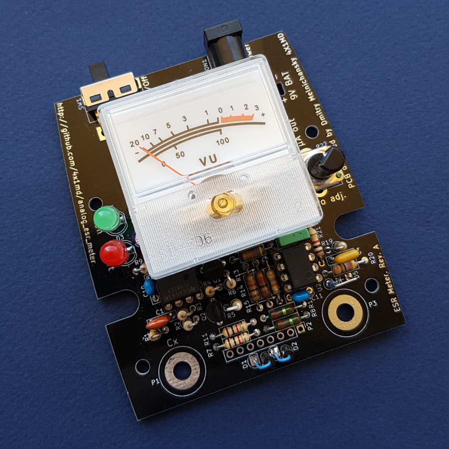
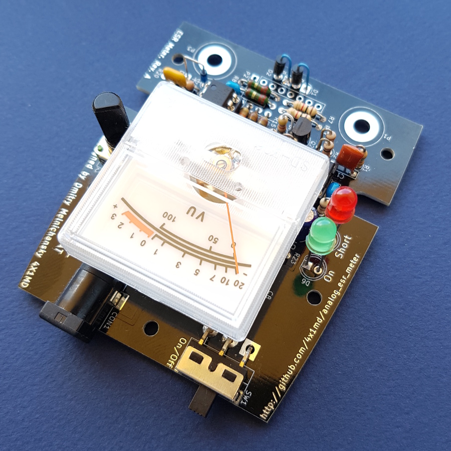
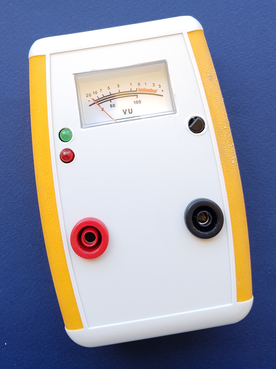
- Fitting the circuit in an enclosure box.
- Dual power supply battery and external.
A ready available 118x78x33mm plastic box which was purchased on AliExpress. The box is made of a good quality plastic, has enough space for the PCB and a battery compartment.
- http://fillwithgoodthings.blogspot.com/2013/05/esr-meter-schematic.html
- http://kripton2035.free.fr/analog%20esr/esr-poptronix.html
- http://electronics-diy.com/electronic_schematic.php?id=950
- http://www.geocities.jp/shoranosekai/ESR_Tester_Schematic.jpg
- http://ludens.cl/Electron/esr/esr.html
- http://electronics-diy.com/electronic_schematic.php?id=949
If you like this project, or found here some useful information and want to say thanks, or encourage me to do more, you can buy me a coffee!


You can aslo make a donation with PayPal:

73 de 4X1MD