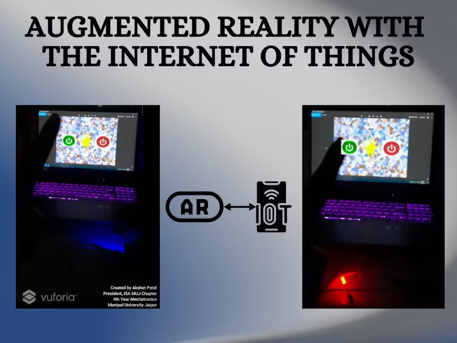
Control AC Appliances using Augmented Reality Buttons over the Internet from anywhere in the world.
Click on the image preview to watch the video demonstration of the project.

- NodeMCU (ESP8266) MCU
- LED
- Jumper Wires
- Unity 3D
- Vuforia Engine
- Microsoft Visual Studio Code
- Arduino IDE
- Blynk App
This is a demonstration of Augment Reality (AR) with the Internet of Things (IoT). The AC appliance can be controlled over the internet from anywhere in the world via virtual buttons in Augmented Reality. In this demonstration, I have used an LED but a relay module can be used in place of the LED to control any AC appliance. As soon as the camera recognises the target image, two virtual buttons 'ON' and 'OFF' appear in augmented reality. The appliance or the LED in this case can be controlled by clicking those buttons in real-time in space in the air.
- Basic knowledge of Unity 3D
- Basic knowledge of programming
- Basic knowledge of Arduino IDE
- Basic knowledge of Vuforia Engine
- Basic knowledge of Blynk App
- Select your Operating System properly and install the latest version of Arduino IDE. https://www.arduino.cc/en/software
- Install the current Arduino IDE at the 1.8.15 level or later. The current version is on the Arduino website.
- Start Arduino and open the Preferences window.
- Enter https://arduino.esp8266.com/stable/package_esp8266com_index.json into the File>Preferences>Additional Boards Manager URLs field of the Arduino IDE. You can add multiple URLs, separating them with commas.
- In the Arduino IDE Go to Tools -> Board (…) -> Boards manager…
- Search for “ESP8266”, click the suggested result and press install.
- Install the new board manager for the ESP8266 chip
- Confirm the installation and choose the NodeMCU board for the current board
- Go to Tools -> Board (…) and select “NodeMCU 1.0 (ESP 12-E module)” from the list.
- Download the Blynk App from the Play Store or App Store.
- Create a new account or login if you already have one.
- Create a new project and name it.
- Select the device as NodeMCU and connection type as Wi-Fi.
- An authentication token will be sent to your registered email address.
- Click on the ‘+’ icon again and add a button.
- Click on it and set the name of your choice, set the pin to Virtual-V1, toggle set to ‘push’, and rest of the setting as per your choice.
- Click the play button at the right top of the application and the configuration is completed.
- Open the Arduino IDE and go to File -> Preferences.
- In the Additional Boards Manager URLs field, enter https://arduino.esp8266.com/stable/package_esp8266com_index.json.
- Go to Tools -> Board -> Boards Manager.
- Search for ESP8266 and install the latest version.
- Go to Tools -> Board and select NodeMCU 1.0 (ESP-12E Module).
- Go to Tools -> Port and select the port to which the NodeMCU is connected.
- Copy the code from the file 'ar_with_iot_ino.ino’ and paste it in the Arduino IDE.
- Replace the ‘your_authentication_token’ with the authentication token that was sent to your registered email address.
- Replace the ‘wifi_name’ with the name of your Wi-Fi network.
- Replace the ‘wifi_password’ with the password of your Wi-Fi network.
- Click on the upload button and the code will be uploaded to the NodeMCU.
#define BLYNK_PRINT Serial
#define relay D0 //setting the digital pin as D0
#include <ESP8266WiFi.h>
#include <WiFiClient.h>
#include <BlynkSimpleEsp8266.h>
char auth[] = "your_authentication_token";
char ssid[] = "wifi_name";
char pass[] = "wifi_password";        //leave blank in case of an open network.
BLYNK_WRITE(V1) //enter the virtual pin that was selected by you previously
{

  int pinValue = param.asInt(); // assigning incoming value from pin V1 to a variable
  digitalWrite(relay,pinValue);

    if(pinValue==1)
  {
    Serial.println("ON");
  }

  if(pinValue==0)
  {
    Serial.println("OFF");
  }

}
void setup()
{
  Serial.begin(9600);
  Blynk.begin(auth, ssid, pass);
  pinMode(relay, OUTPUT);
}
void loop()
{
  Blynk.run();
}-
Open Unity Hub.
-
Click on New and Name the project.
-
Add vuforia engine package inside the Unity3D engine to enable unity3D with the AR camera.
-
Go to developer.vuforia.com and create and login into your account. (Example: using Gmail ID)
-
Click and download the file:
-
Click and open the file and click Import to import all vuforia packages. Click ‘update’ if prompted.
-
Delete the main camera from the panel.
-
Right-click>vuforia engine>AR Camera
-
For Target Image:
-
Go to the developer.vuforia.com same website and click on Develop.
-
Click on Target Manager> Add database.
-
Name it as per your choice and select ‘Device’.
-
Click on the name> Add Target Image> Browse the target image in your system> choose. Width = 1. Name as per your choice.
-
Download this database by selecting the database and download for Unity Editor and click on download.
-
Open the file to directly import it into your unity project.
-
-
To add licence:
- Click on AR Camera and then on the right-hand side find the ‘open vuforia configuration’ and add the licence.
-
To generate licence key:
-
Go to the developer.vuforia.com same website and click on Develop.
-
Click on licence manager and click on get development key. Give it a name and click confirm.
-
Open the licence and copy the entire licence key and paste it in unity editor.
-
-
Right-click on AR Camera> vuforia engine> image target
-
On the right-hand side, under ‘image target behaviour’, select type as ‘from database’ select the name of the database and name of the image target.
-
Click on image target, go to advanced under ‘image target behaviour’ click on add virtual button.
-
Add one more virtual button by repeating step 10.
-
Rearrange the buttons, one on left and one on the right side of the image target.
-
Rename the virtual buttons as ‘ON’ and ‘OFF’.
-
Right-click on ON and under 3D object click on ‘Plane’.
-
Resize the plane to match the size of the virtual button.
-
Repeat steps 18 and 19 for the OFF button.
-
Add images of ON and OFF in the unity project.
-
Drag and drop the ‘on image’ on the ON button.
-
Drag and drop the ‘off image’ on the OFF button.
-
Change the orientation by changing the Y-axis to 180.
-
Add the C# file in the unity project.
-
Drag and drop the script on the ‘Image target’.
-
Click on Image Target and provide all the data under the ‘Script’ panel.
-
Add the virtual buttons as well as the URLs.
-
Test the application by clicking the play button in the unity editor.
using System.Collections;
using System.Collections.Generic;
using UnityEngine;
using Vuforia;
using UnityEngine.Networking;
public class ARwithIoT_Script : MonoBehaviour
{
public VirtualButtonBehaviour VB_ON;
public VirtualButtonBehaviour VB_OFF;
public string URL_ON;
public string URL_OFF;
IEnumerator GetRequest(string uri)
{
using (UnityWebRequest webRequest = UnityWebRequest.Get(uri))
{
// Request and wait for the desired page.
yield return webRequest.SendWebRequest();
}
}
void Start()
{
VB_ON.RegisterOnButtonPressed(OnButtonPressed_on);
VB_OFF.RegisterOnButtonPressed(OnButtonPressed_off);
}
public void OnButtonPressed_on(VirtualButtonBehaviour VB_ON)
{
StartCoroutine(GetRequest(URL_ON));
Debug.Log("LED IS ON");
}
public void OnButtonPressed_off(VirtualButtonBehaviour VB_OFF)
{
StartCoroutine(GetRequest(URL_OFF));
Debug.Log("LED IS OFF");
}
}The schematic diagram of the project can be found in the file 'img2.jpg'.