The end goal is to setup an L3VPN between two sites, each site actually being a K8S worker node.
The environment used to build this is described here
For this first iteration, we will setup BGP between two routers - each router can be seen as a CE; the topology won't have PE and P for now.
The infrastructure used will be one server, in which there is two worker nodes of an OpenShift 4.8 cluster. The workers are deployed using libvirt and using virtual networks.
For the current lab, we will build two customer sites, each one fronted by a router. The goal will be to have BGP advertising the other site's routes, so client in site 1 can reach client in site 2.
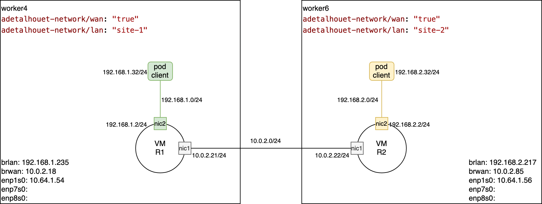
See here the high-level design showing the two sites along with clients for the respective sites.
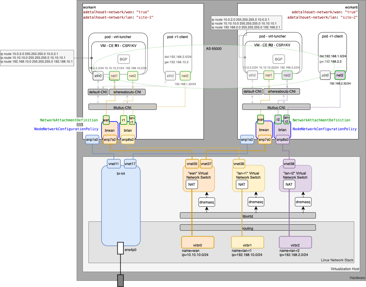
Below is the low-level design showing all the network interaction within the server, up to the VM and POD within OpenShift.
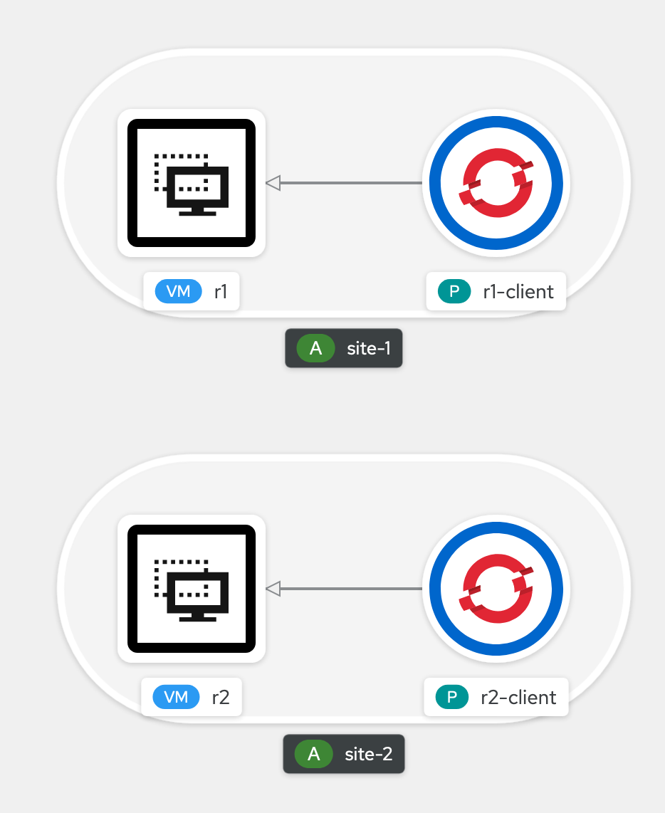
Finally, from an OpenShift standpoint, using the developer view, this is what you could observed.
The first thing we will do is add two labels on the workers we will use:
adetalhouet-network/wan: "true"will be used to denote the node belongs to our networkadetalhouet-network/lan: "site-1"will be used to denote a specific site (and ultimatly help with placement)
In my cluster, I will use worker4 and worker6.
For worker4, I have the following
╰─○ oc get node worker4.hetzner.sandbox1091.opentlc.com --show-labels
NAME                                      STATUS   ROLES    AGE   VERSION           LABELS
worker4.hetzner.sandbox1091.opentlc.com   Ready    worker   24d   v1.21.1+a620f50   adetalhouet-network/lan=site-1,adetalhouet-network/wan=true,[...]
For worker6, I have the followin
╰─○ oc get node worker6.hetzner.sandbox1091.opentlc.com --show-labels
NAME                                      STATUS   ROLES    AGE   VERSION           LABELS
worker6.hetzner.sandbox1091.opentlc.com   Ready    worker   16d   v1.21.1+a620f50   adetalhouet-network/lan=site-2,adetalhouet-network/wan=true,[...]
Define and start the virtual network we will use for the WAN and the respective sites' LAN connectivity.
virsh net-define libvirt/wan.xml
virsh net-define libvirt/lan-r1.xml
virsh net-define libvirt/lan-r2.xml

virsh net-start wan
virsh net-start lan-r1
virsh net-start lan-r2

virsh net-autostart wan
virsh net-autostart lan-r1
virsh net-autostart lan-r2
Add the WAN and LAN interfaces to each site, respecing the LAN attribution per site.
For Site 1 (worker4)
virsh attach-interface --domain worker4 --type network --source wan --model virtio --config --live
virsh attach-interface --domain worker4 --type network --source lan-r1 --model virtio --config --live
For Site 2 (worker6)
virsh attach-interface --domain worker6 --type network --source wan --model virtio --config --live
virsh attach-interface --domain worker6 --type network --source lan-r2 --model virtio --config --live
In both cases, the WAN port will be enp7s0 and the LAN port will be enp8s0.
To detach the interface, the following command can be used
virsh detach-interface --domain worker6 --type network --mac 52:54:00:0b:8a:17
On each host, will need to create a bridge interface for the LAN and the WAN, in order to leverage Mutlus CNI sub-plugin to control network attachement.
To configure network interfaces, we will use the node labels, for placement, and the NodeNetworkConfigurationPolicy CR from NMState.
Review and apply the network interfaces
# Create the WAN interface on both nodes
oc apply -f network/interfaces/brwan.yaml
# Create the LAN interface for Site 1
oc apply -f network/interfaces/brlan-r1.yaml
# Create the LAN interface for Site 2
oc apply -f network/interfaces/brlan-r2.yaml
Review the created objects, along with their status. Note: it will take few seconds before it is shown as properly configured. See the step right after to have more details about the application of the interface in the nodes.
╰─○ oc get nncp
NAME       STATUS
brlan-r1   SuccessfullyConfigured
brlan-r2   SuccessfullyConfigured
brwan      SuccessfullyConfigured
When creating the above NodeNetworkConfigurationPolicy, the NMState operator will generate NodeNetworkConfigurationEnactment. The enactment is responsible for creating the linux bridge. You can review the placement / status of the enactement using the following command.
╰─○ oc get nnce
NAME                                               STATUS
master1.hetzner.sandbox1091.opentlc.com.brlan-r1   NodeSelectorNotMatching
master1.hetzner.sandbox1091.opentlc.com.brlan-r2   NodeSelectorNotMatching
master1.hetzner.sandbox1091.opentlc.com.brwan      NodeSelectorNotMatching
master2.hetzner.sandbox1091.opentlc.com.brlan-r1   NodeSelectorNotMatching
master2.hetzner.sandbox1091.opentlc.com.brlan-r2   NodeSelectorNotMatching
master2.hetzner.sandbox1091.opentlc.com.brwan      NodeSelectorNotMatching
master3.hetzner.sandbox1091.opentlc.com.brlan-r1   NodeSelectorNotMatching
master3.hetzner.sandbox1091.opentlc.com.brlan-r2   NodeSelectorNotMatching
master3.hetzner.sandbox1091.opentlc.com.brwan      NodeSelectorNotMatching
worker1.hetzner.sandbox1091.opentlc.com.brlan-r1   NodeSelectorNotMatching
worker1.hetzner.sandbox1091.opentlc.com.brlan-r2   NodeSelectorNotMatching
worker1.hetzner.sandbox1091.opentlc.com.brwan      NodeSelectorNotMatching
worker2.hetzner.sandbox1091.opentlc.com.brlan-r1   NodeSelectorNotMatching
worker2.hetzner.sandbox1091.opentlc.com.brlan-r2   NodeSelectorNotMatching
worker2.hetzner.sandbox1091.opentlc.com.brwan      NodeSelectorNotMatching
worker3.hetzner.sandbox1091.opentlc.com.brlan-r1   NodeSelectorNotMatching
worker3.hetzner.sandbox1091.opentlc.com.brlan-r2   NodeSelectorNotMatching
worker3.hetzner.sandbox1091.opentlc.com.brwan      NodeSelectorNotMatching
worker4.hetzner.sandbox1091.opentlc.com.brlan-r1   SuccessfullyConfigured
worker4.hetzner.sandbox1091.opentlc.com.brlan-r2   NodeSelectorNotMatching
worker4.hetzner.sandbox1091.opentlc.com.brwan      SuccessfullyConfigured
worker5.hetzner.sandbox1091.opentlc.com.brlan-r1   NodeSelectorNotMatching
worker5.hetzner.sandbox1091.opentlc.com.brlan-r2   NodeSelectorNotMatching
worker5.hetzner.sandbox1091.opentlc.com.brwan      NodeSelectorNotMatching
worker6.hetzner.sandbox1091.opentlc.com.brlan-r1   NodeSelectorNotMatching
worker6.hetzner.sandbox1091.opentlc.com.brlan-r2   SuccessfullyConfigured
worker6.hetzner.sandbox1091.opentlc.com.brwan      SuccessfullyConfigured
As I used labels to target the specific nodes, you can see worker4 and worker6 are configured with the WAN interface and their respective LAN interface. All the other nodes are left intact.
Now the bridge interface are ready, we can create the network attachement that will be used to create VMs and PODs. We have a total of 5 network attachement to create, as follow:
- one for the WAN connectivity - it will be used only by the routers (wan.yaml)
- one per router configured without DHCP - i.e. no IPAM (r1.yaml, r2.yaml)
- one per LAN site configured with DHCP and additional routes - this is to inject a static route enabling traffic to go through the WAN in order to reach the other site. (lan-r1.yaml, lan-r2.yaml)
Let's apply them
oc create -f network/attachements/lan-r1.yaml
oc create -f network/attachements/lan-r2.yaml
oc create -f network/attachements/r1.yaml
oc create -f network/attachements/r2.yaml
oc create -f network/attachements/wan.yaml
The router will be Cisco CSR1000V. So we will create a DataVolume hosting the cd-rom (qcow2). That DataVolume will be used to boot the routers.
oc create -f routers/disk/csr1kv.yaml
CSR1KV router support day0 configuration, which means we can create the router's configuration in advance, and have it applied at the first boot.
Respectively, for Site 1 and Site 2, I have built the configuration and put it within the respective routers folders.
It is mandatory the configuration file is called iosxe_config.txt.
Let's review the day0 configuration of both routers:
- set a hostname
- statically define the LAN and WAN interfaces
- statically define routes for LAN and WAN network
- define BGP router ID, setup BGP session with peered router, redistribute static routes
Once we are satified with the configuration, we need to create an .iso disk and load the it into a DataVolume. That will then be used within the VM at start time.
mkisofs -l -o r1/r1_config.iso r1/iosxe_config.txt
virtctl image-upload dv r1-config --access-mode ReadWriteMany --block-volume --storage-class=ocs-storagecluster-ceph-rbd --size=500Mi --image-path=./r1/r1_config.iso

mkisofs -l -o r2/r2_config.iso r2/iosxe_config.txt
virtctl image-upload dv r2-config --access-mode ReadWriteMany --block-volume --storage-class=ocs-storagecluster-ceph-rbd --size=500Mi --image-path=./r2/r2_config.iso
Review all the DataVolume before going to next step, and ensure they have all succeeded.
╰─○ oc get dv
NAME           PHASE       PROGRESS   RESTARTS   AGE
csr1kv-qcow2   Succeeded   100.0%                4d18h
r1-config      Succeeded   N/A                   19h
r1-rootdisk    Succeeded                         19h
r2-config      Succeeded   N/A                   19h
r2-rootdisk    Succeeded                         19h
Now, let's create the routers, that actually are VMs. The respective router definition can be find in the routers folder.
Each router is define as follow:
- boot disk is a copy of the DataVolume created before that holds the CSR1KV qcow2 image
- config cd-rom that points to the configuration build at the previous step
- two interfaces, one for the WAN and on for the LAN it is serving.
- 4vCPU / 8GB RAM (although it could be easily by twice less)
It will take some time for the routers to come up, as I'm using nested virtualization (~8mn). To see what is happening in the routers, use the following commands.
virtctl console r1
virtctl console r2
Once the routers are fully up, review the interfaces are configured properly:
r1>sh proto
Global values:
  Internet Protocol routing is enabled
GigabitEthernet1 is up, line protocol is up
  Internet address is 10.0.2.21/24
GigabitEthernet2 is up, line protocol is up
  Internet address is 192.168.1.2/24
and validate BGP is all set:
r1>sh ip route
Codes: L - local, C - connected, S - static, R - RIP, M - mobile, B - BGP
       D - EIGRP, EX - EIGRP external, O - OSPF, IA - OSPF inter area
       N1 - OSPF NSSA external type 1, N2 - OSPF NSSA external type 2
       E1 - OSPF external type 1, E2 - OSPF external type 2
       i - IS-IS, su - IS-IS summary, L1 - IS-IS level-1, L2 - IS-IS level-2
       ia - IS-IS inter area, * - candidate default, U - per-user static route
       o - ODR, P - periodic downloaded static route, H - NHRP, l - LISP
       a - application route
       + - replicated route, % - next hop override, p - overrides from PfR

Gateway of last resort is not set

      10.0.0.0/8 is variably subnetted, 2 subnets, 2 masks
C        10.0.2.0/24 is directly connected, GigabitEthernet1
L        10.0.2.21/32 is directly connected, GigabitEthernet1
      192.168.1.0/24 is variably subnetted, 2 subnets, 2 masks
C        192.168.1.0/24 is directly connected, GigabitEthernet2
L        192.168.1.2/32 is directly connected, GigabitEthernet2
B     192.168.2.0/24 [200/0] via 10.0.2.22, 17:48:52
You can see the last route (prefixed with B) has been advertised by BGP and enables traffic to go through the WAN network.
Now that the routers and BGP are ready, we can create the clients within each site, and attempt a ping test to validate traffic is going through the WAN.
The client pod manifests are located in the clients folder. We are using node selector to ensure the client for site 1 gets deployed in site 1, and same for site 2.
oc create -f clients/r1-client.yaml
oc create -f clients/r2-client.yaml
Validate the pods are correctly created
╰─○ oc get pods
NAME                     READY   STATUS    RESTARTS   AGE
r1-client                1/1     Running   0          19h
r2-client                1/1     Running   0          18h
virt-launcher-r1-zhgkm   1/1     Running   0          20h
virt-launcher-r2-m8m29   1/1     Running   0          20h
Validate they were properly assign an IP address in the LAN they belong to. To do this, either do
╰─○ oc describe pod r1-client
Name:         r1-client
Namespace:    default
Priority:     0
Node:         worker4.hetzner.sandbox1091.opentlc.com/10.64.1.54
Start Time:   Sun, 24 Oct 2021 21:46:44 -0400
Labels:       app.kubernetes.io/part-of=site-1
Annotations:  app.openshift.io/connects-to: [{"apiVersion":"kubevirt.io/v1","kind":"VirtualMachine","name":"r1"}]
              k8s.v1.cni.cncf.io/network-status:
                [{
                    "name": "openshift-sdn",
                    "interface": "eth0",
                    "ips": [
                        "10.129.3.225"
                    ],
                    "default": true,
                    "dns": {}
                },{
                    "name": "default/lan-r1",
                    "interface": "net1",
                    "ips": [
                        "192.168.1.32"
                    ],
                    "mac": "d6:93:97:31:0f:dc",
                    "dns": {}
                }]
              k8s.v1.cni.cncf.io/networks: lan-r1
[...]
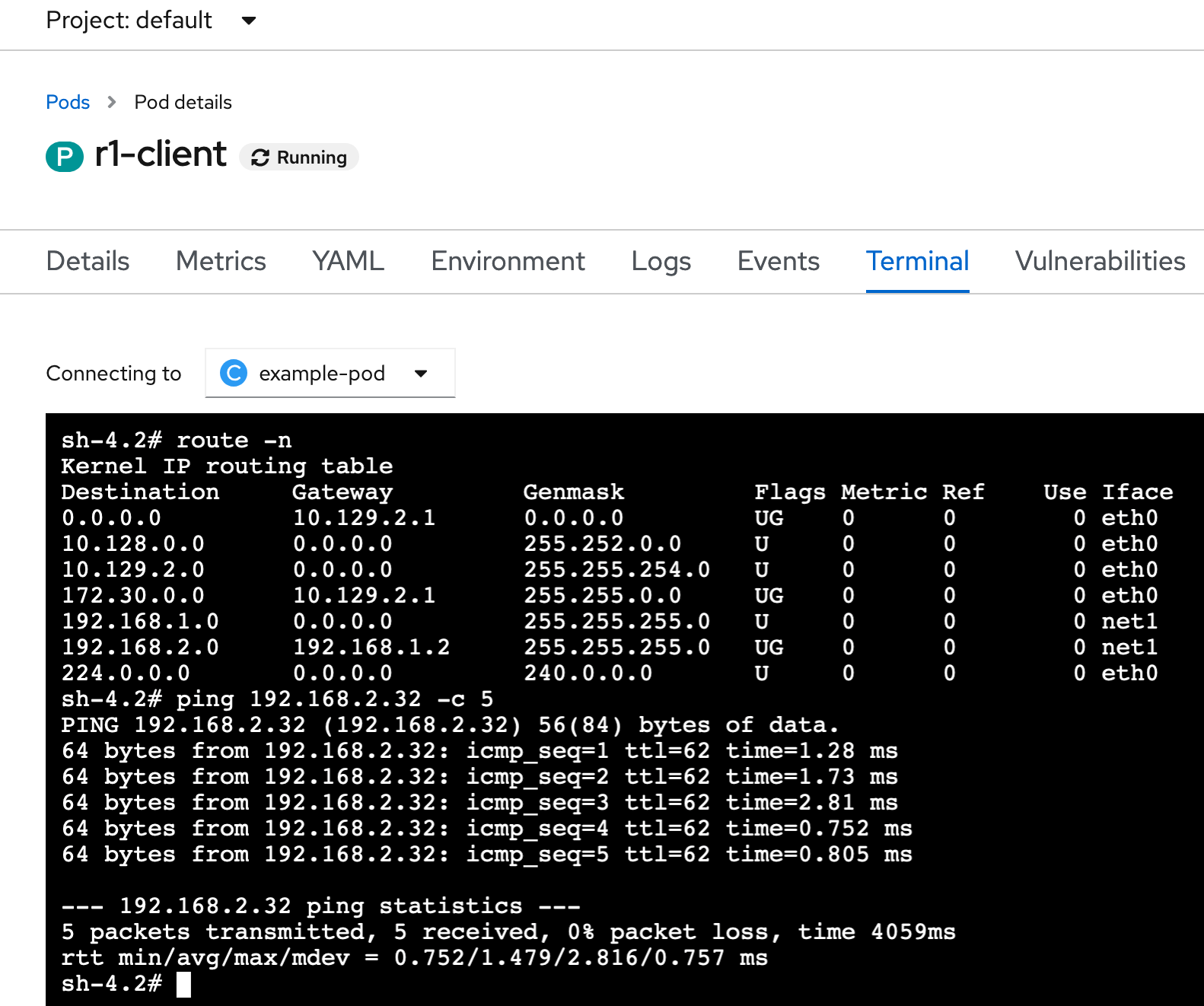
or get into the pod and validate the interface and routing table (example below for Site 1 client)
╰─○ oc exec r1-client -- ip route
default via 10.129.2.1 dev eth0
10.128.0.0/14 dev eth0
10.129.2.0/23 dev eth0 proto kernel scope link src 10.129.3.225
172.30.0.0/16 via 10.129.2.1 dev eth0
192.168.1.0/24 dev net1 proto kernel scope link src 192.168.1.32
192.168.2.0/24 via 192.168.1.2 dev net1
224.0.0.0/4 dev eth0

╰─○ oc exec r1-client -- ip a
1: lo: <LOOPBACK,UP,LOWER_UP> mtu 65536 qdisc noqueue state UNKNOWN group default qlen 1000
    link/loopback 00:00:00:00:00:00 brd 00:00:00:00:00:00
    inet 127.0.0.1/8 scope host lo
       valid_lft forever preferred_lft forever
    inet6 ::1/128 scope host
       valid_lft forever preferred_lft forever
3: eth0@if1635: <BROADCAST,MULTICAST,UP,LOWER_UP> mtu 1450 qdisc noqueue state UP group default
    link/ether 0a:58:0a:81:03:e1 brd ff:ff:ff:ff:ff:ff link-netnsid 0
    inet 10.129.3.225/23 brd 10.129.3.255 scope global eth0
       valid_lft forever preferred_lft forever
    inet6 fe80::4c73:58ff:fe6d:83ea/64 scope link
       valid_lft forever preferred_lft forever
5: net1@if1636: <BROADCAST,MULTICAST,UP,LOWER_UP> mtu 1500 qdisc noqueue state UP group default
    link/ether d6:93:97:31:0f:dc brd ff:ff:ff:ff:ff:ff link-netnsid 0
    inet 192.168.1.32/24 brd 192.168.1.255 scope global net1
       valid_lft forever preferred_lft forever
    inet6 fe80::d493:97ff:fe31:fdc/64 scope link
       valid_lft forever preferred_lft forever
For Site 1, we can see the route toward Site 2 LAN is there, with the gateway being our router interface on Site 1 LAN. And we can see the pod got an ip in the Site 1 LAN as well.
In order to affirm we have a working environment, we will ping the client in Site2 from the client in Site1. If that works, it means the route were properly advertised through BGP, and the overall networking setup is working.
Execute from a ping from Site 1 client to Site 2 client
╰─○ oc exec r1-client -- ping -c 5 192.168.2.32
PING 192.168.2.32 (192.168.2.32) 56(84) bytes of data.
64 bytes from 192.168.2.32: icmp_seq=1 ttl=62 time=1.17 ms
64 bytes from 192.168.2.32: icmp_seq=2 ttl=62 time=0.994 ms
64 bytes from 192.168.2.32: icmp_seq=3 ttl=62 time=1.16 ms
64 bytes from 192.168.2.32: icmp_seq=4 ttl=62 time=1.11 ms
64 bytes from 192.168.2.32: icmp_seq=5 ttl=62 time=1.20 ms

--- 192.168.2.32 ping statistics ---
5 packets transmitted, 5 received, 0% packet loss, time 4004ms
rtt min/avg/max/mdev = 0.994/1.129/1.200/0.075 ms