Lime_Gen3_IoT_Replacement
Note: This project is not endorsed or supported by Lime or any affiliated companies. Only do this on legally obtained scooter that you own! You can often buy them on auctions.
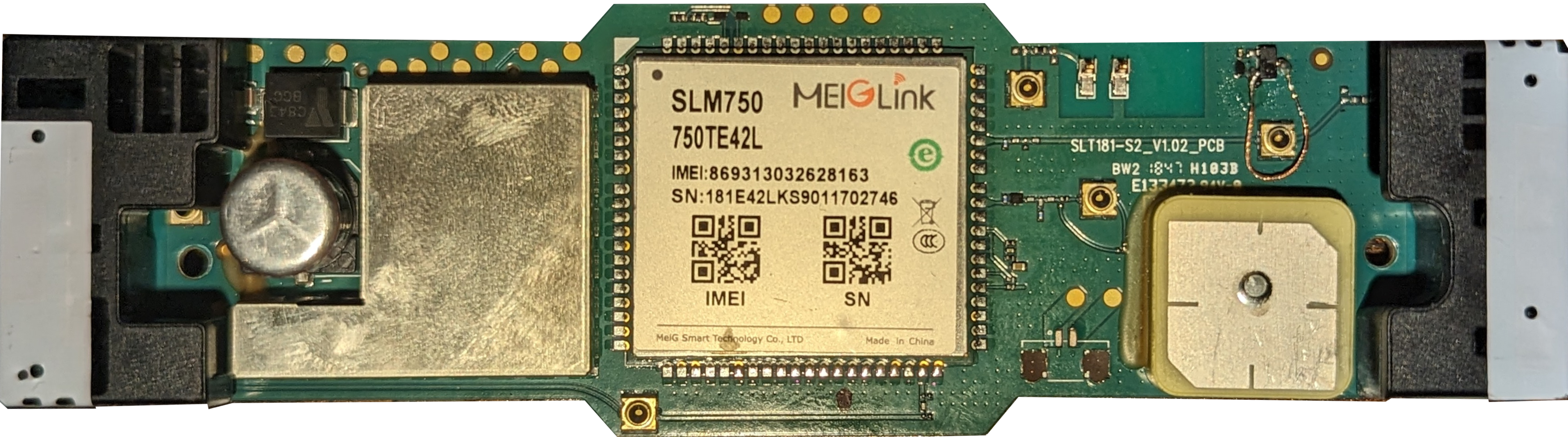
The goal of this project is to replace the IoT of the Lime Gen 3 with a custom one, so we can control it with our own app. If you find out more about the communication, please submit it here.
How it works
The IoT module gets replaced with an ESP32 microcontroller to enable us to control the scooter with our app. The app communicates with the ESP32 using Bluetooth Low Energy (BLE). The ESP32 replaces the function of the original IoT while also providing real-time feedback on speed, battery level, and other information.
Installation
Install the ESP32 add-on for Arduino IDE if you doesnt have already. Here is a tutorial. The Sketch is created with Arduino 1.8.19 for board platform esp32 by Espressif Systems version 2.0.13. Downgrade version to avoid exceeding of program storage space. Maximum is 1310720 bytes.
Install the crc library by robtillaart from the library manager.
Flash the controller with unlocked firmware.
Flash the arduino code from LimeIoT folder to the esp32.
Note: The controller gives you 42v. So you have to convert it to stable 5v for the display and the esp32. I have done it using a buck converter and ams1117.
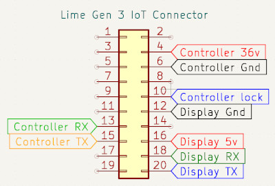
Connect the wires:
| Connector | ESP32 |
|---|---|
| Controller lock | GPIO 12 |
| Controller RX | GPIO 1 |
| Controller TX | GPIO 3 |
| Controller 42v | Buck converter -> ams1117 -> 5V |
| Controller Gnd | Gnd |
| Controller Charge (2) | GPIO 33 |
| Display 5v | 5V |
| Display Gnd | Gnd |
| Display TX | GPIO 16 |
| Display RX | GPIO 17 |
(Optional) If you want, you can connect the speaker to GPIO 13 with a base resistor and transistor. For the pcb board the speaker is GPIO 25. For more gain connect Adafruit I2S Amplifier MAX98357A DIN GPIO 27 BCLK GPIO 26 LRCLK GPIO 25.
(Optional) You can connect any alarm sensor to GPIO 14 max input voltage 4.6v (!)
Usage
You can download the app here: App.apk
The default bluetooth password is 123456789. You can change it in the ble_security.ino file.
Currently only compatible on android and is only looking good with Material You compatible phones.
If you dont want/can use the app, you can just download a bluetooth terminal app like nRF Connect (Play Store | App Store) and send the commands yourself:
| Commands | Action |
|---|---|
unlock |
Unlocks the scooter |
lock |
Turns off the controller |
unlockforever |
Keeps the scooter unlocked when disconnecting |
alarm |
let the scooter beeb (if speaker is connected ) |
Controller Communication
To unlock the controller, supply 3.3V to the blue wire connected to the IoT and send the command 464316610001F1F28F to power it on. Once powered on, send the heartbeat 4643110100084C494D4542494B45BE8A every 500ms. To power off the controller, cut the 3.3V supply and send the command 464316610001F0E2AE. The baudrate for all commands is 9600.
The command sent by the controller to the IoT consists of 42 bytes. The 9th byte represents the speed, and the 20th byte represents the battery level. The last two bytes of the command are a CRC-16/XMODEM checksum.
| Byte number | Meaning |
|---|---|
| 9 | Speed |
| 20 | Batttery |
| last two bytes | CRC-16/XMODEM checksum |
Example: 46 58 0C FF 00 22 11 00 00 40 00 00 41 3F 60 42 00 FF 44 64 52 00 61 F1 80 00 00 72 01 5C 01 59 82 00 00 00 00 E0 00 00 0A B3
Display Communication
- Baudrate:
115200 - Checksum:
width=8 poly=0x31 init=0x0a refin=true refout=true xorout=0x00 check=0xc1 residue=0x00
The following table shows the known meaning of the bytes in the commands send to the display:
| Byte | Meaning |
|---|---|
| 12 | Status (see below) |
| 14 | Battery |
| 16-17 | Speed |
| last byte | checksum |
Status Bytes:
| Byte | Status |
|---|---|
| 21 | Scan To Ride |
| 22 | Unavailable |
| 23 | Paused |
| 24 | Locked |
| 25 | Done |
| 26 | Charging |
| 31 | Driving |
| 41 | Driving Low Battery |
| 42 | Driving Alert |
| 43 | Driving No Parking |
| 44 | Driving No Riding |
| 45 | Driving Max Speed |
| 51 | Upgrading |
Example: 4C 42 44 43 50 01 10 11 00 09 01 31 01 1E 02 00 CD 01 9A
LED Communication
You can turn off the red LED with the following command: 4C 42 44 43 50 01 10 1B 00 08 03 00 00 00 03 00 00 00
| Byte | Meaning |
|---|---|
| 12 | red |
| 13 | yellow |
| 14 | green |
LED Bits:
| Bits | State |
|---|---|
| 00 | off |
| 01 | on |
| 11 | blink |
LED byte has two bits = bit for blink + bit for power