This project adds wireless functionality and an Arduino Pro-Mini compatible microntroller to an Ikea Molgan LED light with motion sensor.

- Powered from 3 AAA batteries
- Motion PIR sensor, which switches on the LED light for some time when detecting motion.
- Nice, compact enclosure
- Mounting plate
- Cheap, approx. E 4,99
- Atmel ATmega328P microntroller, compatible with Arduino Pro-Mini
- nRF24L01+ 2.4GHz radio module (not WiFi!)
- Optional ATSHA204 CryptoAthentication chip
- Default sketch implements a MySensors enabled motion sensor
- Serial connector for programming sketches
- ISP for programming the ATmega directly
- LED light function can be removed, either partially or complete, to save battery power
- Quite cheap, around E 10,- including Molgan.
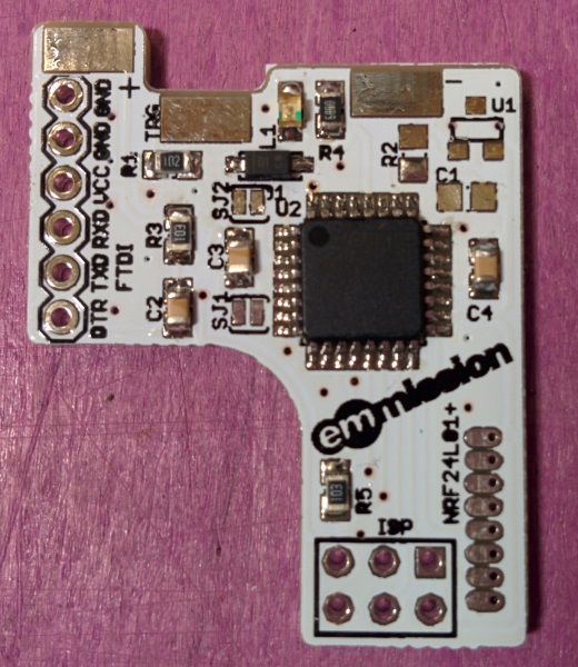
The project consists of a custom PCB, which is mounted on top of the original Molgan PCB. I had the custom PCB produced in white, to prevent it from being visible trhough the semi-transparent cover of the Molgan.
- Ikea Molgan
- Components, as described in the BOM (LibreOffice Calc format)
- An In-circuit-programmer to flash the ATmega328, or a pre-flashed ATmega328
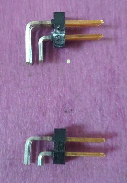
To keep the PCB small, it is built with SMD components and thus requires quite some soldering skills to put it all together! Start by mounting the ATmega328, followed by the other SMD components. The headers are the only through-hole components used, but the bottom of the resulting add-on PCB should be as flat as possible. I used a wire clipper to clip the ends off the headers before mounting them, as shown in the following picture (bottom image is after clipping).
Try to insert them without extending below the bottom of the PCB. Next picture from the side shows how flat it can be.
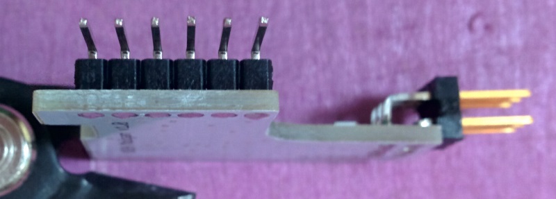
Finish by soldering the nRF24L01+ SMD module.
Remove the top cover by carefully prying something flat between the bottom and top cover. Work your way around carefully, without damaging the enclosure. The Molgan's I opened were all glued together with some double sticky tape which makes them harder to open. With the top cover removed the PCB reveals itself.
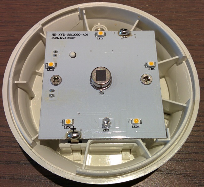
Remove the two screws and the blobs of solder als the + and - connection, which connect the PCB to the battery compartiment. Flip over the PCB.
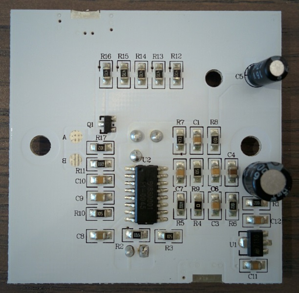
Now decide if you want to keep the (partial) LED function of the Molgan, or if you turn it into a wireless motion sensor only:
- Resistors R12..R16 are used to power the LEDs at the fron of the PCB. Removing a LED's resitor will effectively disable it.
- Removing resistor R17 disables all LEDs at once.
Solder a small wire to the right pad of R17, which will signal the add-on PCB that motion has been detected. Make it about as long as on the next picture.
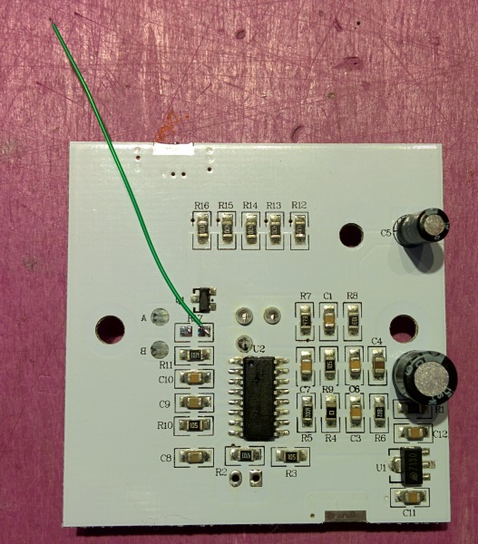
Remove the light sensor on the front (marked 'cds') or the sensor will only detect motion in the dark. I also replaced R11 by a 120 ohms resistor, to decrease the retrigger time of the PIR to less than a second.
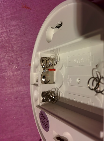
Now drill a small hole next to the battery spring, close to the mounting screw and solder a small wire to the spring base. Use a knife to scratch the surface of the metal a bit or the solder won't stick to it.
Place the Molgan PCB back into the bottom enclosure and fasten only the left screw. Align the add-on PCB on top of the Molgan PCB, as shown in the picture.
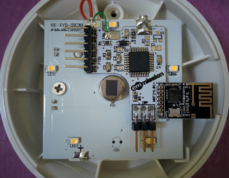
Solder the new power connection from the battery compartment to the + connection of the add-on PCB. Connect the - on the add-on PCB to the - on the Molgan PCB (I used a small piece of solder wick). Restore both connections to the batteries.
This step is required when you acquired a bare ATmega, without Arduino bootlader. I won't go into details how to do this, as the internet is full of guides, e.g. using an Arduino.
Connect the ISP to the add-on PCB, put some batteries in the Molgan and flash the default Pro-Mini bootloader (called 'ATmegaBOOT_168_atmega328_pro_8MHz.hex') which is part of the Arduino IDE, or can be found here.
Set the fuses to
- EXTENDED: 0xFE
- HIGH: 0xDA
- LOW: 0xE2
Remove the batteries and connect a standard FTDI serial cable (the ones used to program an Arduino Pro-Mini) to the FTDI connector of the add-on PCB. Replace the batteries and plug the FTDI cable in your PC.
Start the Arduino IDE and load the sketch. Change target board to 'Arduino Pro or Pro Mini' and set processor to 'ATmeag328 (3.3V, 8MHz)'.
The sketch will sleep until woken by a motion trigger from the Molgan, or wake up once every 24 hours to check battery level. It will send a V_TRIPPED message to the gateway and measures the battery level. For this it uses my Vcc library, whcih should be installed in the IDE. After a short blind time (set to 30 sec default) the motion sensor is sensitive to triggers again. This blind time prevents the motion sensor from spamming the gateway with tripped-messages. This time can also be set in hardware (by resistor R11), but software allows for easier tweaking.
The onboard LED is used as a Tx indication by the MySensors library.
Tune the sketch to your liking and upload the sketch.