Adventures in figuring out how this incredibly ubiquitous, yet incredibly mysterious integrated circuit works.
Recently, I've been looking into what it would take to include Bluetooth in my own audio projects. Reaper was a good project for learning how to do audio in a closed-loop environment, reading WAV files off of a flash chip... but what if I want to make an amplifier, or a nice pair of wireless headphones? There's some pretty good ready-to-pair modules out there (like this one or this one) for doing exactly that, but they're so expensive! I don't want to make projects with hardware that's too expensive to incorporate into real-world products, I want to learn on the actual hardware that's used to make these dirt-cheap amplifiers like this one. How are chinese engineers able to design these products to be so cheap? I started looking at more and more of these things and started noticing a trend... All of these appear to have the same 24-pin "main chip" that has an antenna, oscillator, and such directly connected to it... I tried googling the markings on these to figure out what the chip was called, but they seemed to be serial numbers, and not model numbers you'd typically find on western ICs. All I had left was the weird "JL" symbol... So I googled "jl bluetooth chip" to see what would come up, and wouldn't you know!

Holy crap, those are the chips! And a stackexchange question as the first result, mentioning something about "AC6905A" which could be the model number.
Apparently, the "JL" is the logo for "JieLi", which is the company that designed and manufactures these, and the actual model number of the 24-pin chip is the AC6905A, a low-cost all-in-one bluetooth chip found in many bluetooth audio devices made in China. Now that I know what it is, maybe I can find some sort of minimal development board containing this chip on Amazon so I can quickly get my hands on it. Searching for "bluetooth audio module" immediately brings up exactly what I wanted:

3 modules, and while the markings are absent from the chips... I'd bet my socks those are the JieLi AC6905a's that I'm looking for! 2-day shipping, let's do it.
After they showed up, the first thing I wanted to do was check to make sure they were, in fact, the JieLi chips.

And, sure enough! They are! Next thing to do was to hook them up and see if I could get my phone to pair. I wanted to see how easy they were to use from a user-standpoint before I go building these into projects.

Overall, seems easy enough. The module shows up as "HW-Audio" when given 5 volts... I didn't need to wire up and hold down a button or anything, it just automatically goes into pairing mode. Nice! I'm liking this so far.
At this point, I was really itching to hear what these sounded like. I needed to get a amplifier module that would do this chip justice. I settled on the PAM8403, a good-quality easy-to-use stereo amplifier.

Eventually, I ended up with this:

A little whine-y, but for a breadboard project, it sounds great!
So, now that I got it working, I had some more technical questions... The chip on this module is currently programmed to display "HW-Audio" as its pairing name, and there's various sounds that it plays to indicate "paired", "pause", "play", etc. If I'm going to be incorporating this chip into my future projects, I'd really like some control over what the name is, and how to change the sounds to whatever I want. But how to go about doing that? Theoretically, someone had to program this thing in the first place, so maybe I could reprogram it. And common sense would tell me someone's already done just that, so it was time to get googling.
After a while, I stumbled upon this blog post by a Chinese hobbiest named Jim, entitled "JieLi AC690X---Modify the pairing name and prompt tone"
Perfect! Exactly what I wanted.
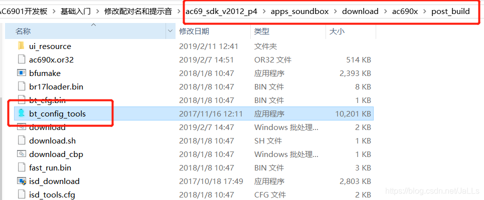
In his blog post, Jim references some software he's obtained somehow called "bt_config_tools", which appear to be part of this larger "AC69 SDK" software package for programming and interfacing with this chip. Now we're on to something!
Where do I get this "bt_config_tools" program? Well, let's ask Google again. Searching "bt_config_tools.exe" led me to a chinese clone of GitHub that someone had posted the SDK to. Great! How do I download it? Well, I needed an account. No worries, that's just a temp-email away. But... still no dice. It required contribution of my own code in order to download others'. Alright, alright... so, I zipped up my A4988 project (already public on GitHub) and waited for the site to accept it as a valid contribution. After about 10 hours, I was finally allowed to download the SDK.
Inside of it, I found all of the tools Jim had showed us how to use, and some pre-compiled binaries for the AC6905a. At this point, everything had been explained to me, with the exception of "how do I get the code onto the chip?" Unlike the PIC, STM32, and ESP8266 projects I've done before... there's no obvious "programmer" for this thing. It was time to dig deep, deep down into the depths of the Internet.
I found this Russian radio forum thread about the AC6905a, and saw that yes, in fact, there was a dedicated programmer for these chips.


Now, I've never seen anything like this before, so I knew I probably wouldn't be able to get my hands on this thing from what I've seen so far. I needed to figure out a way to do this myself, with my own hardware.
Fortunately, the same guy that posted pictures of his programmer had taken a logic analyzer to the socket, and discovered that it's really doing some pretty simple stuff to put these chips into "programming mode".

A very simple clock-and-data signal across the USB pins of the AC6905a are apparently all that's needed. I downloaded the file included in the post to look at the output for myself, and ordered up an Arduino to attempt to replicate this simple repeating signal.
From my measurements, the signal is as follows: 0001011011101111, written on the clock's falling edge.
The timing, it seems, is that every low data bit lasts 19.33 microseconds, and each high data bit lasts 19.21 microseconds. Each low clock signal lasts 9.625 microseconds, and each high clock signal lasts 9.667 microseconds.
Each falling edge of the clock comes an eighth of a microsecond behind the change in the data bit, and then at the end of this sequence, the clock goes high for 11.21 microseconds and then goes low for almost exactly 7 microseconds. Then, the whole thing repeats! Sounds pretty Arduino-able.
For those that are curious, here is my Arduino sketch for replicating this signal. You'll notice that the microsecond delays don't match what I've said above, but that's because I've taken into account how long it takes the Arduino to process commands and change GPIO signals, so the actual output is accurate to within about a half a microsecond.
And the best part is, it works! When the clock pin of the Arduino sketch is connected to the D+ pin of the AC6905, and the data pin of the Arduino is connected to the D- pin, the AC6905 shows up under device manager as BR21 UBOOT1.00 USB Device shown here:

Interestingly enough, back in Jim's blog it showed up as BR17, not BR21 ... maybe I have a newer chip? either way, I pressed on. I knew by now through messing around that the tool to actually "upload" the program to the chip was called isd_download.exe, and after some more messing around, I learned that the way to use it was to pass it command-line arguments on run. So, for instance, isd_download.exe -dev br17... but if I ran that command myself, the program would complain that it couldn't find a BR17 on my computer! "Easy enough to fix", I thought. "I'll just try isd_download.exe -dev br21". Well, now it complained it couldn't find a file called br21loader.bin. But there was a br17loader.bin present, so I tried renaming that to br21loader.bin to see if that would push it through... This time I got a boatload of errors back from the chip, but that was fine because that meant I had managed to communicate with it! One of the things it complained about was that the keys didn't match... Which is unfortunate, because that means these things have some sort of security feature which prevents any old firmware from being loaded onto them. Makes sense, I guess. I tried longer commands with more arguments, to try and pass the keyfile that came with the SDK into the program to see if that would work, but still no dice. At this point, I wondered if it would be best to start with some blank chips to mess around with.

On Aliexpress, they're $10 for 10 chips, plus shipping. Not bad, but I'm guessing in bulk they cost next to nothing.
After a couple of weeks, they arrived!

All 10 came in a tube with tape at the end. Pretty much the same thing I got my STM32F030F4P6s in. I also ordered a QSOP-24 breakout board from ebay to breadboard these things.
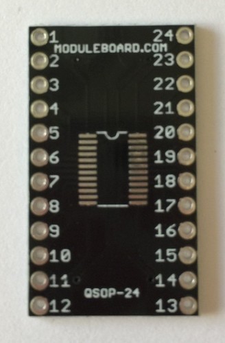
But... I didn't have a solder stencil for this footprint, so I'd have to be extremely careful with soldering. Furthermore, I only ordered 1 breakout board! That meant I only had 1 shot to get it right.
After about 20 minutes of delicate maneuvering and deliberately-placed solder paste, I had what appeared to be a successful operation!

Pins 21 and 22 did appear to give me trouble at one point, though. While I was checking each pin to make sure it didn't bridge with its neighbor, these two indicated they had a dead short between them. But, of course, I didn't see any bridge, so I thought "maybe these are shorted together within the chip die."
So, I took a second chip out of the tube, and sure enough! My multimeter detected a dead short between pins 21 and 22 on a bare, unaltered chip.

According to a diagram I found during my forum-hopping, pins 21 and 22 are the antenna and one analog signal ground. While my current grasp of analog RF circuitry is limited, I suppose it's reasonable to assume the impedance between the antenna input and ground is quite low.
Alright, now we need to see if we can get this thing to talk. After discussing with one of the forum users, I arrived at this minimal configuration for the AC6905A to boot up.

And then, after agreeing, I built it on a breadboard. I didn't have a 24MHz crystal lying around, so I used a 26MHz instead. I didn't need a radio yet, so I hoped this would be close enough for USB at least.

To my surprise, it booted up first try! It even appeared in Device Manager as "BR17 UBOOT2.00 USB Device" without requiring my Arduino programmer.

In hindsight, this makes sense, since it's a blank chip and has no "main" program to load into.
Unfortunately, I still had issues getting the chip to let me upload firmware.