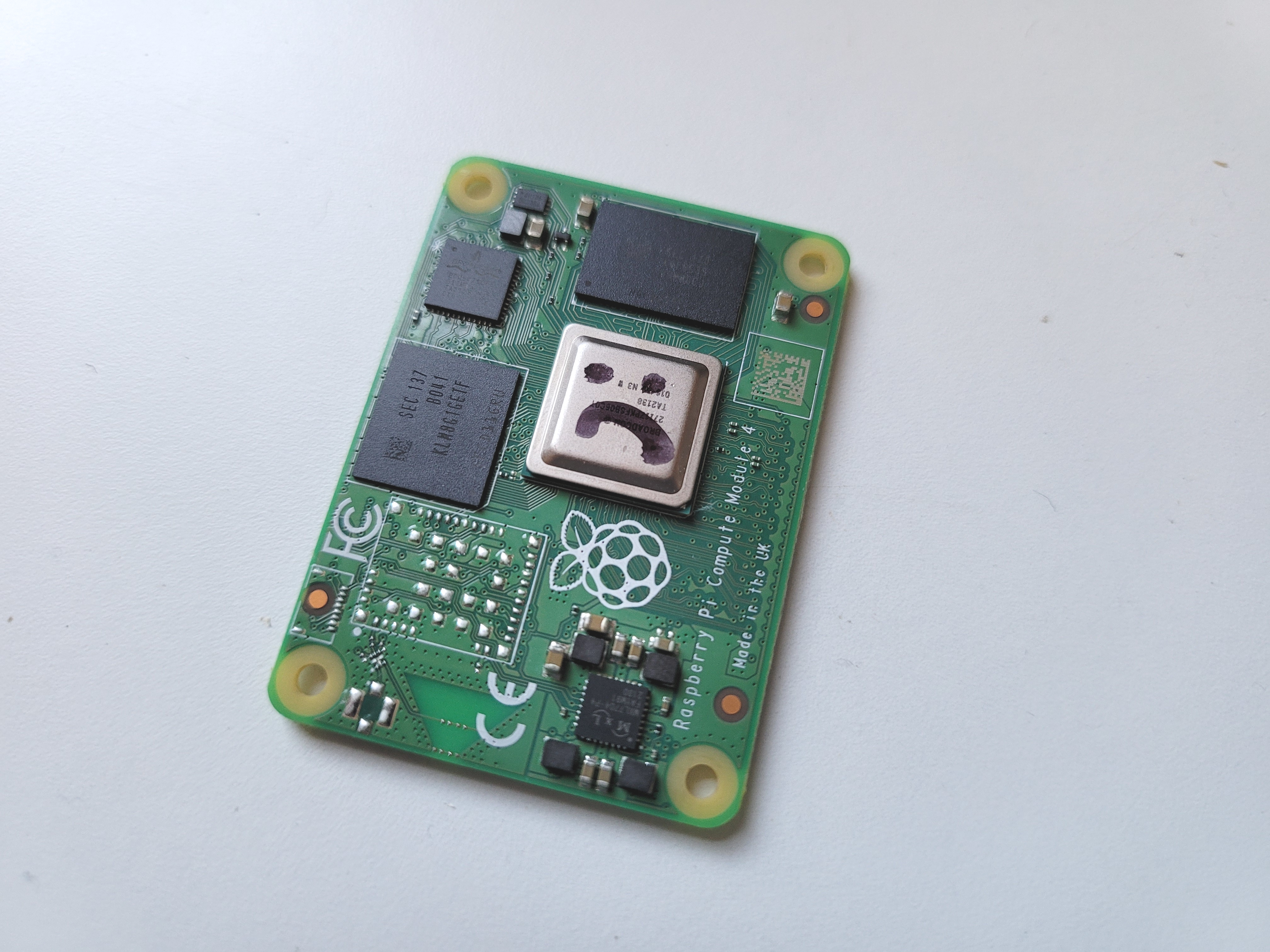
I like the CM4, but it's pretty easy to blow it up. The PMIC doesn't have any kind of overcurrent protection, so if you short any rail to ground, or any pin driven high, it will die. Replacement PMIC's are almost available, but not quite. Earlier versions of the chip are on sale from Mouser, etc., but not the P4 revision that's on the Pi 4 / CM4. That may have changed by the time you're reading this. In any case, replacing the PMIC won't help if your SoC is also dead.
I've blown up three of them so far by doing various stupid things. They're not expensive, but if you've got some critical data stored on one and it ain't backed up properly - expect trouble.
To avoid cross-compilation I had been doing quite a lot of work on the Pi itself, working on a custom kernel module. I hadn't noticed, but a pile of vital files weren't checked into git, and I'd been a bit sloppy with regular pushes anyway, so, when I accidentally dropped a scope probe on the PCB, dread gradually crept over me.
Luckily, eMMC chips are electrically compatible with [micro]SD cards, so all we need to do is convert the dead CM4 into an SD card. What follows is a description of how I figured out how to do it, and a guide for you to follow if you find yourself in a similar situation. I've gone into some detail because you could use the same method for other Pis, or other SBC's for that matter.
There is an alternative solution - tools exist that can directly read a desoldered eMMC chip. They are used by people who recover data from phones. However, it would have taken several days to get my hands on one, and they're pretty expensive for a single-purpose tool.
In principle, all we need to know for this hack is the locations on the CM4 board of each of the eMMC bus signals. Once those are known, we can connect them to something that can read SD cards, e.g. a USB SD reader and suck out the data.
First I needed a sacrificial CM4. Luckily one was available (see above) so no problems there. I removed various chips to get access to the signals, then traced them out.
I've done this once, so you don't have to do it yourself unless you're working on a different platform.
I don't have an x-ray machine, so I had to probe around with a multimeter like a caveman. Where to start? Well, we know the signals need to get to the pads of the eMMC, so I desoldered that with a hot-air reflow station.
The signals start at the SoC, so I removed the head spreader by gently prying it off with a scalpel, then removed the SoC with hot air. Be patient when doing this - the part has underfill glue, so it really takes some heat before it lets go. On my first board I got a bit impatient, started prying with a scalpel, slipped and mashed a load of pads. Luckily none that I needed to access.
Next I removed the PMIC - I knew it was dead, so it would probably interfere with the power rails.
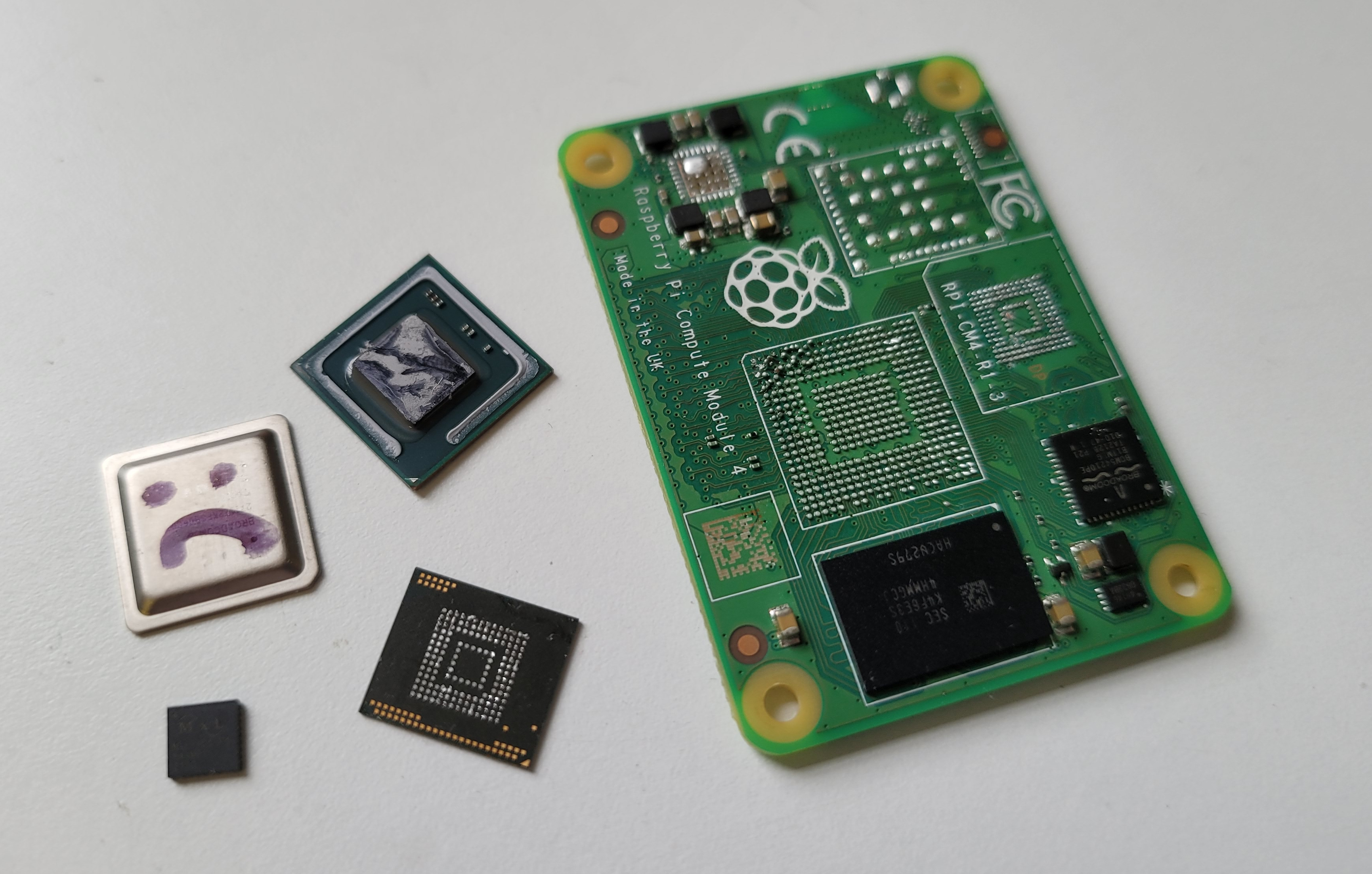
After all that, I had this sitting on my bench.
Next up, I needed the pinout for the eMMC. The part on my CM4 is a KLM8G1GETF. I found the datasheet on a dodgy phone repair site, but it doesn't matter if you can't get the exact datasheet for your part - eMMC's in the same package have compatible pinouts. I've mirrored the datasheet here.
Here's a snap of the pinout from the datasheet:
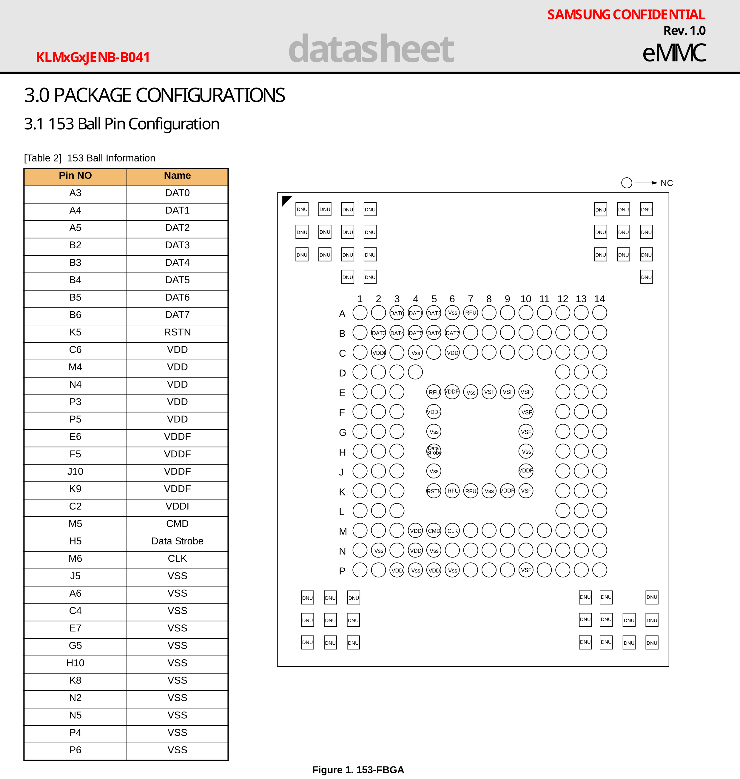
A normal SD card has a 4-bit data bus, an eMMC chip has an 8-bit one, but, luckily, both can operate in a slower, single-bit mode. That means we only need to connect these six signals from the Pi's eMMC to the SD reader:
| Signal | Function |
|---|---|
| VCC | 1.8V / 3V power rail for memory controller |
| VCCF | 3V power rail for flash memory |
| GND | Ground |
| CMD | Data direction indicator |
| CLK | Clock signal |
| D0 | 1-bit data line |
You can safely connect VCC and VCCF together, both can handle 3V. There are 1.8V access modes, but they require negotiation from the controller. I've only spent a couple of minutes reading about this, though, so if you're recovering a million BTC hardware wallet I suggest you test on some disposable hardware first.
With the chips off, looking down the microscope and working with the multimeter in continuity mode, it only took a couple of minutes to beep out the signals.
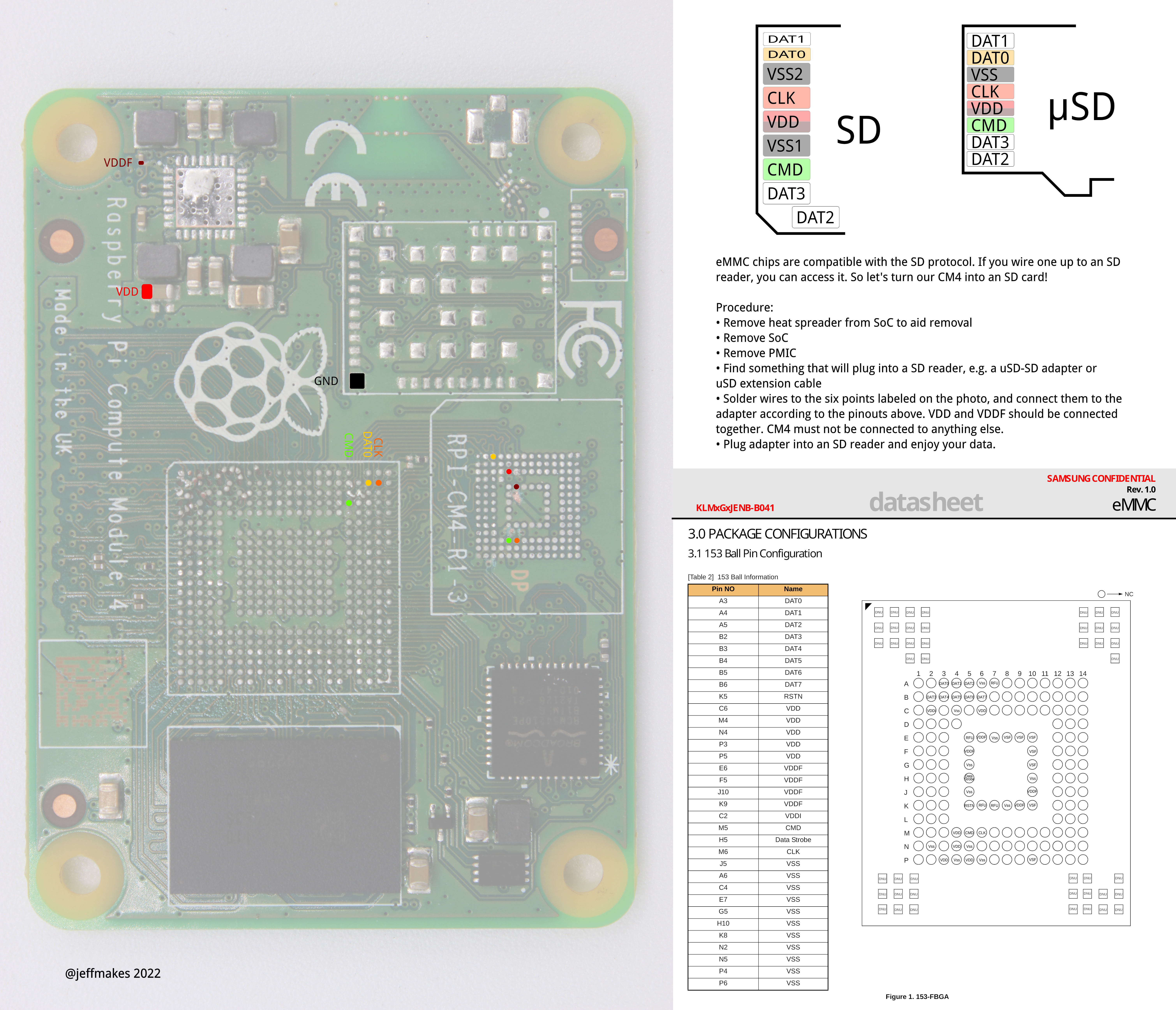
Here's a giant one-pager that shows the points on the Pi's PCB where the eMMC pads can be accessed without removing the eMMC itself. If you don't want to, you might not need to actually remove the SoC. You'll see there are vias or portions of accessable traces where you could solder on wires instead of using the SoC pads. It won't be much easier than soldering to the SoC pads, since they're about the same size as the vias, but it may be an option if you don't have a hot air tool. That said, the SoC might interfere with the signalling, particularly if it's toasted, and if you're on a different platform there's the chance some tracks might be totally hidden on an inner layer. Generally, I'd recommend removing the SoC if you can.
Now I knew where to solder to, I could switch my attention from the sacrificial Pi to the target Pi containing the valuable data and start making connections.
Once the anaesthetic wore off, the patient looked like this:
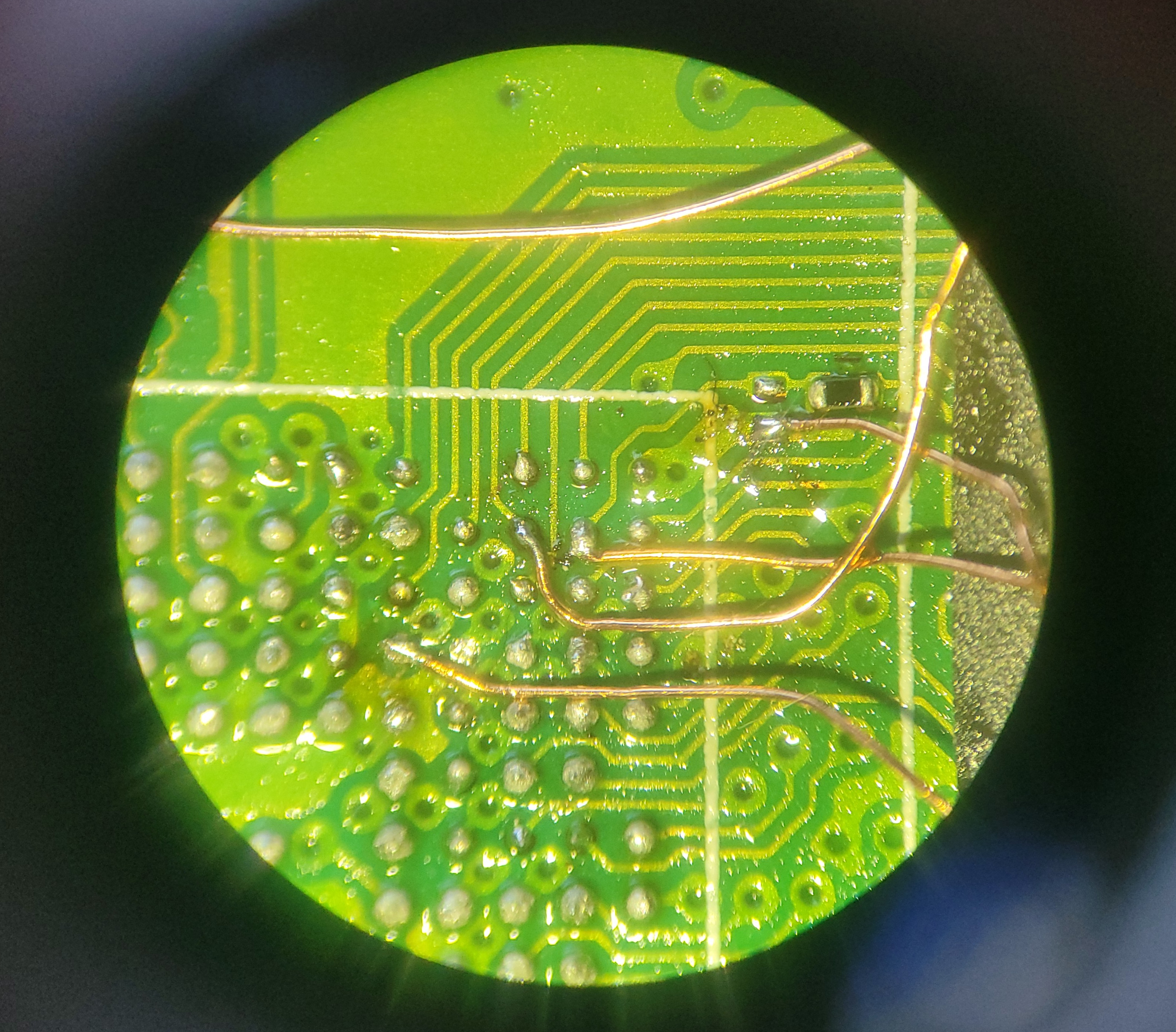
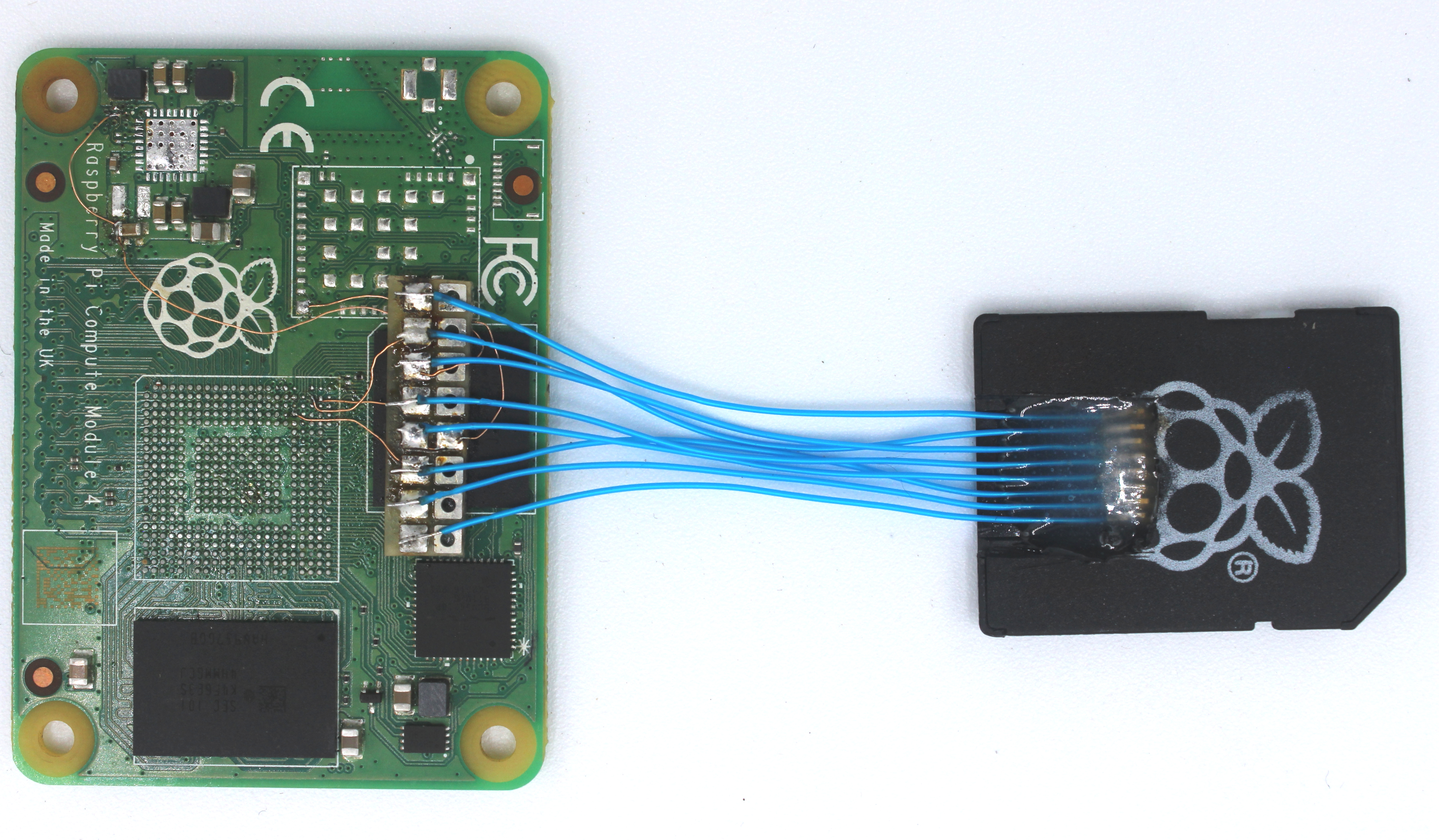 In the centre, stuck to the eMMC with some double-sided tape, is a 8x2 piece of matrix board. This is simply there to provide strain relief. I used some 0.1mm diameter enamelled wire to connect to the eMMC signals on the Pi. It worked nicely. You should use the narrowest stuff you can get, otherwise you'll pull the pads off the board.
It's a 0.5mm pitch BGA, so you'll need tons of light and some magnification. Here's a view down the microscope:
For the SD connections, I took a uSD-to-SD adapter, carved a hole to expose the uSD contacts, and soldered on eight pieces of 0.3mm Kynar wire. I potted the assemly in some 5-minute epoxy to prevent adjacent pins from shorting together. They were surprisingly mobile. Once this SD-to-wire assembly was cured, I soldered it onto the matrix board.
There are many ways to skin a cat, and you could definitely make something jankier that would still do the job. If I was in more of a hurry I would have just sacrificed my USB-SD reader and soldered wires from its PCB straight to the Pi. The area where you absolutely must not cut corners is the strain relief - if you peel off a track you'll find the whole enterprise rapidly turning pear-shaped.
Here's where I started to breathe a sigh of relief - happy bytes flowing off the eMMC and into my USB port. Even in 1-bit mode it took less than half an hour to image the full 16GB.
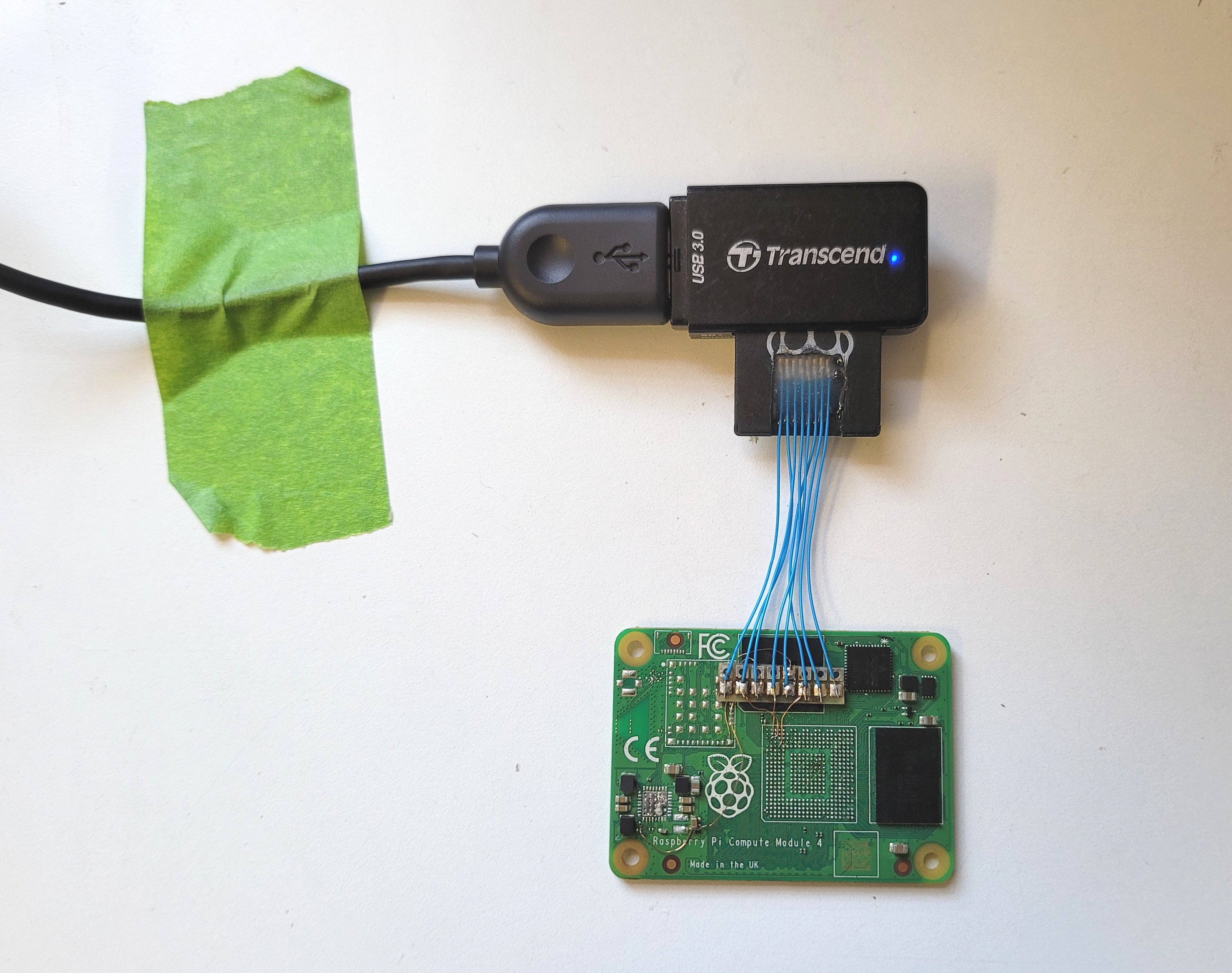 Note again: more strain relief.
To close, it probably goes without saying, immediately take a full image of the eMMC using dd or the tool of your choice. You don't want to be buggering about browsing the files on the chip then have it get hit by an asteroid before you get all the data off. This is trawling, not spear-fishing - archive the whole thing, and do the forensics afterwards with your feet up.
