CFD Solver for heat transfer simulations between solid and fluid regions with an implemented model for thermal phase change of pure substances in fluid regions. Algorithm is tested and validated for thin film applications with laminar flow.
Technical University of Munich, Institute of Plant and Process Technology
© 2019 Thomas Kleiner, Sebatian Rehfeldt, Harald Klein
tpcMultiRegionFoam is a developed CFD solver, using the OpenFOAM 6 libraries, for transient heat transfer simulations between thermally coupled solid and fluid regions with pure substance condensation/evaporation. The solver builds a combination of the chtMultiRegionFoam and the interFoam solver developed by OpenCFD Ltd. and is extended by a phase change model for pure substances. The model validation and mathematical formulation are given in Kleiner 2019.
If simulations with this solver or ideas deducted from this repository lead to a further publication, the before mentioned article (Kleiner 2019) should be cited.
For installation, the OpenFOAM 6 libraries have to be loaded.
All necessary applications for the solver installation can be installed and uninstalled by the supplied Allwmake and Allwclean shell scripts, respectively. The scripts are located in the solver folder.
Copy the content of the solver directory in your desired user applications folder and run the Allwmake script.
Working folder:/home/<user>/OpenFOAM/<user>-6/applications

$ cd /home/<user>/OpenFOAM/<user>-6/applications
$ cd solver
$ chmod 700 Allw*
$ ./Allwmake
Two test cases, a 2D and a 3D test case, are provided for a transient simulation of pure substance condensation on a horizontal tube. Two regions are considered in both simulations. One solid region for the tube and one fluid region for the two phase system. Both Regions are thermally coupled at the outer tube wall. A constant heat flux is withdrawn from the inner wall of the Tube. The initial state of the simulation consists of a pure vapor phase at saturation conditions with a temperature of 309.15 K (n-pentane, 1.013 bar). The initial tube temperature is also set to 309.15 K.
In the first couple of time steps, the tube is cooling down and no condensate is formed until the temperature change reaches the outer tube wall. Condensate is formed, as soon as a temperature decrease below saturation conditions would occur in the fluid region.
Since a very thin condensate film is formed within the simulations, high computational effort is necessary for a very good quantitative agreement with measurements. Since we aim to give an insight in the simulation set up with the provided test cases, they have a lower mesh resolution and a higher time step size compared to the simulations published in (Kleiner 2019).
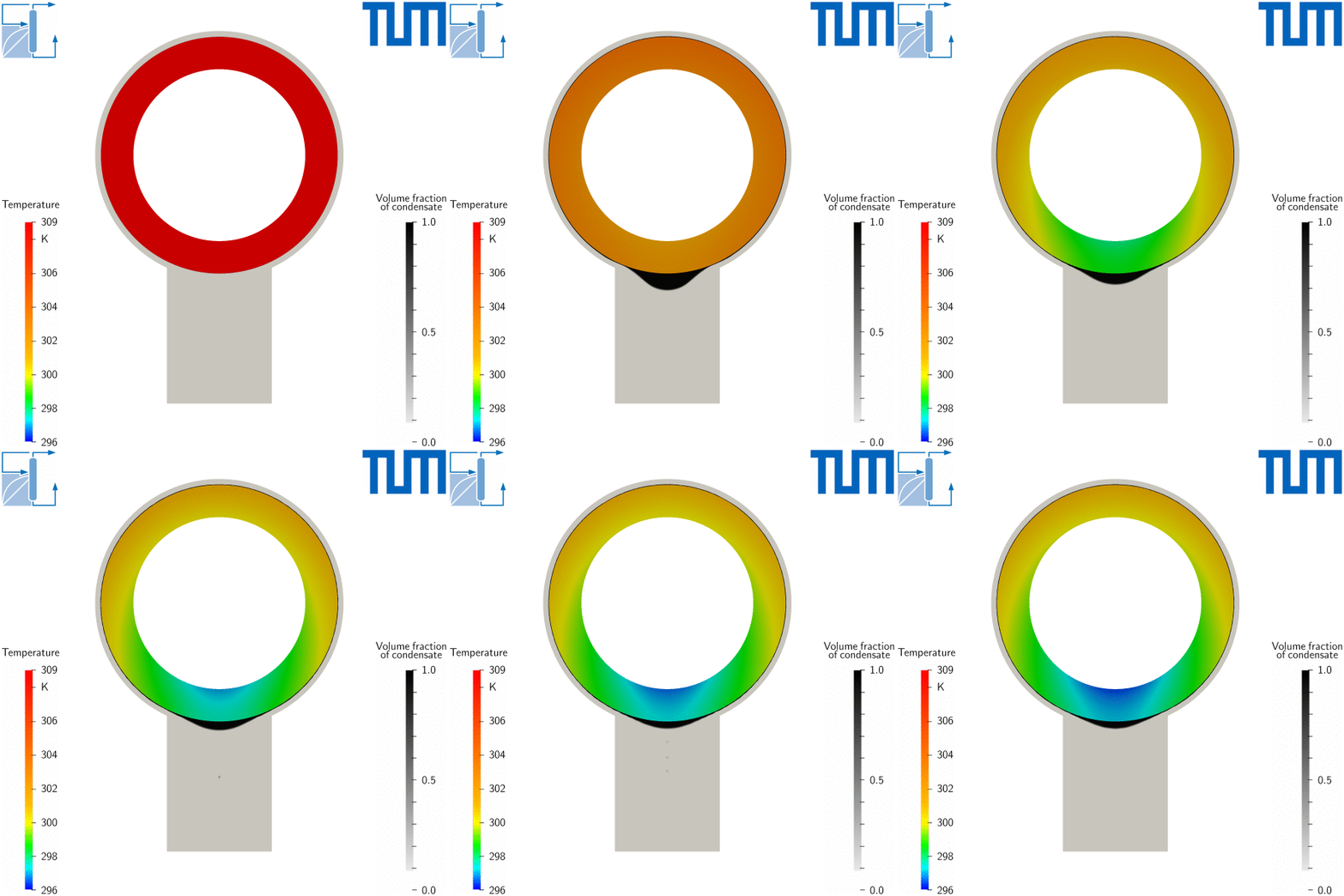
The presented results of the 2D simulation shows the tube’s temperature field in the rainbow scale and the fluid’s volume phase fraction field in the grey scale.
In the beginning of the simulation, the tube temperature decreases and an initial condensate film is formed. Afterwards a drop is formed at the bottom of the tube, which eventually drips off. The simulation reaches a state, where condensate drips off periodically. The increase in thermal resistance due to the condensate film can be observed at the lower part of the tube, where the changes in the temperature field stand in accordance with the drip-off frequency.
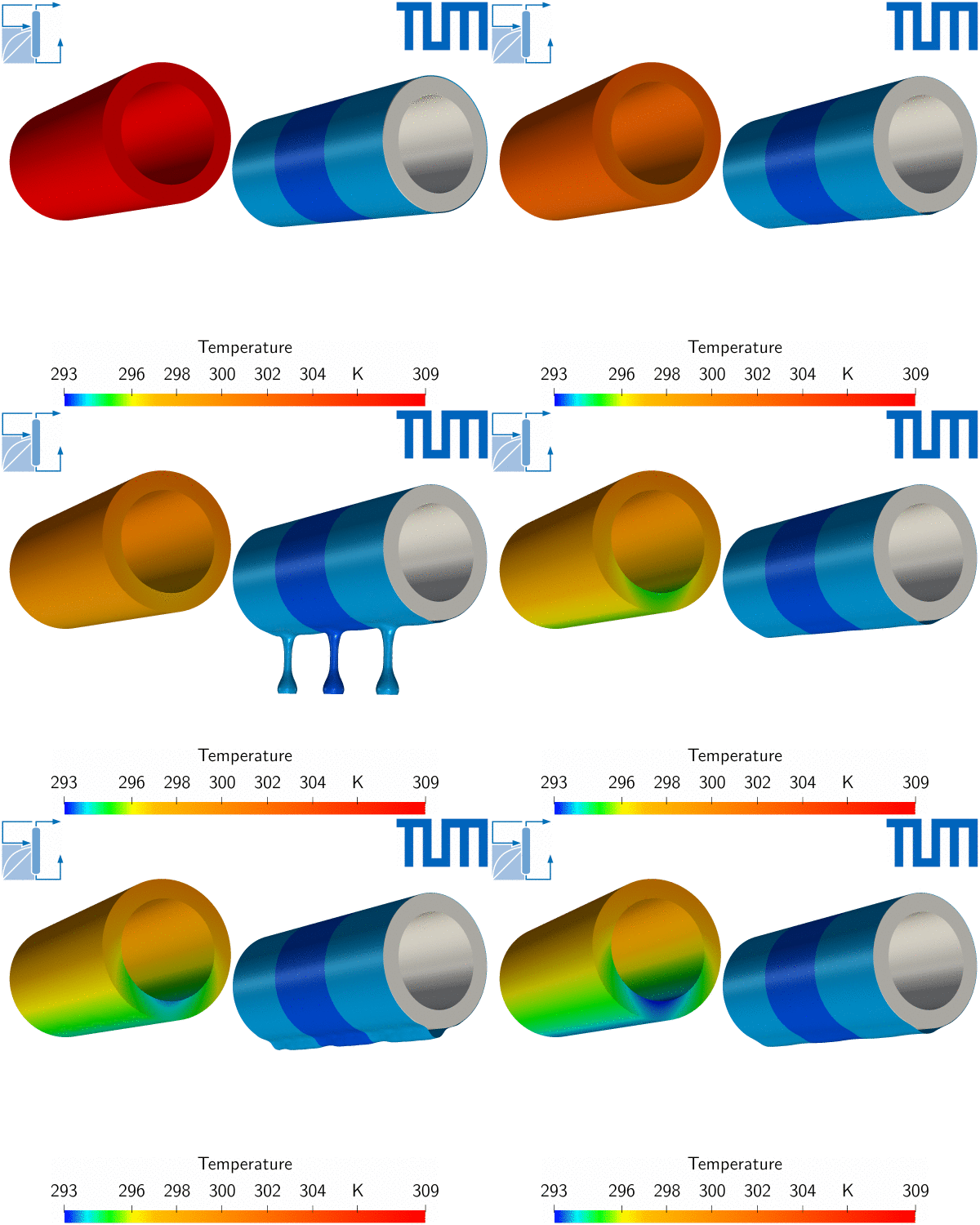
The presented results of the 3D simulation shows the tube’s temperature on the left side and the interface of the condensate on the right side. The actual simulation domain is given in the darker blue shade. The simulation results are expanded by an additional domain to each side for a better visual representation of the results. Additionally a thin initial film is provided in the simulation to reduce computational effort.
The setup of the 3D simulation is the same as for the 2D simulation except, that the simulation domain in axial direction is expanded and cyclic boundary conditions are used for the boundaries normal to said direction. The length of the simulation domain is equal to the most dangerous wavelength of the thin film Taylor instability of n-pentane.
- T. Kleiner, S. Rehfeldt, H. Klein, CFD model and simulation of pure substance condensation on horizontal tubes using the volume of fluid method, Int. J. Heat Mass Transf. 138 (2019) 420-431, https://doi.org/10.1016/j.ijheatmasstransfer.2019.04.054.


