I have always wanted was to make lights dance to music. However, I found it was difficult to make something impressive - anything beyond a simple FFT mapped colors.
It all started when I found an open source project that provided the required materials and code to process an HDMI signal and light up LEDs on the back of the TV. After buying all the materials, I realized that I might have underestimated the effort required to make it worth it.
When it came time for me to choose a capstone project this idea seemed to fit perfectly as it aligned with many different areas of computer engineering.
TLDR: I like colors.
This project will use a Raspberry Pi and an FPGA to achieve the dynamic back lighting for a TV. The Raspberry Pi will be running a static web app and a web server. The app will talk to the web server using HTTP requests to configure the system. The web server will be talking to the FPGA over the Pi’s UART connection. The web server will also be able to generate patterns to be displayed on the LEDs. The FPGA will be doing the image processing for the system, calculating each of the individual backlight colors, and communicating with the LEDs on the back of the screen. In front of the FPGA a HDMI duplicator and downscaler will allow the source image to continue to the screen and be handled by the FPGA. This project was inspired by a blogpost on zero characters left.
Since this project was used as my Computer Engineer Senior Design project, I had to come up with a project mission statement:
The objective of this project is to design and prototype a device that will improve the
immersion of videos by adding dynamic back lighting to a monitor. The device will contain a
micro controller and FPGA to control and configure the system. The user will communicate with
and configure the system through an application. After configuration, the system will function
autonomously and will not need input from the user.
To start I want to go over some basic background information on technology in the project that most people might not be familiar with: FPGAs and how Video Signals work
FPGAs are one of the coolest pieces of technology (conceptually at least) I have ever worked with. The basic idea is that you can build programmable hardware that is really good at one task. They lie somewhere in the middle of a GPP (general purpose process such as the CPU in a computer) and a ASIC (Application specific integrated circuit). They work by building hardware logic gates using Look Up Tables (LUT). For example, a two input AND gate can be designed using a LUT like:
          ____
L|0| ->  | M  |
U|0| ->  | U  |-> A&B
T|0| ->  | X  |
 |1| ->  |____|
          |  |
          A  B
Or the LUT can be a programed differently so an OR gate can be represented.
          ____
L|0| ->  | M  |
U|1| ->  | U  |-> A|B
T|1| ->  | X  |
 |1| ->  |____|
          |  |
          A  B
FPGAs are "programmed" using HDL, Verilog or VHDL, that describes how the logic acts. The compiler then takes the HDL and converts it to a bit file that is used to configure the hardware present on the FPGA. This involves programming all the LUTs on the board. HDL is similar to HTML in that it is descriptive: it describes how the FPGA should act. None of the HDL that is written is executed during the FPGA run time, mostly because there simply is no runtime.
FPGAs are more expensive, "slower" (I physically could not have the fpga work at a speed required for 4k), have a much larger physical footprint, and have a more limited general compute power than their ASIC counterparts. However, their ability to be re-programmed, their low entry cost, and the ease of making changes to logic make FPGAs a viable solution for a wide range of applications. One area they excel is when dealing with any sort of real time signal processing. If you wanted to read a high bandwidth signal off a wire, a general purpose processor, or GPP (Arduino, ARM), you would need to fire an interrupt, read the signal, add that signal to a buffer, then find time between interrupts to process the signal. The higher bandwidth the signal is, the faster the processor needs to be. However, assuming the signal is within the required frequency, a FPGA can work on all those steps in parallel. One set of LUTS can be focused on reading the signals, one set can be reading/writing to shared memory, while another is doing any sort of processing. A GPP could then read the processed memory basically for free.
As someone who has taught FGPA design, the hardest conceptual leap is understanding the parallel nature of what you are building. When looking at traditional code, each instruction is sequential, as a processor can only perform one instruction at a time. If you carry that mindset over to FPGAs, you're going to have a bad time. On an FPGA, multiple things can happen simultaneously.
For example, the flowing VHDL code with signals A, B, C:
if rising_edge(clk) then
  A <= B;
  C <= A;
end if;
Most people would assume that on each clock cycle, first A gets set to B, then C get set to A, thus C = B. However, this is incorrect. Both A and C get updated at the same time, thus, after each clock cycle: A = B and C = A' (whatever A was BEFORE the clock ).
Here is a good post I found to give some more background on a FPGA: http://www.righto.com/2018/03/implementing-fizzbuzz-on-fpga.html
Almost all video signals operate the same way. While the way they are transported differs widely depending on the medium, (HDMI, DVI, Display Port, compressed/uncompressed) they all end up becoming the same right before they get displayed on the screen. This is usually seen in a 40-pin ribbon cable.
- Pixel Clock: High* when there is valid information on the other signals
- Pixel value (24 bit): the three byte pixel value in RGB form
- H-sync: High* when the current pixel is the last pixel on the row
- V-Sync: High* when the current pixel is the last pixel on the screen
To tie these signals to some common TV terms: A screen with a 60 Hz Refresh rate will have V-sync high* 60 times a second A screen with resolution of 1920x1080 will have a h-sync high* every 1920 pixels, and there will be 1080 of them for each V-Sync
*Assume Active High Signals
The system will be split into two main parts:
- A web server running on a Raspberry Pi
- An FPGA doing video-image processing.
Required external ports of the system are as follows:
- An HDMI input to get the video stream to the system
- A serial interface to control the LEDs
- An internet connection to access the web server
The pre-processing hardware first involves an HDMI duplicator so the monitor can have access to the original video stream so the system does not have to recreate it. Then, the second HDMI signal is fed into an HDMI downscaler, which will convert whatever the HD resolution is into a 720p signal to be fed into the FPGA via an HDMI port. The FPGA and Raspberry Pi will use UART communication to communicate with each other.
                HDMI -> Monitor
               /
HDMI -> Duplicator
\
HDMI -> Downscaler (converts to 720p signal) -> FPGA HDMI port <-UART-> RPi
The RPi is there to program the FPGA and host a flask app for the frontend user interface.
Flask takes care of configuring the HTTP server endpoints, allowing for quick and easy development of the REST API by mapping URIs to Python functions. The Flask app will use Python’s serial library to read and write to the external UART communication pins on the Pi. Flask will also serve up any static content.
The frontend is an angular JS app with a Flask backend that allows for the control and configuration of the project.
Messages from the frontend to system are JSON based. They contain at minimum an ‘op’ command and any parameters needed by the system.
{"op":"set", "what":"mode", "to":"on"}- turn on the device
{"op":"program"}- tell the pi to write to the FPGA registers
{"op":"set", "what":"vert_leds", "to": 50}- set how many vertical LEDs are on the TV
{"op":"get", "what":"mode"}- get the current mode from the server
The FPGA will be the core of the image processing portion of the project. Within the FPGA, configuration registers will be used to configure FPGA as well as to house the mapping between the pixel accumulators and the backlighting LEDs. The color averaging algorithm will be preformed by the FPGA. Then, using the pixel mapping configuration registers, the FPGA will write the output of RGB values to the individually addressable LEDs used as the backlighting LEDs. This output will be performed using a serial interface coded specifically for the LED strips. The FPGA selected was the Xilinx Spartan 6XL25 on the Mini-Spartan 6+ for built in HDMI inputs and larger LUT count.
The best way to handle the accumulation of the pixel block values is to have dedicated accumulators for each color average block. This is the design of the blog post. Translated to python code, each color average block would look like this:
if rising_edge(pixel_clock):
   if v_sync = 1:
      block_r = 0
      block_g = 0
      block_b = 0
   if current_x >= block_start_x and current_x < block_size:
      if current_y >= block_start_y and current_y < block_size:
         block_r += current_r
         block_g += current_g
         block_b += current_b
What’s important to remember is that for each color block, hardware that performs this action is generated so that each color block can function in parallel. No matter where it is on the screen on each pixel clock, the if statement that checks the current_x and current_y will execute num_blocks all at the same time. The start position of each block can be calculated using a python script and then fed into a VHDL generate statement to position.
One interesting side note is that with this method the average color of any area on the screen can be found by just changing the start locations and size of the block.
For this project the block size used was a power of two, allowing for division to be accomplished by a shift.
The FPGA will receive commands over UART using a command-payload structure. UART was selected due to its ease of implementation and supporting the required speeds. An open-source UART controller will provide the Rx and Tx interfaces. A state machine will then be used to decode the commands and payloads to their appropriate registers. Other signals were looked at (i2c, SPI) but because of the simplicity of the interface a UART was all that was needed. The communication follows a command-expected payload structure. For each command sent, the FPGA is expecting a set number of bytes to follow.
|Description|Hex Value|       Payload       |size bytes|
|-----------|:-------:|---------------------|----------|
|mode       |0x00     |mode select          |   1      |
|counts     |0x01     |[]led per block      | num_leds |
|effect     |0x02     |[]custom block values|num_blocks|
In order to make this project work on a wide range of screen sizes, there needs to be some way to map the color blocks to LEDs. Originally, a mux was used to map each block to each LED. The Pi could then program the selects of each mux to route the colors in different locations. This naive approach had the downside that each mux would need (num_blocks) * 24 inputs, and would require num_leds mux's. While this worked for a small number of LEDs and blocks, when scaled up to a large number of LEDs the number of required mux's quickly outsized the FPGA. This also required that there is one 24 bit register for each LED.
After a few other methods of trial and error, it was discovered that it is unfeasible to store each output LED value on the FPGA. Instead, if the Pi is programmed the number of times each color block needs written out, all that is needed is one 8 bit register for each color block. All Pi had needs to do is know how many color blocks and LEDs there are and calculate how many times each color block needed to be written out
For example, in the simple case, if there are 10 blocks located across the top of the screen, and 10 Leds across the top then each block will get written out once. If there are 5 blocks and 10 leds, each block gets outputted twice, and 5 blocks and 9 LEDs, the output will look like: [2,2,1,2,2]. Below is the python code the server uses to calculate this distribution around the screen.
"""
caululate the led mapping and then write it out to the fpga
"""
def write_pixel_mapping(self):
        # both of these should be >=1
        num_horz_leds = System.num_horz_LED
        num_vert_leds = System.num_vert_LED

        num_vert_blocks = System.numVertBlocks
        num_horz_blocks = System.numHorzBlocks

        values = []

        leds_per_block = num_horz_leds / (num_horz_blocks * 1.0)
        for i in range(0, num_horz_blocks):
            values.append(int((math.floor((i + 1) * leds_per_block) - math.floor((i) * leds_per_block))))

        leds_per_block = num_vert_leds / (num_vert_blocks * 1.0)
        for i in range(0, num_vert_blocks):
            values.append(int((math.floor((i + 1) * leds_per_block) - math.floor((i) * leds_per_block))))

        values += values[::-1]
self.write('counts', values)The FPGA also supports programming of custom colors for each block. This allows for the leds to be used like a standard LED light strip. Time did not allow for me to implement this on the raspberry pi but was really fun to play around with.
Xilinx can produce schematics for all the vhdl code that gets written.
Looking at the schematics has helped me in the past at visualization
a mistake with a connection. It will go as far as showing all the LUTS
but for the most part just becomes noise once you zoom into the lowest level.
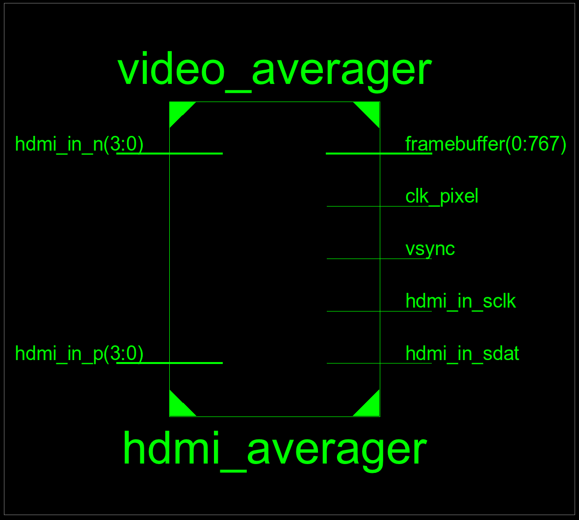
At the top level the inputs and outputs of the FPGAs are displayed
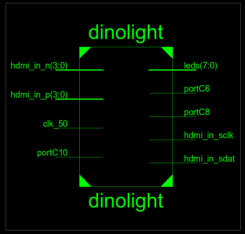 The wires C10, C6, C8 are all tied to a pin on the FPGAs board and map to the Rx, Tx, and neopixel control respectability.
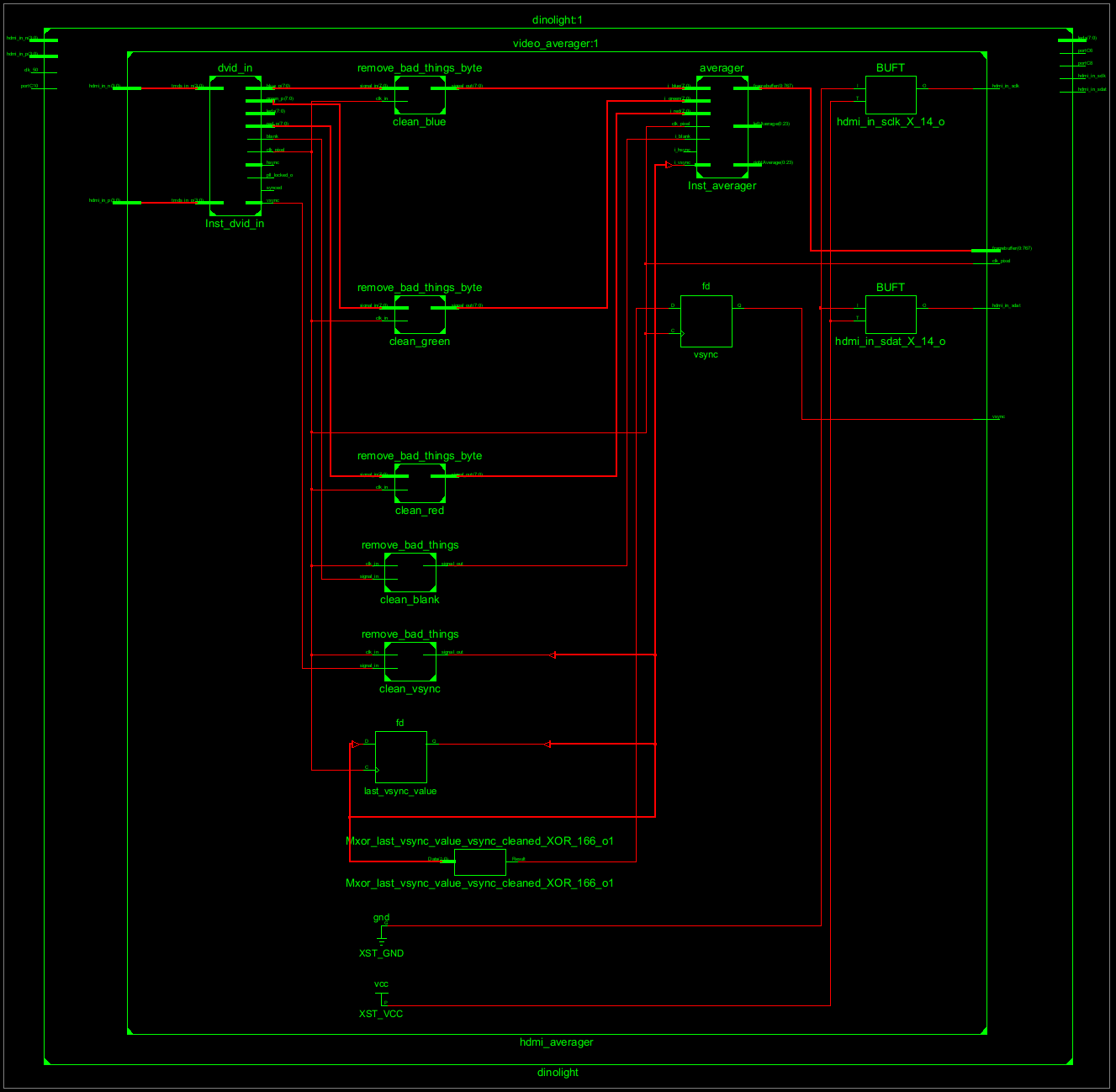
Opening the level 0 we can view all the different subcomponents.
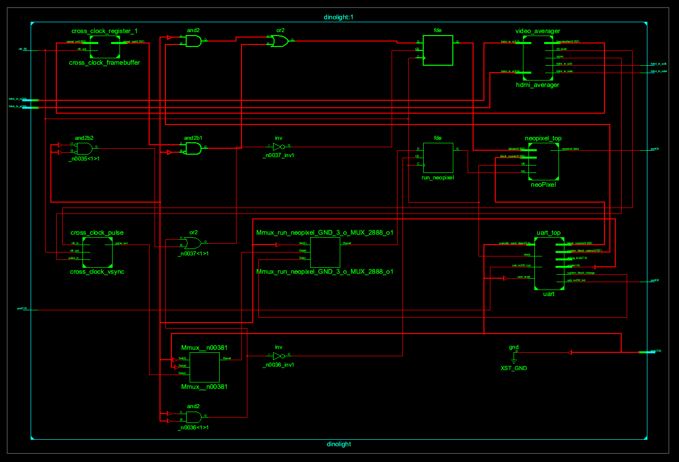
The important components are the ones on the right.
- UART accepts serial connection and sets configuration registers
- video average accepts the HDMI signal and outputs average blocks
- nonpixel driver for driving neopixels
The cross clock components are there to cross the signals from the HDMI clock signal domain into the FPGA clock signal domain.
The left is the opensource core that converts the HDMI signal into the RGB, h-sync, v-sync, and pixel clock signals. The averager core is on the right The components in the middle are basically a low pass filter to remove occasions when the div core would randomly drop low for a single clock cycle. Instead of debugging the DIV core I just put these buffers in place.
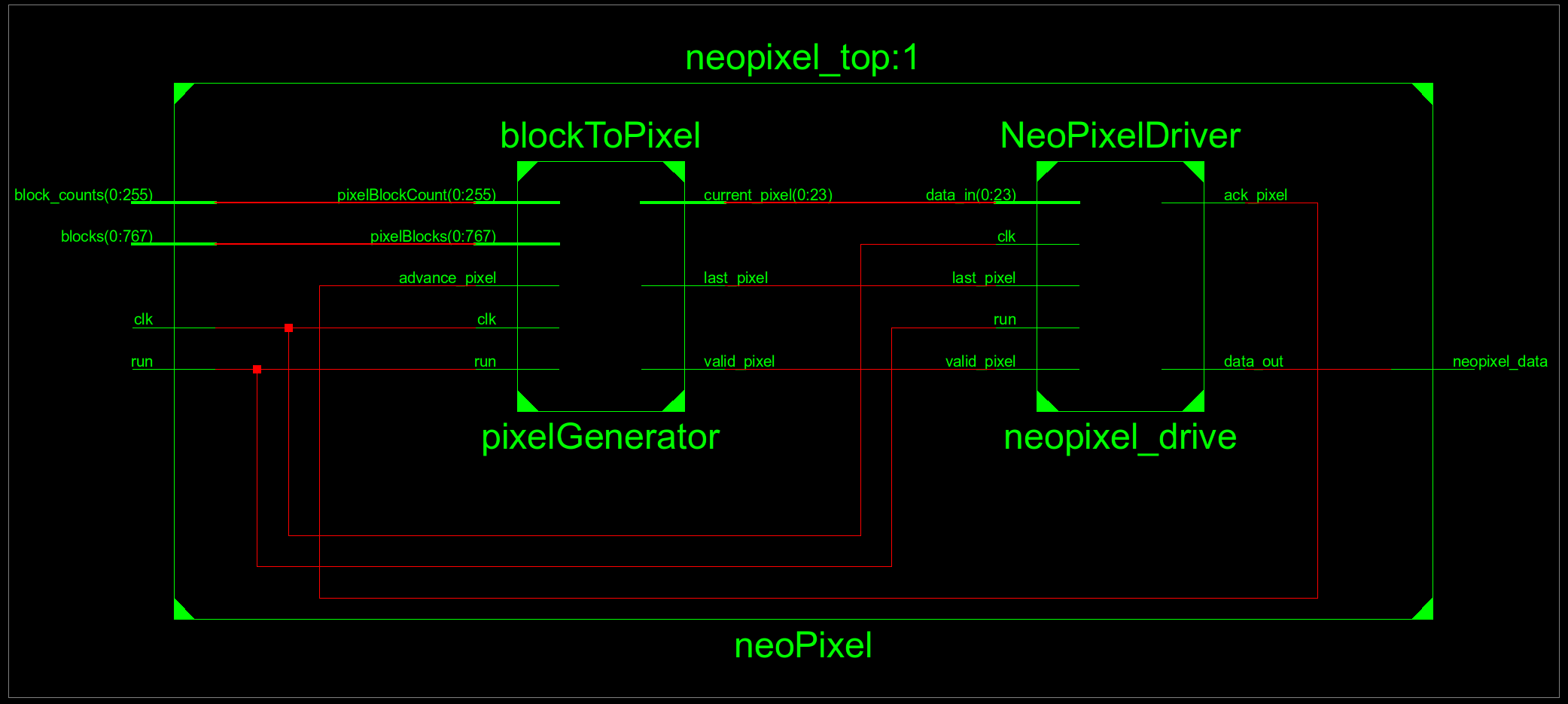
The pixel driver is split into two modules. The blockToPixel produces the values for the neopixel driver on the right. BlockToPixel takes in the color for each block and the count of each block. The neopixel driver will drive a single pixel and when the last_pxiel line goes high it will hold the data line high to tell all the LEDs to display.
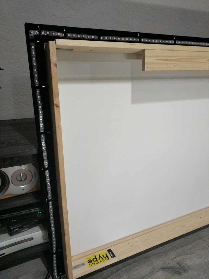
This project is currently running in my living room attached to my projector. I built a custom screen using screen material and felt tape off amazon. The screen was designed sit a few inches off the wall with a overhang for the LED Strips. This allows the LEDs to project on to the wall behind the screen providing a nice diffusion effect. The source HDMI signal comes out of my Denon Receiver, acting as a HDMI switch, goes into dinolight and then to the projector.
Add ability to control brightness check if each average if above a threshold to have black areas be dark vs dim replace all the adders with a signal adder, remove the block registers and use the memory to keep track of the current averages and each LED color. This will remove a lot of the redundant logic
