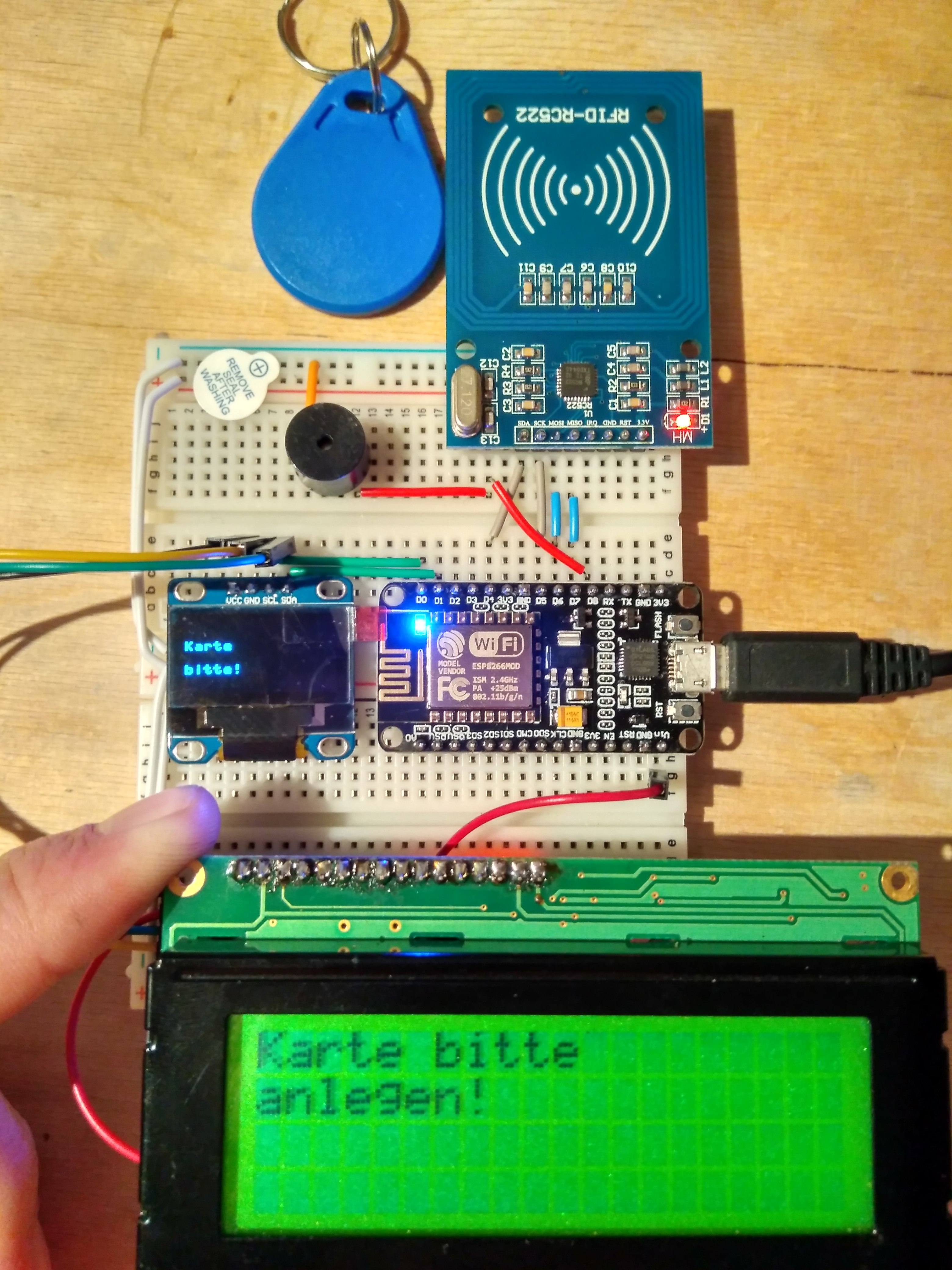
Micropython project to test the MFRC522 RFID reader and two types of display-drivers
The module mfrc522.py is for accessing the cheap RFID module via SPI-Bus. The chips are technically able to talk I2C but the board doesn't provide this funtionality be default. You have to un-solder or drill into the board to enable it. So i continued with SPI. This micropython-class to access RFID readers came from here: https://github.com/wendlers/micropython-mfrc522.
The files esp8266_i2c_lcd.py and lcd_api.py are borrowed from python_lcd and provide access to the HD77480-compatible LC-Display with an PCF8574 Backpack. On some Backpacks, an alternate chip (MCP23008) is used, but not in this project. Please make sure, you set DISPLAY_I2C_ADDR to the corresponding address of your module. I have a PCF8574A with a default address of 0x3F.
The PCF8574 has addresses 0x20 .. 0x27 The PCF8574A has addresses 0x38 .. 0x3F
Copy the folders lcd and rfid and the modules buzzer.py and main.py to the root of the flash FS on your board. You dont need to copy the wifi-folder nor the file boot.py
For the ESP8266 there are multiple solutions to do that. E.g. use the
I recommend using mpfshell or the old-school adafruit-ampy. They both work good but mpfshell is much more fun and easier to use. With mpy-utils your can mount your esp8266 to your file-system (WOW!) but you have to unmount if you need to enter the REPL (o_O). Thus its a much slower routine. I cannot recommend it.
The two files in the wifi folder are for quick ifup or ifdown of the wifi. Simple enter REPL and import them.
import wifi.wifi_up
or
import wifi.wifi_down
Do not forget to enter your SSID and Password beforehand.
I used the following pins for my setup:
| Signal | GPIO ESP8266 | GPIO NodeMCU | Note |
|---|---|---|---|
| sck | 14 | "D5" | |
| mosi | 12 | "D6" | |
| miso | 13 | "D7" | |
| rst | 4 | "D2" | You don't need the rst Pin. Try it! |
| cs | 2 | "D4" | Labeled SDA on most RFID-RC522 boards |
| scl | 5 | "D1" | This is for the I2C-Bus |
| sda | 16 | "D0" | This is for the I2C-Bus |
| buzzer | 15 | "D8" | A tiny buzzer without wave-generator |
