OpenRomSwitcher is an Open Hardware adapter PCB that allows the use of a 27xxx EPROM in place of a smaller (E)PROM. This is useful, for instance, for replacing the KERNAL and other ROMs in Commodore 16 home computers.
When installing JiffyDOS on a Commodore 16, you might want to retain the ability of switching to the original KERNAL ROM. The C16 ROM pinout is the same as a 27128 EPROM, so you can use a 27256 and put both the JiffyDOS and the original KERNAL on it. To you switch between them, you will need to either connect the A14 pin to VCC or GND.
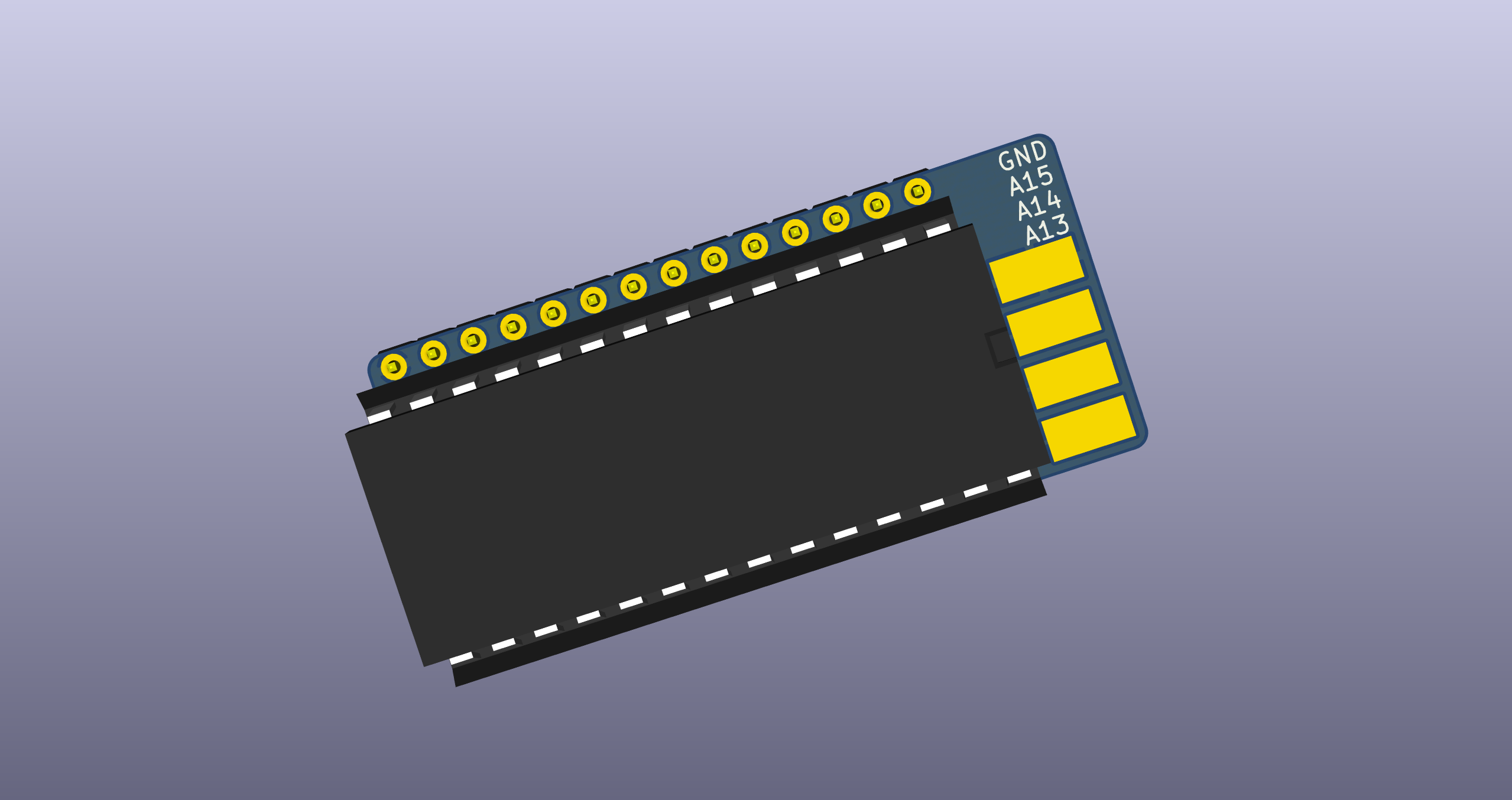
OpenRomSwitcher comes as an adapter PCB that sits inbetween the original socket and the new chip and carries the A13-A15 pins out to solder pads where switches can be wired to allow the selection of a particular ROM.
- Solder the 0805 SMD resistors first. My suggested technique is as follows: put a small blob of solder on one of the pads, then grab a resistor with tweezers, reheat the solder and slide the resistor into it, keeping it flat on the board. Hold it in place with your tweezers and take the iron away. If you didn't place it straight, reheat and correct with the tweezers. Finally solder the other end. It's not that hard, you just need to practice a few times.
- Put the pin headers into a solderless breadboard and lay the board on them, with the 0805 resistors facing down (i.e.: you should not see them). Make sure to use the two shortest hole series. Solder into place.
- Remove the board from the solderless breadboard. Using flush cutters, cut the top two pins on the right (on the soldering side) so that they are as flush to the board as possible. Repeat with the bottom two pins. Take the socket and do a test fit, it should sit flush to the board.
- Turn the board over and solder down the socket. Again, make sure it sits as flush as possible.
- You are done! Try to fit the adapter in the socket on your board or solder it down, if you prefer. In both cases, you can trim the pins shorter if you need.
Care is needed to select the proper values and placement of the resistors. You will have to choose on your own, depending on the EPROM, number of switches and exact pin connection of the original socket. Only one resistor must be soldered for each of the A13-A15 pins, either in the Switch or Straight position. This means you will ALWAYS need EXACTLY 3 resistors:
- In case you want to connect an address pin straight to the original socket, solder a 0 ohm resistor in the Straight position.
- In case you want to make an address pin switchable, solder a 10 kohm resistor to the Switch position. Note that probably any value between 5k and 50k will do.
OpenRomSwitcher has been kept as small as pratically possible, and thus it can usually be installed in the original ROM socket, with no need to desolder it.
To switch between ROMs, you will need one or more switches. Every switch must connect one of the A13-A15 pads to ground when enabled. A ground pad is available on the board, but any ground spot on the original board can be used as well, if easier to reach. Since having more than switch can be cumbersome, a rotary switch can be used as well.
IMPORTANT: ALWAYS TURN YOUR DEVICE OFF BEFORE MOVING THE ROM SELECTION SWITCH(ES).
Reconsidering the initial example of a 27256 EEPROM in the C16, I would use the following resistors:
- A13: A 0 ohm resistor in the Straight position, since C16 ROMs are 16 KB and thus the A13 line must be connected to the chip.
- A14: A 10 kohm resistor in the Switch position.
- A15: A 0 ohm resistor in the Straight position, since both 27128 and 27256 ROMs do not have an A15 pin and we can just connect that pin straight.
With this configuration a switch on the A14 pad that will allow switching between the ROMs.
OpenRomSwitcher is Open Hardware.
The following links were useful during the development of this project: