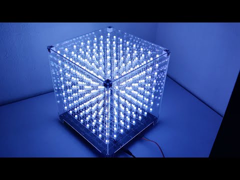
Project for controlling an 8x8x8 LED/RGB matrix cube over USB.
![]()
This project was inspired by Tomazas' firmware for controlling 8x8x8 LED Cubes, as well as Aguegu's Java program used to control the cube in real-time.
This project consists of a series of mini applets that can be used to display various animations on both Monochrome and RGB cubes.
The following are some videos of various animations in action:
There are a bunch of different styles to choose from, each animating the cube based on music being played (some are briefly shown below via the Monochrome Cube).


You can type any message into the textbox, and the cube will continuously scroll the text into view.

This will display the current time on the cube.


This will let you play the classic 'Pong Game' with a friend.

This will let you open an image and project it onto the cube.


This will let you open an image and animate it onto the cube.

This will display rain droplets.

This will display bouncing balls (optionally syncable to music being played).

- Lamp - Lights up the cube at specified times (like a nightlight).
- Lightning - Bolts of lightning travel around the cube sporatically.
- Snake - Simple snake game.
iCubeSmart 3D8-S-DIP board (Monochrome version)
The schematic for the board I used can be found here. Rather than building the PCB and all, I simply purchased a ready-to-assemble board on Amazon.
- After purchasing and assembling the board, I connected TXD, RXD, and Ground (skipping 5V until later) to the USB to TTL adapter it shipped with, and used the STC program (https://github.com/Sliicy/ledcube8x8x8/blob/master/tools/stc-isp-15xx-v6.85.zip) to flash the cube. My particular settings were as follows:
- MCU Type: STC12C5A60S2
- COM Port: Select the one that has CH340
- Min Baud Rate: 9600
- Max Baud Rate: 9600

- Press on 'Open Code File', and select the .hex or .ihx file to flash to the cube. I modified Tomazas' existing firmware to get it to work with my board, which can be downloaded here: https://github.com/Sliicy/ledcube8x8x8/blob/master/firmware/v2-sdcc-icubesmart/firmware.ihx
- Before continuing, I first clicked on 'Check MCU' just to make sure that the cube was properly being recognized. After clicking on the button, I connected 5V at this point, and then the board was recognized (MCU ID : D17EC59205195F, MCU type: STC12C5A60S2, F/W version: 7.1.4I).
- After confirming that the board was being read properly, I disconnected 5V again, and clicked on 'Download/Program', and then reconnected the 5V, to get the cube to flash the firmware.
- At this point, the cube should be flashed, and the cube should be able to talk to the program.
Since I have a slightly different cube than the aformentioned cube in Tomazas' firmware, I had to fork my own version, and modify the firmware to get it to work. Here is a link to the project (I'm using the v2-sdcc-icubesmart). Just flash the .ihx file as a regular .hex using the STC flashing tool.
iCubeSmart 3D8RGB board (RGB version)
This cube's motherboard features a separately mounted yellow board, controlled by a GD32F103RET6 microcontroller (similar to the STM32 series).
There is a YouTube video that explains the process of setting up Arduino with the STM32: https://www.youtube.com/watch?v=Myon8H111PQ
- Install Arduino IDE
- Install STM32 Cube Programmer (https://www.st.com/en/development-tools/stm32cubeprog.html). Arduino requires this installed to be able to flash to it.
- Add the following URL to Additional Board Manager URLs (File > Preferences): https://github.com/stm32duino/BoardManagerFiles/raw/main/package_stmicroelectronics_index.json
- In Tools > Boards Manager, install the latest version of STM32 (2.1.0+)
- Open the "8x8x8_RGB_LED_iCubeSmart.ino"
- Select "Generic STM32F1 series" under Tools > Board
- Select "Generic F103RETx" under Tools > Board part number
- Select "STM32CubeProgrammer (Serial)" under Tools > Upload Method
- Beneath the 8x8x8 board (on the smaller yellow board), ensure the Download switch is set to 0 (Boot1=0), and the Run switch is set to 0 (Boot0=0)
- Power the cube with both the 5V 2A cable, as well as the 4 USB cables to the USB to TTL:
- GND to GND
- TXD to TXD
- RXD to RXD
- 5V to 5V
- Jumper connecting both 3V3 and VCC
- Press Reset Button and then "Upload" in Arduino
- Toggle both switches on the yellow board so that the Download switch is set to 1 (Boot0=1) and Run switch is set to 1 (Boot1=1)
- The cube should now be ready for UART Serial Communication
- Download the latest release here (it should say something like 8x8x8.LED.Vxxx.zip). Extract the .zip file and run '8x8x8 LED.exe'.
- When opening the program the first time, head to the 2nd tab titled 'Settings', then the subsection 'Connection', and ensure the correct COM port is selected for the cube. This can be tested by disconnecting & reconnecting the cube from your PC, and watching which COM port populates.
- Make sure the appropriate cube type is selected (Monochrome or RGB).
- The Monochrome version uses a baud rate of 19,200 bps. The RGB version uses a baud rate of 2,000,000 bps. Both versions use 8 Data bits, 1 Stop bits, and no Parity.
- Next, press the 'Connect' button at the bottom of the window.
- If done correctly, there shouldn't be any error messages. You can also send a test packet in the 'Send Packet' subsection, to light up all the LEDs.
- Finally, you will want to ensure that the orientation is correct, so press the 'Calibrate Cube' button in the 'Rotation' subsection of Settings, to calibrate the cube.
- These connection settings are automatically saved. Once completed, head over to the 'Menu' tab, select an applet, open it, and enjoy!
I designed & 3D printed a custom bottom for the cube using Blender. It can be found here: https://www.thingiverse.com/thing:5236752
Anyone is welcome to provide suggestions, improvements, changes, bugs found, etc.