This page describes how to build simple but high quality syringe pumps for microfluidics applications.
This is a DropletKitchen project. Original source code of the project is provided under MIT License. The source may contain code under a different license, if this is the case it is stated in the LICENSE file.
If not stated otherwise, the designs and documentation in this repository is Copyright (c) 2016 Martin Fischlechner and DropletKitchen Contributors, and made available under a Creative Commons Attribution 4.0 International (CC BY 4.0) License.
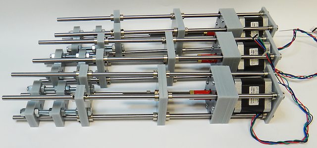
Image of the 3D-printed version of the pump.
These syringe pumps are infusion (push) only and have been designed to be as simple as possible. We are using them for droplet microfluidics and other microfluidics applications. They rival the performance of commercial-grade, high-quality pumps and are suitable for professional research.
To achieve constant flowrates without depending on an overly sturdy structure, the leadscrew itself actuates the movement of the syringe piston. This way, the pump only has to be rigid and aligned between the parts holding the nut of the leadscrew and the syringe. Different syringe diameters can be used by applying simple 3D-printed adaptors. Screws and nuts for optics assemblies are employed, which, in conjunction with microstepping the motor, result in stable flow even at very low flowrates. The pump uses it’s structural components as endstops, and the user controls the system via a software frontend based on Pure Data (Pd), a graphical programming language, which allows for straightforward and live system automation, at a small fraction of the cost of a commercial pump.
To be able to adapt the design towards other hardware, we modelled it in openSCAD (http://www.openscad.org/) in parametric form. Using the Bill of Materials, BOM, below it should work out-of-the box, else you will have to adapt the model. Please check dimensions first before laser cutting/3D printing parts. In openSCAD, the variables are defined in the header of the file, the rest of the code generating the model then works with those values. This means it is very straightforward to adapt the design towards your specific requirements. In our experience, measuring sizes with a caliper and directly putting these values into the model yields tight-fitting parts once laser-cut. With a Fused Deposition Modelling, FDM, 3D-printer you should make some test prints first (‘fit’ depends on material characteristics, print settings and the calibration of your machine). Although you can make parts fit by filing and drilling, this is cumbersome and should be avoided.
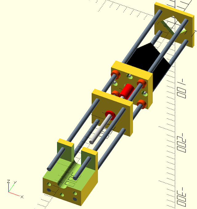
A screenshot of the pump in openSCAD (for the file see ./files/SyringePump3Dmodel.scad).
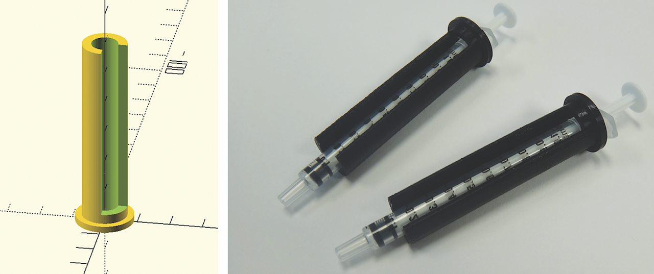
Simple 3D-printed syringe adaptors to allow the use of syringes with different diameters (see ./files/3DprintedSyringeAdaptors.scad).
- this list is for a set of 4 syringe pumps, which should be sufficient to drive most microfluidic protocols. Cost of components is approximate.
| item [4X Syringe Pumps] | number | purpose | bought from | part-no | approx (£/euro) |
|---|---|---|---|---|---|
| Allegro A4983 Based Stepper Boards: here the ‘Big Easy Driver’ | 4 | stepper board | Technobots | 2900-445 | ~ 70 |
| Nema 17 Steppers (400 steps/rev) | 4 | stepper motor | Technobots | 1402-050 | ~ 80 |
| Teensy 3.1 or 3.2 Microcontroller | 1 | control | cpc-Farnell | SC13539 | ~ 20 |
| Fine Hex Adjuster, 1/4”-80, 4” Long | 4 | leadscrew | Thorlabs | F25SS400 | ~ 40 |
| Locking Phosphor-Bronze Bushing with Nut, 1/4”-80, L=0.50” | 4 | leadscrewnut | Thorlabs | N80L6P | ~ 28 |
| Silver Steel 6mm x 333mm | 16 | pump structure | Technobots | 4426-006 | ~ 35 |
| Zinc Collets 6mm pk/4 | 24 | fasteners | Technobots | 4609-060 | ~ 28 |
| Linear Bearing LM6UU 6mm Bushing | 16 | slides motorpart | Technobots | 4604-606 | ~ 16 |
| Universal Coupling Body | 4 | motor-screw-connector | Technobots | 4604-050 | ~ 12 |
| Universal Coupling Insert - 5mm | 4 | motor-side | Technobots | 4604-059 | ~ 8 |
| Universal Coupling Insert - 1/4” | 4 | screw-side | Technobots | 4604-066 | ~ 8 |
| OTHER SMALL ITEMS | |||||
| 95mm x 127mm Copper Clad Stripboard (or bigger) | 1 | mount for electronics | Technobots | ~ 2 | |
| Male & Female PCB Headers 2.45mm pitch | some | simple connectors | cpc-Farnell | ~ 10 | |
| Sugru (good to isolate PCB-header-based connectors) | or use hotglue-gun | Maplins | ~ 7 | ||
| Screws M3 (25mm): to mount motors | 16 | Technobots | 4300-006 | ~ 3 for 100 | |
| Screws M3 (<10mm), optional | many | fix collets better | Technobots | 4300-002 | ~ 2 for 100 |
| Screws M6 (~100mm), syringe part lasercut version | 8 | reduces acrylic | hardware shop | ||
| USB (micro) cable | 1 | cpc-Farnell | ~ 3 | ||
| 6 wire colored ribbon cable | 4m | Technobots | ~ 3 | ||
| 12V/>=5A power supply | 1 | cpc-farnell | ~ 20 | ||
| 3D-printer filament (PLA) or 5mm acrylic sheets(410X280) | 1kg/5sheets | pump structure | RS, Techsoft | ~ 30 | |
| 4 pumps: | ~ 425 |
- Technobots: http://www.technobotsonline.com
- Thorlabs: http:/www.thorlabs.com
- CPC-Farnell: http://cpc.farnell.com/
- RS: http://uk.rs-online.com/web/
- Techsoft: http://www.techsoft.co.uk/
- Maplin: http://www.maplin.co.uk
All components but the optics-screws (Thorlabs) can be obtained commercially. If other leadscrews are used, the software has to be adapted to the distance/revolution grading.
- Lasercutter (we used an Epilog, 30W): Often found in a local hackerspace or University Engineering Department. One could also use internet-based services.
- FDM 3D-printer (we use an Ultimaker 2 & PLA (natural white) material)
- Soldering iron
- Hand tools (screwdrivers etc.)
- adapt the openSCAD model to your needs by changing the variables as you see fit and rendering the model.
- export .stl-files of all the parts (syringe-part, leadscrew-part, motor-part, end-part). It is easiest to comment-out all parts but one, render and export to .stl.
- import the .stl files into openSCAD, orient them so that the
projection you want is at (0,0,0). Render and export as .dxf-file,
which can then be directly used by a laser cutter.
projection(cut=true)
translate ([0, 0, 0])
rotate ([0,0,0])
import("/pathtofile/file.stl");
// comment projection out first, adjust translate/rotate (slices at 0,0,0),
// uncomment projection(cut=true),render, export to .dxf
- cut out all the parts. It might be a good idea to check dimensions and fit first by cutting a trial sample.
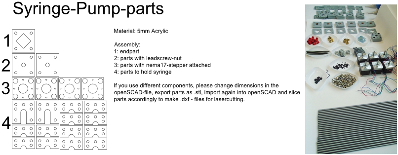
- if you use the components from above, you should be able to use the .dxf-file provided (./files/PumpPartsLaserCut.dxf; see below). To work with 2D-CAD files we use the free version of Draftsight (http://www.3ds.com/products-services/draftsight-cad-software/free-download/).
Left: Laser cut parts for one pump. Right: Image of components.
- tin the leads of the motors with solder, add a male PCB-connector (or any other connector of your choosing. On our motors the colored leads are GREEN, BLACK, BLUE, RED).
- we use Sugru to electrically isolate the connectors at the end.
- add the connector for the leadscrew (5mm brass insert) to the motor - you might not have space to do that later.
- depending which length of M3 screws you have used to mount the motor, you will need different quantities of acrylic sheets. LM6UU bearings are 19mm in length, so 4X5mm sheets are fine. If you have longer screws, either add nuts or fit in some more acrylic sheets.
- slot the 4 bearings into the stack of parts (should be lightly press-fit); screw the assembly together. The bearings do not have to bear much load. If they aren’t fixed well enough use a dab of epoxy glue.
- take the two acrylic sheets and mount the leadscrew-nut.
- add the brass insert to connect the motor onto the leadscrew
- insert the screw VERY carefully to avoid damaging the thread which can happen rather easily.
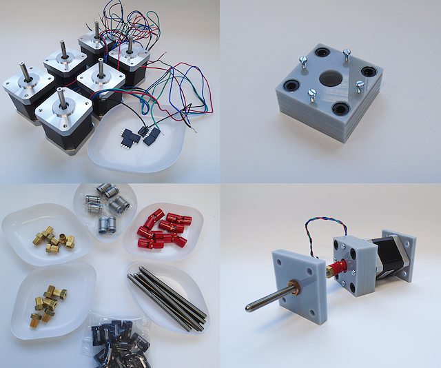
Pre-assemble motor with leadscrew (bottom right) and component inventory.
For this part one should design towards specific needs. Make sure the cutouts are big enough for your syringes. If you want to use different syringes with different diameters, adjust the CAD-model to the thickest diameter and 3D-print/laser cut adaptors that can be quickly exchanged.The adaptors must allow the piston of the syringe to reside exactly in the centerline of the screw.
You can either cut many slides and assemble as a stack, or use some long M6 screws and attach pairs of parts with M6 nuts. If you use tape to hold the syringes in place (which works fine), filling the structure with acrylic plates provides a continuous surface for fixing the tape in place.
- take 4 of the 6mm steel shafts, round off the edges with a file to ease assembly.
- slot the steel shafts into the assembled motor part. Take care not to harm the LM6UU linear bearings.
- add endpart, leadscrew-part and syringe part. Do not forget to insert the collets (8 collets/part, before and after). Don’t fix them yet.
- measure the length of the syringes you want to use. There is no electronic endstops put into the design to keep assembly-time to a minimum (although it could be done rather easily). To make sure that your (glass) syringes stay unharmed, the length between the syringe- and the leadscrew part should be adjusted such that the movement will be blocked mechanically before crushing the syringe. The endpart should be mounted such that the movement will be blocked before the leadscrew turns itself out of its nut. If the motor hits these points it will stall, making a different noise than usual, but else stay unharmed. Don’t forget to adjust the power of the motor on the respective potentiometer on the stepper driver board. With maximal power applied, the stepper motor can damage the assembly.
Three pumps before adjusting the leadscrew part & fixing everything with collets.
- fix the collets of the syringe part. In general it is a good idea to use short M3-screws instead of the small hex-screws provided for making repeated opening/closing easier.
- add the electronics to the motor and drive it back and forth (at this point you could add some lithium grease or other lubricant). The leadscrew-part has to be adjusted such that the turning leadscrew stays centered without wobble. Use your syringes to adjust the length between leadscrew and syringe part. This serves as a mechanical endstop for forward movement. Handle the position of the endpart accordingly to stop backward motion. Then fix the collets securely.
- when finished use a bit of epoxy glue to permanently connect the ‘universal coupling body’ with the brass inserts. The assembly can still be taken apart by loosening the grub-screws holding the motor shaft and the leadscrew together.
- done!
Depending on the calibration of your FDM-printer, parts might need some ‘adjustments’. Please print calibration pieces first to make sure the parts are well fitting. If needed, you can use a drill-bit or a round file to make adjustments but it is not much fun. Assembly of pumps is similar to the lasercut version. To generate the .stl-files for printing, it is easiest to comment out all parts but one in the openSCAD model, render and export.
Two modified 3D-printed pumps with smaller, lower power Nema14 motors used in a microfluidic experiment. The electronics in the image is based on a ‘Quadstepper board’ (unfortunately no longer available).
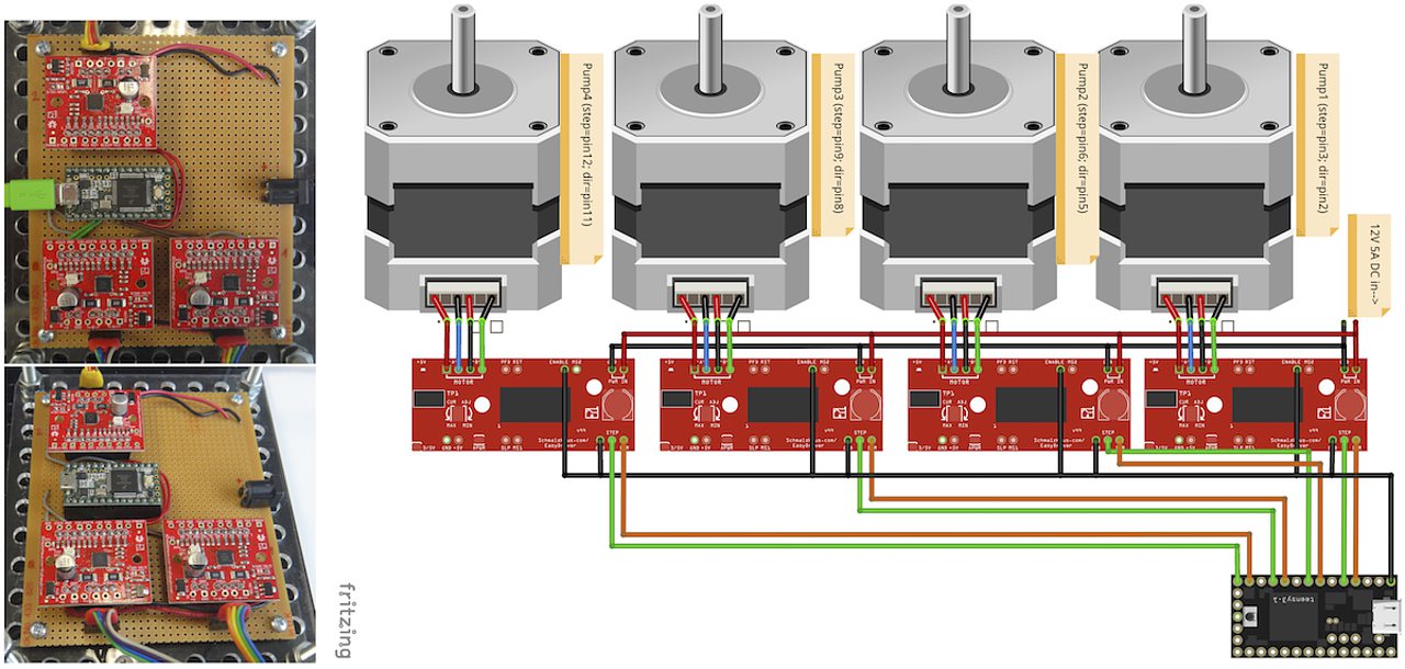
To drive the stepper motors of the pumps we use a A4983 stepper driver chip from Allegro Microsystems (datasheet http://www.technobotsonline.com/Datasheets2/1518-009-A4983SETTR-T.pdf). For convenience we use one ‘Big Easy Driver’ for each motor (http://www.technobotsonline.com/big-easy-driver.html, http://www.schmalzhaus.com/BigEasyDriver/). The ‘Big Easy Driver’ boards are nice, because they default to 16 step microstepping mode, when the ‘MS1, MS2, MS3’ pins are left unconnected (which means that less soldering has to be done). With 16-step microstepping, one revelation of the leadscrew (318 micrometer movement) is divided into 400*16=6400 steps resulting in a stable flow even at very low flowrates. If you use a stepper with 200 steps/revolution (1.8 instead of 0.9 degrees/step), the pumps will still work very well but you will have to adjust the calibration in the software. If you are prepared for some more soldering, any stepper driver board used in common FDM 3D-printers should do just fine. The stepper drivers are controlled with a teensy 3.1 or 3.2 microcontroller. The teensy has 3.3V logic levels, so put a solder-blob onto the stepper drivers to switch them from 5V (default) to 3V logic.
Left: Images of the electronics board with three stepper driver boards mounted. Right: Schematic diagram.
- solder connectors onto the driver board (e.g. PCB-connectors)
- layout the parts on a stripboard and drill holes so that you can mount the board with screws to an enclosure (e.g. from laser-cut acrylic).
- solder female PCB-connectors on the board for the teensy and the stepper boards (don’t forget to cut the traces on the stripboard underneath).
- make all the necessary connections (see layout…)
- we made the system as simple as possible:
- no connection to MS1, MS2, MS3 - all are pulled high when not connected (means the driver defaults to 16 microstep-mode
- no connection to sleep (slp) and reset (rst) - if powered the system will be on all the time. If you want to shut down the motors, turn off the power.
- this leaves only the following connections to be made:
- enable (en) is pulled low on all by connecting to ground (this is important, else the pins float).
- shared GND between teensy and the quadstepper board (or single big easy drivers)
- step-pin (stp): if high for >1 microsecond, the motor will step
- direction-pin (dir): high/low sets the direction (if your pump steps the ‘wrong’ direction, just reverse the connections of the leads from (e.g. green, black, blue, red –> to red, blue, black, green).
- Teensy is powered by a USB connection and the motors are powered separately (we use a 12V 5A power supply).
- Don’t forget to adjust the current supplied to the motor with the small potentiometer on the stepper driver board. On max, the chip gets hot and the motor might have enough torque to continue beyond the end-stop, damaging the pump assembly.
The pumps are controlled with a microcontroller (a ‘teensy’ 3.2 or 3.1) and a software front end written in Pure Data (PD). The teensy (https://www.pjrc.com/teensy/teensy31.html) is a 3.3V, 32-bit ARM based microcontroller that is compatible with the Arduino toolchain (https://www.arduino.cc/en/Guide/HomePage) and therefore easy to program. The prime reason to use a teensy is the high speed USB data transfer they allow (https://www.pjrc.com/teensy/benchmark_usb_serial_receive.html). Apart from controlling machinery, the teensy is well suited for data acquisition tasks.
Pure Data (PD, https://puredata.info/) is an open source dataflow programming language used primarily for music and video applications. It runs on nearly every computing platform, is straightforward to learn and can be modified ‘live’, which is great for microfluidics experimentation.
The communication protocol between the microcontroller and PD is OSC (‘Open Sound Control’, https://www.opensoundcontrol.org). It is a very flexible, easy to use two-way communication.
System diagram.
The easiest way to program teensy microcontrollers is to use the Arduino IDE (download:https://www.arduino.cc/en/Main/Software). For the teensy microcontrollers to be recognised by the Arduino IDE, one must additionally install ‘Teensyduino’ (download: https://www.pjrc.com/teensy/td_download.html). There is a detailed tutorial on software installation and its use on the webpage. Most of the Arduino libraries are compatible with teensy, Teensyduino itself comes with many optimized ones (full install recommended).
Pure Data can be downloaded from the PD community site (https://puredata.info/downloads) and installation is straightforward.
For Mac or Win you should choose to install PD-extended, which is pre-packaged with many additional externals from the community (all necessary things needed for this project should be installed per default). PD-extended is not actively maintained any more, but still works well. Alternatively you can use PD-Vanilla and install externals via the ‘deken’-plugin (https://github.com/pure-data/deken) as required.
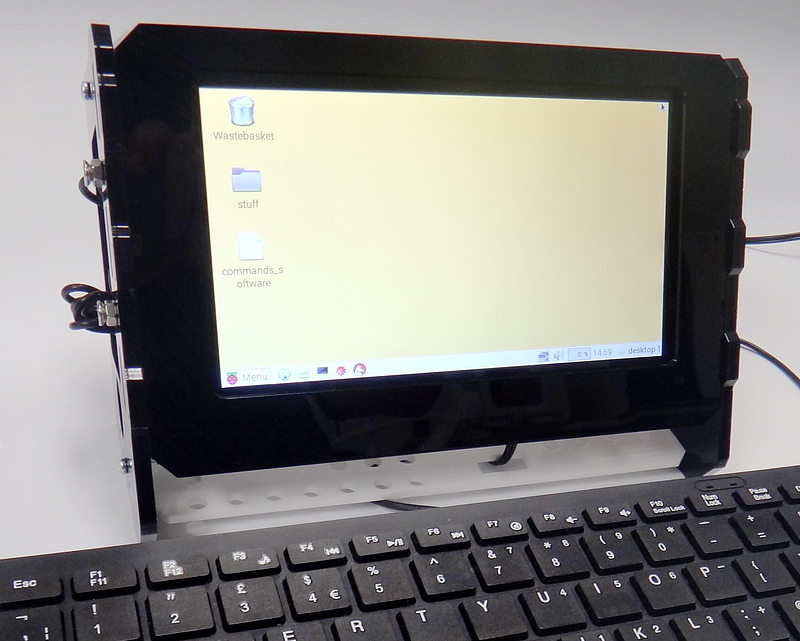
On a Linux system, you should use ‘PD-L2ORK’ (http://l2ork.music.vt.edu/main/make-your-own-l2ork/software/), an up-to-date, maintained and beautified version of PD-extended from the ‘Linux Laptop Orchestra’ (Virginia Tech Music Department). Beta versions for Mac and Win are now also available. PD-L2ORK runs well on Ubuntu, but also under Raspbian on Raspberry Pi Model 2 and 3. This allows a small touchscreen interface to be used resulting in a small-footprint solution.
Raspberry Pi Model 3 used to control syringe pumps. The files for the lasercut enclosure are based on a design by Sparkovsky on Thingiverse (https://www.thingiverse.com/thing:1441432).
- program the teensy
- open the PD-program
- and you should (almost) be ready to go.
You can test the system without the microcontroller attached to the pumps. If the communication works via OSC, the flow rates you transfer (in microL/h) and the direction of movement will be mirrored in the smaller sliders beneath the main control elements in the PD-frontend.
In a nutshell, the desired flowrate (in uL/h) is converted into a delay time (in microseconds) which defines when the motor on the pump has to step. To make this delay time as precise as possible, an interrupt routine is used that checks every 10 microseconds if a motor has to be stepped or not - no matter what the rest of the program is doing at that time. Flow rate to delay time conversion is dependent on the type of motor (steps/rev), thread-type of the leadscrew used (microns/revolution) and syringe diameter.
We supply two versions of the programs here that differ where these calculations take place:
- ‘Hardcoded’: directly on the microcontroller (PD transfers the flow rate value, the syringe diameter and other values are to be changed in the program running on the teensy). This is convenient if one always works with syringes of a certain diameter.
- ‘Flexible’: all calculations are done in PD and the resulting delay times in microseconds are transferred. This allows all parameters in PD to be changed on the fly without reprogramming the microcontroller when changing hardware.
- upload the corresponding file to the microcontroller (./files/Hardcoded4Pumps.ino). Have a look at the code, everything you can and might have to change should be explained in the comments.
- place the PD-program (./files/Hardcoded4Pumps.pd) together with a little helper-program for OSC (./files/o.io.slipserial.pd) in a folder and open it in PD-extended or PD-L2ORK.
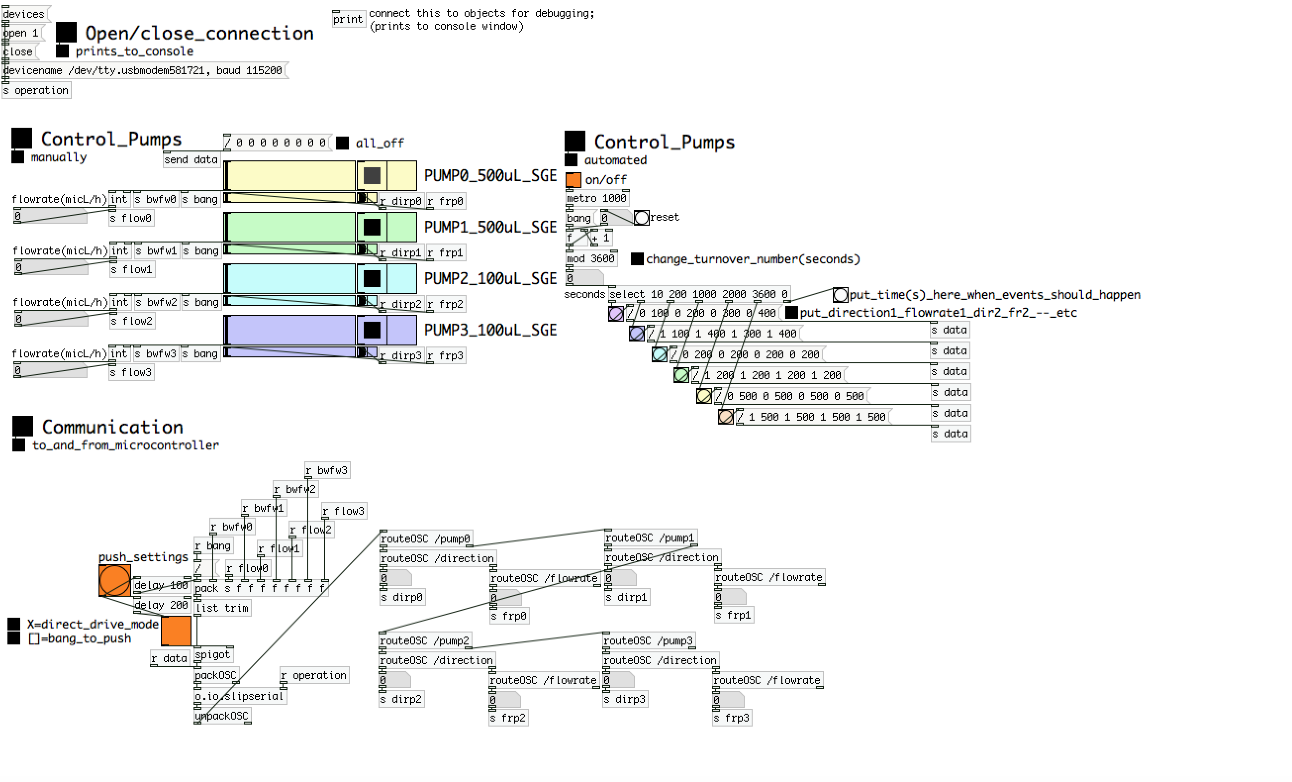
Screenshot of the program.
- Hit [devices], and the available serial ports will show in the console window. One of them is connected to the teensy. Click [open x[ (change the numbers by entering editing mode, ctrl-e (linux), cmd-e (mac)) and PD should connect to the teensy.
- The section ‘Control Pumps Manually’ allows you to dial in your desired flow rate for each pump. The buttons on the right side of the sliders will change direction. If you right-click on an item/box a properties and help dialog is available which lets you learn and customize. If the values are transferred to the teensy, the microcontroller will send the list of numbers back. Those are displayed underneath and give immediate visual feedback. If you have the pumps connected and powered, you should see the changes there too.
- To transfer the pump settings, you have to click the orange ‘bang’ in ‘Communication to and from microcontroller’. For immediate response when changing settings, click the orange toggle switch to mark it [X].
- ‘Control Pumps Automated’ is a simple tool for automation. Setting the toggle-switch to ‘on’ [X] activates a counter (per default here in seconds) which will turnover to 0 after some time (here 1h). The [select] box activates the attached lists of numbers (direction pump1 flowrate pump1 ....) after the dialled-in times. To change it, get into edit-mode, change the values and the numbers of events to your liking (you will have to copy/paste/delete structures and reconnect).
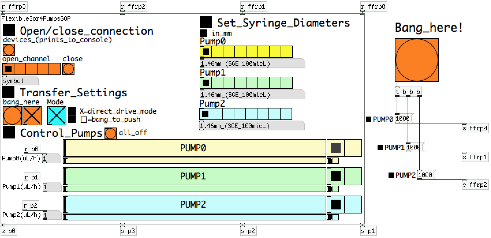
This version of the programme is reduced in its footprint to be displayed on a 7” screen (in our case a raspberry Pi Model 3 with a touchscreen). It uses PD’s ‘Graph on Parent (GOP)’ feature which allows program complexity to be hidden. It is used similarly as above, but lets you select serial ports as well as syringe diameters. The right-hand part outside the ‘GOP’ can be modified for more complex automation.
Screenshot of the program.
- upload the corresponding file to the microcontroller (./files/Flexible3or4Pumps.ino).
- place the PD-programs (./files/Flexible3or4Pumps.pd) and (./files/Flexible3or4PumpsGOP.pd) together with a little helper-program for OSC (./files/o.io.slipserial.pd) in a folder and open it in PD-extended or PD-L2ORK.
- The file ‘Flexible3or4Pumps.pd’ is the software front end. If you want to change the program in any way, changes have to be conducted in ‘Flexible3or4PumpsGOP.pd’. The program actually contains controls for 4 pumps, but only 3 are shown in the front end. To have a 4-pump system, enlarge the red ‘GOP’ rectangle and move the controls for the 4th pump into the space. It will then show in the front end. The calculations in ‘Flexible3or4PumpsGOP.pd’ should be simple to adapt to modified hardware.

