Important

SIMULTANEOUSLY :
- Multiple inverters.
(PIPsolar/Voltronic, Deye, Growatt, Sofar, Victron, etc...) - And multiple BMS.
(JKBMS, AntBMS, DalyBMS, SeplosBMS, Pylontech, etc...)
-> In theory any inverter or BMS with ESPhome support can be used with the PVbrain2.
It also adds the possibility of controlling up to 32 relays allowing for example to control an Automatic Transfer Switch (ATS) (Offgrid<=>return to the network).
The PCB uses only crossover components or pluggable components in order to have easy setup/maintenance.
The MCU used is an ESP32S3 running 

-> But 
The main features are :
- Direct communication and control with Voltronic/Pipsolar, DEYE, SOFAR, GROWATT inverters via direct Ethernet cable.
(pvbrain has a built-in RS232 and RS485 => TTL) - CANbus support. Possibility to translate informations from old generation BMS into modern CANbus protocols (Pylontech 1.2, Pylontech +, SMA, Victron)
- The VEdirect for
models with an insulated adapter provided.
- Important settings can be set directly from HA (or the web server if enabled).
- Monitor multiple BMS (tested with JKBMS but should work with antBMS, DalyBMS PaceBMS or SeplosBMS) with an insulated adapter provided.
- Detect multiple AC sources (solar/network/other) (in order for example to do soft switching for the ATS part).
- Monitor via a JSY193, JSY194T module (modbus) solar and network production.
- Control up to 32x relays with two i2c extension SX1509, that is for ATS control or the reversing mode of a modern inverter.
(Axpert max I & II for example) - The solar power diverter thanks to ROBOTDYN or SSR modules controlled in PWM.
- Monitor your basement temperature/humidity/pressure with BME280 (you can set up alarms just in case).
- Free I2C ports available for plugging in additional I2C sensors.
- SPI port is also available.
Note
This PCB uses the excellent ESPhome integrations done by :
The PVbrain 2.0 represents a joint work between 


For more information on the project, the pcb, the code and their use, please refer to the wiki.
- First of all be sure you have installed on your machine the ESP32 S3 driver from Sillicon Labs.
Classic procedure :
Click here for show the Classic procedure.
⤵️ 🔙
- 1️⃣ ➖ Retrieve the PVbrain 2.0 zip (by right clicking) and save it into a new created folder, eg. /pvbrain2
- 2️⃣ ➖ Uncompress the zip file into your local folder (/pvbrain2) or into your/config/esphome folder of HASSIO (use samba share to transfer the uncompressed files).
- 3️⃣ ➖ Open your esphome's secrets.yaml file and check if wifi_ssid, wifi_password and ap_password variables are correctly corresponding with your local WiFi informations.
- 4️⃣ ➖ Edit the PVbrain2.yaml and comment/uncomment each package according to your own solar setup.
- 5️⃣ ➖ Compile and upload the code on your ESP32 S3 device.
Dummy procedure (for newbabies) :
Click here for show the Dummy procedure.
⤵️ 🔙
- 1️⃣ ➖ Create/sign in a Github accompt. You can create it faster with OAuth2 via your google account for example.
- 2️⃣ ➖ Open the following Gitpod link.
- The first time you will need also to sign in into gitpod framework for example with your previously created Github account.
- 3️⃣ ➖ When logged into Gitpod, you will see during the ESPhome installation, some log lines printed in the terminal.
- Wait a couples of minutes to let finish the processus.
- When done, press the "Open Browser" located at the botton right of the Gitpod page.
- It should open a new webpage with the ESPhome Dashboard.
- 4️⃣ ➖ On the ESPhome Dashboard, click first on "secret" button located at the top right corner.
- Replace "xxxxxxxx", "yyyyyyyy" and "zzzzzzzz" with your own WiFi SSID/password and AP informations (AP password will allow to access to your PVbrain2 if your WiFi/LAN is down).
- Be aware, WiFi password must be a minimum of 8 caractars.
- If not, you will need to change your WiFi password correspondly.
- Click on "save" and quit the secret page by clicking on the top left cross.
- 5️⃣ ➖ Click on "Edit" for the PVbrain2 model.
- Comment and/or uncomment each package according to your own solar setup and save the file. (Tip: you can comment/uncomment several lines simultaneously by selecting the lines and press on CTRL + /)
- 6️⃣ ➖ Plug your ESP32-S3 with a USB data cable first then the on top right corner, choose "Install" then on "Plug into this computer" to compile the firmware. It can be a long processus !!!.
- Wait a couple of minutes (it first compile the code at background during 3-4min) then it starts the flashing part.
- You should see a progression bar running when flashing.
- 7️⃣ ➖ You finished the flashing procedure.
- If you entered correctly your WiFi informations in the secrets.yaml file, you should see a notification in Home Assistant asking you to accept a new ESPhome device.
- Accept it... You finished!!!!
| 3D View | Copper Area |
|---|---|
 |
 |
Please find all Gerber files required for the PCB in the following folder : Hardware.
Also, find all BOM (Aliexpress and Amzon links) and some extra information in this 
Special clip-on modules were created by 
Module to extend the number of uarts on an esp32 (4 Uarts per card) an 8 GPIO, possibility of communicating in I2C or SPI.
| 3D View | Schematic |
|---|---|
 |
 |
Before discovering the WK2168 module which allowed the creation of the card above, a DIY version of the DFRobot DFR0627 had been designed.
Its cost is a little lower than its big brother the WK2168, but it only allows 2 additional UARTs.
| 3D View | Schematic |
|---|---|
 |
 |
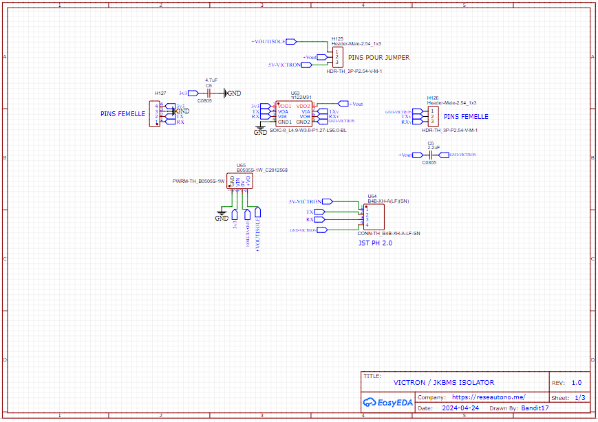
TTL isolator, originally designed for Victron VEdirect.
| 3D View | Schematic |
|---|---|
 |
 |
Simple Shunt for Direct UART output.
| Front | 3D View |
|---|---|
 |
 |
An optional addon card can be plugged to allowing 4 additional UART outputs.
| 3D View | Schematic |
|---|---|
 |
 |
Click here for show other views. ⤵️
🔙
| Front | Back | Circuit |
|---|---|---|
 |
 |
 |
Also, find all BOM (Aliexpress and Amzon links) and some extra information in this 
An optional addon card can be plugged to allowing 4 additional CAN MODULE SPI.
| 3D View |
|---|
Click here for show other views. ⤵️
🔙
| Front | Back |
|---|---|
Also, find all BOM (Aliexpress and Amzon links) and some extra information in this 
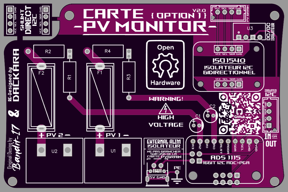
Addon card created for PVbrain V1 by 

The card offers the possibility of securely monitoring the voltage of two DC inputs.
| 3D View | Schematic |
|---|---|
 |
 |
Click here for show other views. ⤵️
🔙
| Front | Back | Circuit |
|---|---|---|
 |
 |
 |
Also, find all BOM (Aliexpress and Amzon links) and some extra information in this 
An additional card was created by 
| 3D View | Photography |
|---|---|
 |
 |
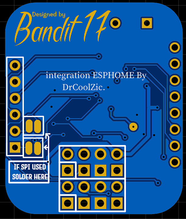
Another option card created by 
- 1 to 16 Clamp (2 mounting possible for each output : JST-XH for 2-strand clamp or Jack for SCT013)
- 1 to 4 pre-addressed ADS1115.
- 1 TCA9548A (optional - bridging if not used) to multiplex the I2C (useful in the event of more than 4 ADS or I2C address conflict) with all its outputs remote for external use.
- 1 ESP possible at input for non-PVbrain users or other reasons... 6 assembly possible: (offset of all outputs and recovery of i2c via bridging).
| ESP8266 D1 Mini | ESP32 D1 Mini | ESP32 S2 Mini | ESP32 C3 | ESP32 C3 Zero | ESP32 S3 Zero |
|---|
Link to the Github Page: 
| 3D View | Circuit |
|---|---|
 |
 |
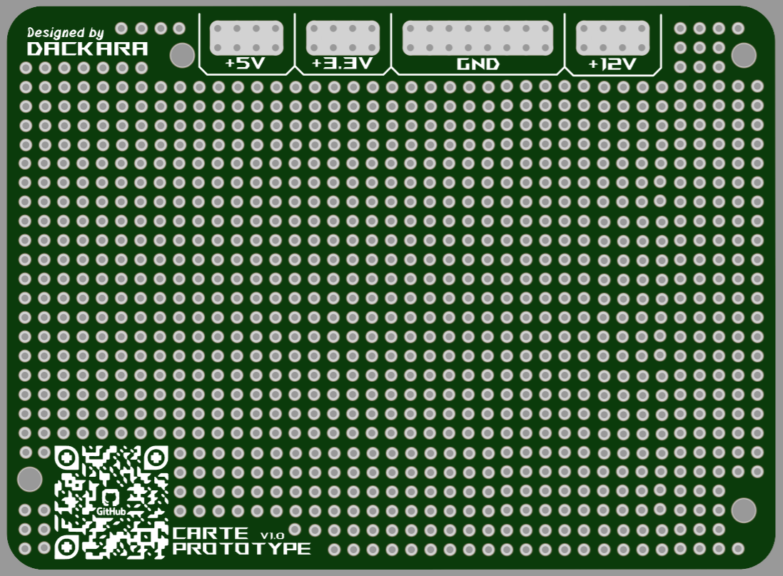
Just a prototyping board with the same footprint as the other addon boards.
| Front |
|---|
 |
3D Files to print, created by 
A plastic card in the same format as the addon cards which can, for example, allow circuit isolation, is also available.
| Front View | Back View |
|---|---|
 |
 |
The old "Option 2" card made by 
| 3D View |
|---|
 |


