USB Type C charger for laptops or phones, that uses generic DC inputs as the source.
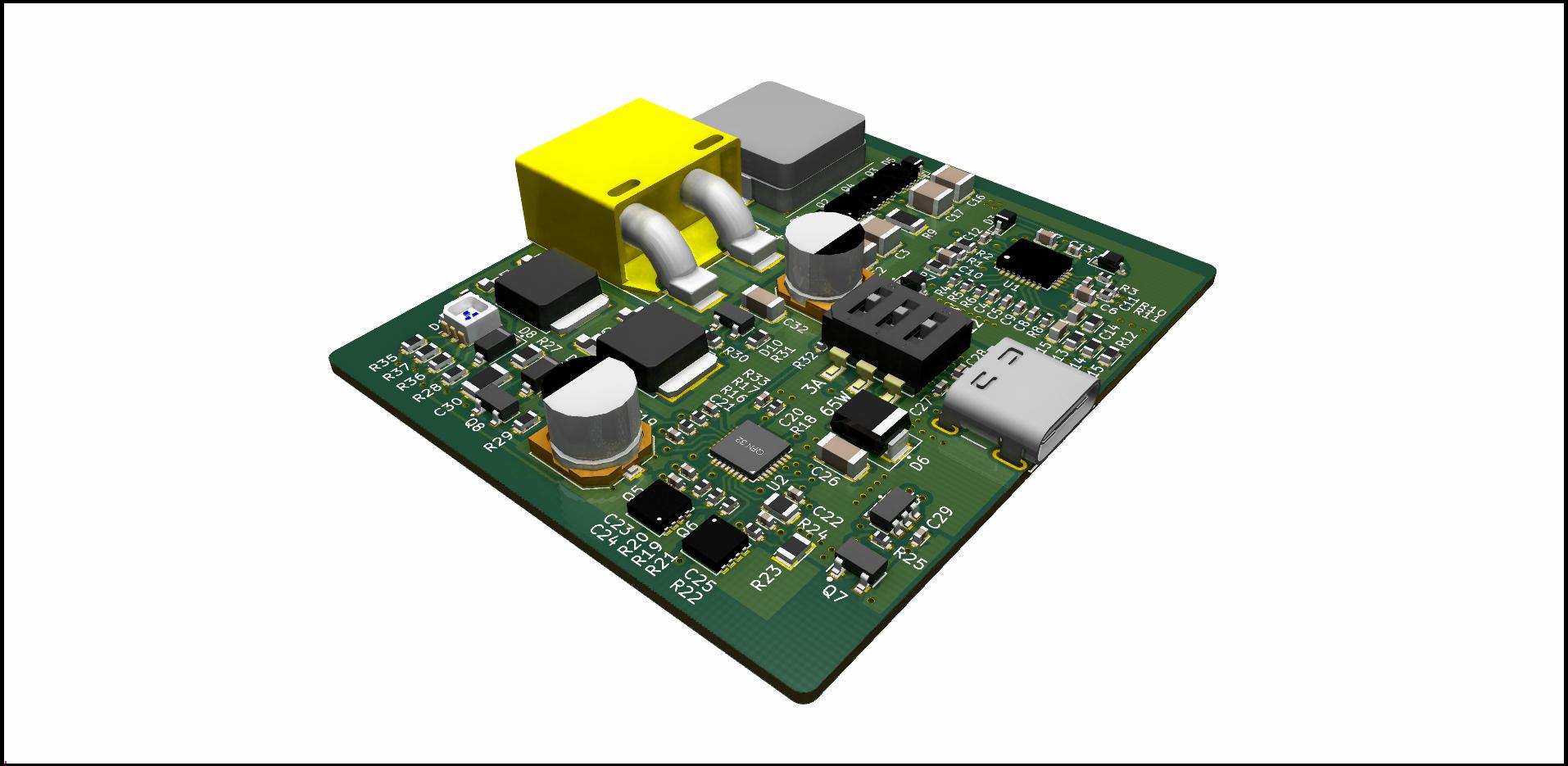
Create a DC-DC charger that uses USBc PD as the delivery mechanism. Aim to support the widest range of devices possible (including my Dell XPS 9550).
Run off Li-Poly or Li-Ion cells or similar sources. This could include car batteries (directly or from cigarette lighter socket), and other sources. This is useful when taking devices to the field, or allows a comodity pouch cell battery to act as a bulk battery bank.
-
Accept wide input range sources, 10V to 26V operating input (3S to 6S lithium, includes 12V and 24V automotive).
-
Use XT60? input to allow direct lipo connectors or existing COTS cables with aligators etc.
-
Input must be ESD protected and filtered.
-
Input must have reverse polarity protection, and overvoltage up to 30V DC.
-
Device must indicate that a power source has been applied.
-
Device should include visual indication that battery is low.
-
Device should include battery voltage low-cutoff to prevent over-discharge of source.
-
Output USB 3.1 C Power Delivery 2.0 Compliant charging power (5, 9, 12, 20V) at up to 3A. Consider 5A as optional expansion?
-
USB Type C socket on the charger, to allow users to find their own cable. No integrated cable tail.
-
Compatibility with Dell XPS, Apple Macbook Pro, and other devices.
-
Compatibility with USB-C fast charging phones if possible.
-
Compatiblity with USB2 charging devices as part of compatibility mode (via 3.1C -> 2.0 MicroB cable).
-
It is desirable that the charger supports greater than 60W charging for faster charge on performance laptops.
-
Output should be ESD Protected and feature filtering for EMI.
-
Where practical, x/y/z dimensions should be minimised for tight form factor.
-
The device's enclosure should not exceed 50C at steadystate for a 'full load'.
-
The device should not emit any audible noice (coil whine etc) which can be heard in a quite space (<25dB?)
-
The product should aim to meet applicable EMC standards (class 2, non-intentional radiator), use spec analyser at work to validate.
Ideally this solution costs less than $100AU (not including charge cable or batteries). This would price it under or around the Apple 61W and 87W chargers, or the Chromebook Pixel 60W charger after importing to AUS.
- Manufacturing cost of assembled PCB is less than $60USD.
- Manufacturing cost of enclosure less than $20USD.
- Manufacturing cost of packaging (box, manual, etc) less than $5USD.
- Wide input power supply low voltage cutoff set at just under 9V. This is the extent of low battery protection, not using anything smarter.
- Currently there is no additional 3 or 5V reg, which means there isn't any stable voltage. Any additional circuitry has to either support 5-20V or include regulation.
- Input protection circuit is beefy. Confidence in the charger is important, especially with all the press going on with USBC non-compliant chargers.
- Battery indication led was really hard to get worked out. Uses a SMD led and lightpipe for charging status. Might remove this for production.
- Board has been made as small as possible to fit in the example extrusion.
- Power dissipation for power supply stage is worst case 1.7W between all parts. Worst part is switching fet at 650mW. Consider heatsink or thermal transfer to case?
- Validate thermal performance with thermal camera.
- XT60 connector is too high for normal mounting. Consider using a second PCB to drop the height to the center of the extrusion or a different connector.
- Greater than 3A is supported with switch.
- Power limit set to ~60W default, switch will allow ~90W.
- 5A is possible to be selected without the 90W expansion (5/12V devices)
- Board is a 4 layer pcb with single sided population. All parts are SMD.
- Small form factor means small boxes and packaging requirements.
- Consider enclosures
- https://www.aliexpress.com/store/product/4-pcs-electronics-aluminum-enclosure-boxes-13-60-50mm-2015-aluminum-powder-coating-project-box-aluminum/1006252_32312473247.html?spm=2114.12010612.0.0.7DTtvx
- https://www.aliexpress.com/item/1-piece-szomk-aluminum-project-box-100-60-13mm-enclosures-for-electronics-electronic-2014-new-aluminum/32241037210.html
5 Prototype boards have been ordered for PCBA. Cost per board is just under 60USD at current.
-
Dell XPS didn't like negotiation stage where eval board sat at 12V for a few hundred milliseconds. Disabling 12V and going from 5->20V works fine.
-
Investigate XPS when the 5V and 20V are done by same regulator instead of two-stage.
-
Dell XPS will charge on lower currents as long as the charger is advertising at least 60W.
-
Haven't been able to get more than 61W draw from the XPS, regardless of BIOS settings.
-
Nintendo Switch uses the 15V standard which the main model of this charger is not designed for.
-
The Switch will charge with 5V 3A though.
-
People in https://www.reddit.com/r/NintendoSwitch/comments/5x948s/answering_your_questions_about_usb_typec/ say that the Switch uses 12V as fallback from 15V.
-
Supports BC1.2 charging for legacy USB2 devices at up to 2A.
-
Charges phones fine at 10W over a USBC-MicroB cable.
-
Should support most phones properly with 5V 3A charging over TypeC.
Sell it as a standalone device with the option of adding the following:
- Barrel to XT60 connector
- Barrel to Aligator clips
- Barrel to cigarette lighter
- Barrel to D-Tap
- Barrel to ring terminals?
Device should also include some packaging and a card describing the specifications etc.