This repository contains all the code for the final project of Udacity Self Driving Car Nanodegree: Programming a Real Self Driving Car.
In this project the goal is to write ROS nodes to implement core functionality of the autonomous vehicle system, including traffic light detection, control, and waypoint following.
The code is developed in simulator and then tested on Carla, Udacity's self driving car.
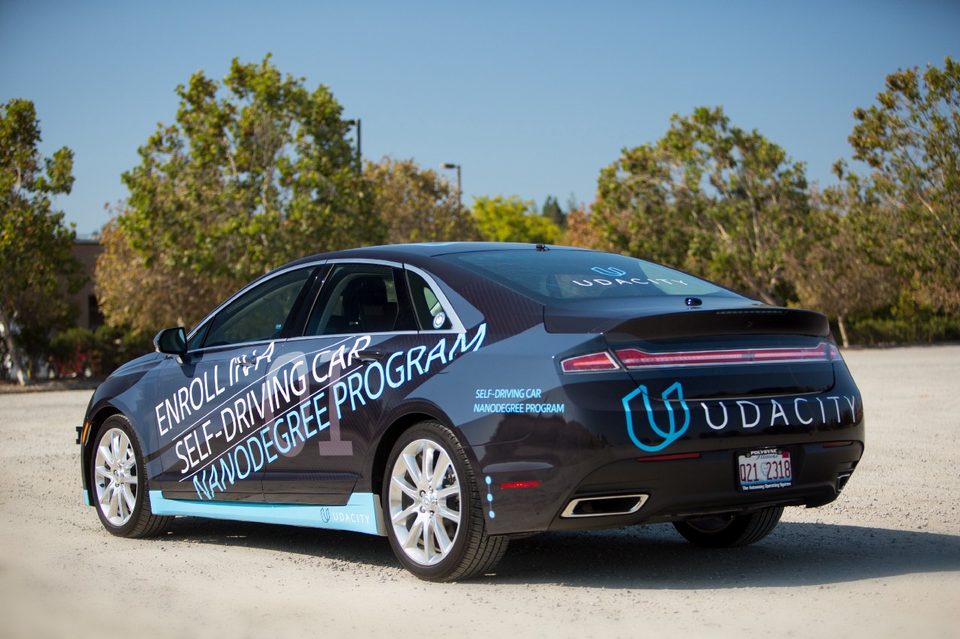
Carla is a Lincoln MKZ equipped with sensors and actuation and processing unit to drive in the real world.
The repo is the result of the collaboration of 4 members, forming the team: CAR-9000.
The team name: CAR-9000 is inspired by 2001: A space odyssey supercomputer HAL-9000.
| Name | Github Account | |
|---|---|---|
| Danilo Romano (Team Lead) | https://github.com/danyz91 | d.romano991@gmail.com |
| Gianluca Mastrorillo | https://github.com/Giangy1990 | mastrorillo.gianluca@gmail.com |
| Hossein Gholizadeh | https://github.com/fpgholizadeh | fpgholizadeh@gmail.com |
| Sardhendu Mishra | https://github.com/Sardhendu | sardhendumishra@gmail.com |
Please use one of the three installation options.
-
Be sure that your workstation is running Ubuntu 16.04 Xenial Xerus or Ubuntu 14.04 Trusty Tahir. Ubuntu downloads can be found here.
-
If using a Virtual Machine to install Ubuntu, use the following configuration as minimum:
- 2 CPU
- 2 GB system memory
- 25 GB of free hard drive space
The Udacity provided virtual machine has ROS and Dataspeed DBW already installed, so you can skip the next two steps if you are using this.
-
Follow these instructions to install ROS
- ROS Kinetic if you have Ubuntu 16.04.
- ROS Indigo if you have Ubuntu 14.04.
-
- Use this option to install the SDK on a workstation that already has ROS installed: One Line SDK Install (binary)
-
Download the Udacity Simulator.
Build the docker container
docker build . -t capstoneRun the docker file
docker run -p 4567:4567 -v $PWD:/capstone -v /tmp/log:/root/.ros/ --rm -it capstoneTo set up port forwarding, please refer to the "uWebSocketIO Starter Guide" found in the classroom (see Extended Kalman Filter Project lesson).
- Clone the project repository
git clone https://github.com/udacity/CarND-Capstone.git- Install python dependencies
cd CarND-Capstone
pip install -r requirements.txt- Make and run styx
cd ros
catkin_make
source devel/setup.sh
roslaunch launch/styx.launch- Run the simulator
- Download training bag that was recorded on the Udacity self-driving car.
- Unzip the file
unzip traffic_light_bag_file.zip- Play the bag file
rosbag play -l traffic_light_bag_file/traffic_light_training.bag- Launch your project in site mode
cd CarND-Capstone/ros
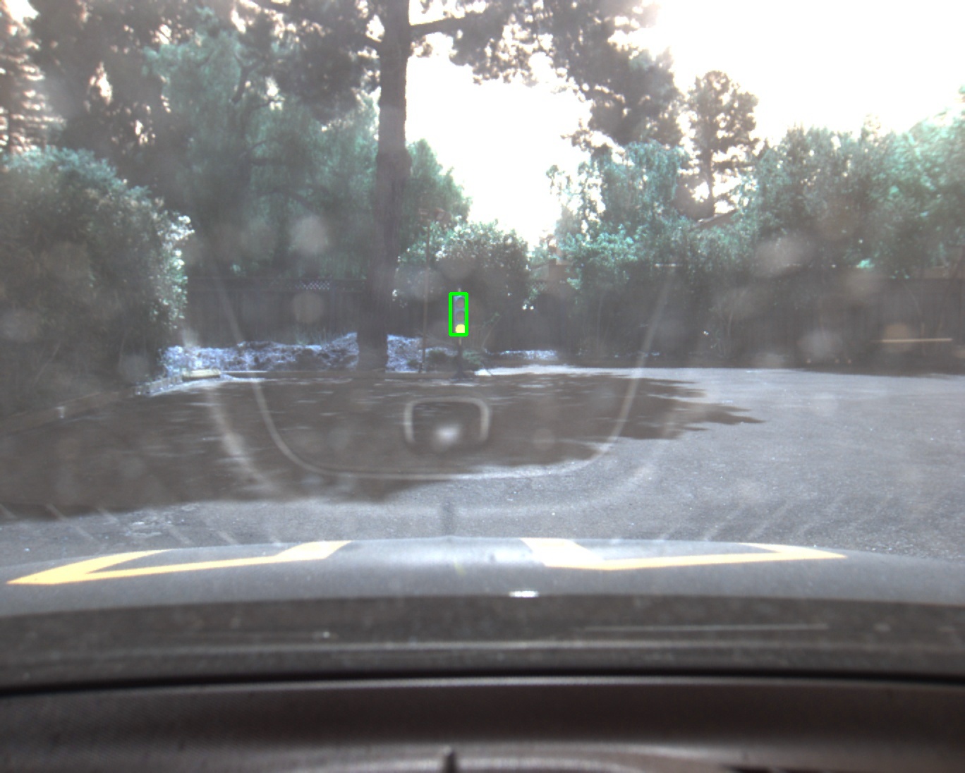
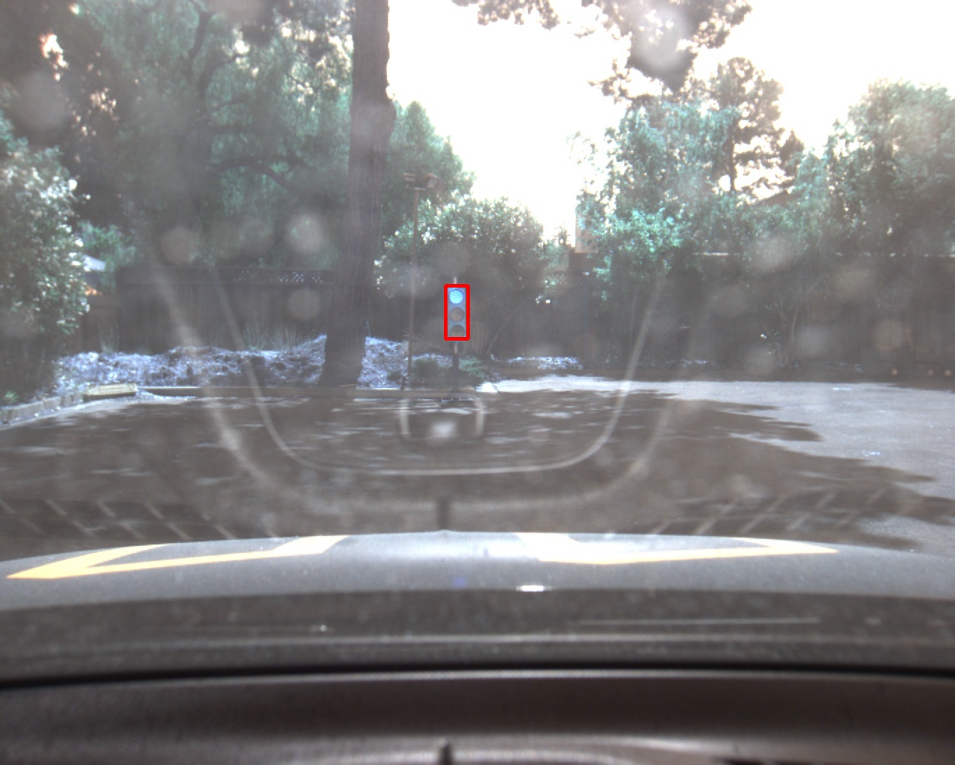
roslaunch launch/site.launch- Confirm that traffic light detection works on real life images
Carla is a Lincoln MKZ equipped with sensors and actuation and processing unit to drive in the real world.
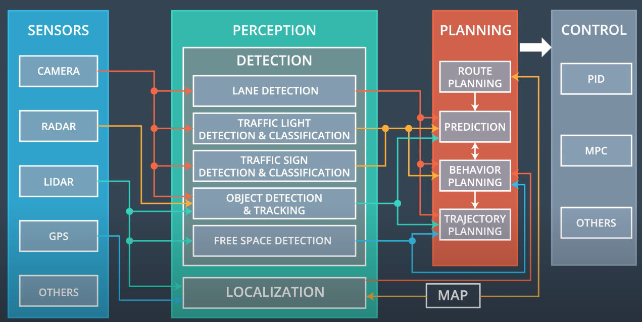
The overall software architecture is shown in the image below.
The main system is divided in three subsystems:
- Perception subsystem
- Planning subsystem
- Control subsystem
It is the center of understanding of the environment, where analysis of the environment takes place.
It could be divided in:
- Perception
- Analyzes camera images, lidar point clouds to understand objects in the environment
- It answer the question "Which and where are other objects in the environment?"
- Localization
- Use sensor and map to understand where the vehicle is
- It answer the question "Where is ego vehicle in the world?"
Given sensor data it has to decide which trajectory to follow
It is divided in 4 subsystems:
- Route planner:
- The route planning component is responsible for high-level decisions about the path of the vehicle between two points on a map; for example which roads, highways, or freeways to take.
- It answers the question "How to connect two points on the map?"
- Prediction:
- The prediction component estimates what actions other objects might take in the future. For example, if another vehicle were identified, the prediction component would estimate its future trajectory.
- It answers the question "What other vehicles are going to do?"
- Behavior planning:
- The behavioral planning component determines what behavior the vehicle should exhibit at any point in time. For example stopping at a traffic light or intersection, changing lanes, accelerating, or making a left turn onto a new street are all maneuvers that may be issued by this component.
- It answers the question "Which maneuver ego vehicle needs to take?"
- Trajectory generation:
- Based on the desired immediate behavior, the trajectory planning component will determine which trajectory is best for executing this behavior.
- It answers the question "How to generate a trajectory to execute the maneuver?"
- The control subsystem takes in input the trajectory to follow and implements control algorithms to compute commands to send to the actuators.
- It answers the question: "How much do the car needs to steer/throttle to follow the selected trajectory?"
The image above illustrates the system architecture diagram showing the ROS nodes and topics used in the project. This can be used as reference to understand the overall ROS architecture. The ROS nodes and topics shown in the diagram are described in sections below.
In addition to the nodes here shown, The repo contains also styx and styx_msgs packages used to provide a link between the simulator and ROS, and to provide custom ROS message types:
-
A package that contains a server for communicating with the simulator, and a bridge to translate and publish simulator messages to ROS topics.
-
A package which includes definitions of the custom ROS message types used in the project.
-
A package which loads the static waypoint data and publishes to
/base_waypoints. -
A package containing code from Autoware which subscribes to
/final_waypointsand publishes target vehicle linear and angular velocities in the form of twist commands to the/twist_cmdtopic.
The three main blocks of the ROS architecture are:
-
Waypoint updater node
This node has the role of selecting the speed of waypoints in front of ego vehicle in order to navigate the race track and to stop when necessary
-
Drive-by-wire node
This node has the role of implementing control algorithms to control steering wheel and throttle in order to follow the reference line at desired speed.
-
Traffic light detection node
The design and implementation details about each of these nodes is provided below.
The purpose of this node is to update the target velocity property of each waypoint based on traffic light and obstacle detection data.
This node subscribes to the /base_waypoints, /current_pose, /obstacle_waypoint, and /traffic_waypoint topics, and publish a list of waypoints ahead of the car with target velocities to the /final_waypoints topic.
The core functionality is implemented in class WaypointUpdater class of file waypoint_updater.py.
In the constructor of this class, publishers and subscribers are registered at lines 43-56.
The respective callbacks for all subscribed topics are defined at lines 136-155.
Some callback details are:
- The waypoints callback stores all the waypoints in KDTree structure. This structure has been selected because it is particularly efficient in retrieving spatial nearest neighbors to a given location.
- The obstacle callback function is missing since it is not required for the current project.
The main routine is implemented in function loop() defined at lines 61-67. Here when data is available through the callbacks, the final_waypoints topic is published. This function heavily relies on the execution of the lane generation function: generate_lane().
The function generate_lane() is defined at lines 97-110. This function implements the creation of the lane that car needs to follow. Its implementation is divided mainly in 3 steps:
- Find closest waypoint to ego car within all incoming waypoints
This is implemented in class method get_closest_waypoint_idx defined at lines 69-91.
Here the closest waypoint is found using KDTree class attribute filled in waypoints callback. Then it is checked if closest waypoint is ahead or behind vehicle, by extracting the equation for hyperplane passing through two closest points.
- Extract a set of waypoints in front of ego vehicle
This is implemented using python slicing functionality. This is implemented at line 102. Here a fixed length subset of all waypoints is selected. The number of selected waypoints is defined through the variable LOOKAHEAD_WPS defined at line 25. This value is currently set to 50.
- Update velocity of each waypoint basing on incoming traffic lights info
If no stop is required then the generated lane can be published, otherwise stop deceleration profile is implemented in class method decelerate_waypoints defined at lines 112-134.
Here the linear deceleration profile is used to updated velocity information associated with each waypoint in front of ego vehicle. The deceleration value follows the value of variable MAX_DECEL defined at line 26.
Two more details here are that we choose to stop a little before the actual stop point incoming from perception in order to stop the car before traffic light line and that the total velocity is always checked to be below maximum allowed speed.
The control is last node in the self-driving car system. It sends the command to the actuator preset on the vehicle to make it follow the planned trajectories.
In the below figure it is possible to see the interface of this node.
The file twist_controller.py contains all the logics to fulfill this task.
The first check regards the dbw status. This is a fundamental check since it resets the controller when the user takes back the control of the vehicle to drive itself.
When the dbw is enabled, this node actuates three different logics to respectively generate the steer, throttle and brake commands.
This controller translates the proposed linear and angular velocities into a steering angle based on the vehicle’s steering ratio and wheelbase length. To reduce possible jitter from noise in velocity data, the steering angle computed by the controller is also passed through a low pass filter
The throttle is computed using a PID controller that compares the current velocity with the target velocity and adjusts the throttle accordingly.
In case of negative speed error or computed throttle command less than 0.1, the throttle command will be set to 0 and a brake command will be computed. The brake controller is a simple computation that takes into consideration the vehicle mass, the wheel radius, as well as the brake_deadband to determine the deceleration force.
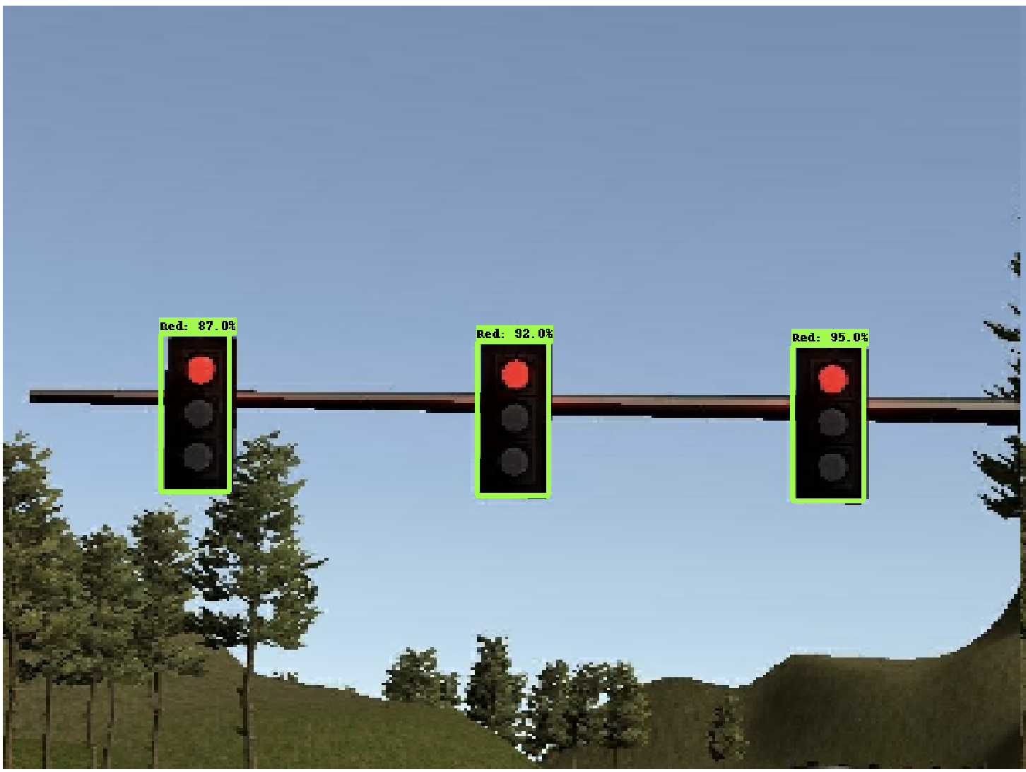
This node subscribes to the /base_waypoints, /current_pose and /image_color topics, and publishes the traffic waypoints. The published traffic waypoint can be used to determine the closest traffic and weather to stop/pass the traffic light based on the color.
The core functionality for the node is implemented in class TLDetector class of file tl_detector.py. In the constructor of this class, publishers and subscribers are registered at lines 52-58. The core functionality of the traffic_light_classifier that performs the inference on an image can be found at ./ros/tl_detector/light_classification/tl_classifier. In a nutshell, this part of the code loads the model and performs inference on a new image.
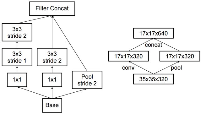
Network: To train the model we used TensorFlow object detection API - a framework with several model architecture to train and evaluate object detection task. TensorFlow provides a model zoo pre-trained on various datasets. We decided to use the object detection model pre-trained on the COCO dataset since it already contains the traffic light category and will be helpful for our final model tuning. We use “ssd_inception_v2_coco” to have a good trade-off between computation cost and model efficiency. We use a SSD with the Inception V2 backbone. Inception was originally introduced by Google to reduce the computational complexity of the network while maintaining its efficiency. Central to inception models are the inception blocks where the input feature maps are convoluted with multiple kernels with size 3x3 and 1x1. Having smaller kernels helps the models to the computationally efficient, since smaller kernel requires less Floating-point operations. A typical bounding box models uses predefined anchors to localize objects. Anchors with high score relates to the foreground class (object class) and anchors with low score relates to the background_class. Additionally, most bounding box models are trained to optimize two different losses.
- Classification loss: A simple cross-entropy loss to learn the label of a bounding box
- Localization loss: (Regression loss): L1-smooth, GIOU or IOU loss are typically used. In layman terms this loss tend to penalize prediction boxes, if they dont have high overlap with the ground truth.
Dataset: To perform the training, we need to gather reasonable amount of traffic light images from both the simulator and ROSbag file from Carla. One can easily run the simulator and take pictures of traffic lights. However, after taking the pictures, they all need to be labeled. The recommended labeling tool is labellmg. We ended up using the dataset already created and labeled by Alex Lechner. Here you can also find step by step guide on how to prepare the data and labels.
Modeling: Training can be divided into three major parts.
-
Data Preparation: Converting coco-format or XML data to tf-records. We have provided several parsers to easy the creation of tf-records. We would also recommend inside the awesome step-by-step guide by Daniel Stang
-
Staging experiment:
- Install tensorflow object detection API
- Get the pretrained coco weight from model zoo
- Create a label.pbtxt file to map labels to the class name.
- Get the model config and update the following
- Change “num_classes” to the number of classes we have, here would be 4 (Red, Yellow, Green, Unknown)
- Change “max_detections_per_class” and “max_total_detections” to lower values such as 10-15.
- The fine_tune_checkpoint: "PATH_TO_BE_CONFIGURED/model.ckpt" need to be changed to the directory where you downloaded the model
- Change “num_steps” to 5000. Empirically, we found 5000 steps were sufficient for the training to settle.
- Change PATH_TO_BE_CONFIGURED placeholders in “input_path” and “label_map_path” to your .record file(s) and label_map.pbtxt
- Start Training
python model_main.py \
      --logtostderr \
      --model_dir=path_where_to_save_the_model_checkpoints \
      --pipeline_config_path=path_to_config_file/ssd_inception_v2_coco.config
-
Creating Saved Model: In order to serve the model with the Udacity's system, we require the model to be compatible with the tensorlfow==1.3.0 version. A simple way to do this is the checkout the object-detection api branch 1f34fcafc1454e0d31ab4a6cc022102a54ac0f5b and export the model graph as a probuff using contents from this branch.
python export_inference_graph.py \
 --input_type image_tensor \
 --pipeline_config_path=PATH_TO_/ssd_inception_v2_coco.pbtxt\
 --trained_checkpoint_prefix CHECKPOINT/model.ckpt-4200 \
 --output_directory  OUTPUT_FORZEN_MODEL_DIR

 # Some changes to avoid errors
 1. comment line 96-98
 2. ./builders/model_builder: batch_norm_trainable: False #feature_extractor_config.batch_norm_trainable
 3. Change object_detection/exporter line 71 to rewrite_options = rewriter_config_pb2.RewriterConfig()
The above snippet creates a saved_model called as "frozen_inference_graph.pb" which contains both the weights and the model_graph.
Deployment For deployment we simple copy the "frozen_inference_graph.pb" file to our ros directory with the name model_weights and hook the client code into ./ros/tl_detector/light_classification/tl_classifier.py
-
Training:
The result of the developed system is shown in the video below
The car is able to follow lane in the simulator and to stop when traffic light is red. It is also shown how the car starts again when the green traffic light is detected. When the car approaches the second traffic light, it does not come to a full stop since the traffic light is correctly classified as green.
The project has been a great opportunity of collaboration and an exciting experience of running software on real self-driving car!
Our team was organized in two continents (USA and Europe) with 7 hours of time difference! It has been a great opportunity to organize work taking into account this constraint and to collaborate together. All team members have worked intensely and the team met several times to sync and organize tasks.
Such a thrilling experience!

