"Bert" is a nickname given to a UART RPC interface client of PSP2's System Controller.
The PlayStation Vita/TV's System Controller - codenamed "Ernie" - is a low-power MCU that handles peripherals such as PMIC, USB controller, physical buttons, touch panels and more.
It hosts a RPC server accessible from multiple interfaces, each of which has its own set of available commands.
One of the interfaces is UART, enabled by a special "jig" circuit that sets specific voltage levels on syscon's voltage sense pins/probes.
This interface exposes around 100 RPC commands ranging from simple peripheral details retrieving to more complex procedures such as flash programming or alternative SoC boot modes.
In this repository you will find documentation, schematics, diagrams and scripts for interacting with Syscon over the UART interface.
Supported units:
- DEM-3000 : only IRT-002
- unknown interface-enable procedure on IRT-001 / "slideys"
- CEM-3000 : supported
- PDEL-1000 : supported
- PCH-1000 : supported
- VTE-1000 : supported
- PCH-2000 : supported
For all supported units, the UART interface logic level is 1.8v.
On those units, the circuit probes as well as Syscon UART are exposed via the MultiConnector.
- Pin 6: Syscon RX
- Pin 7: Syscon TX
- Pin 11: Jig Sense 1
- Pin 12: Jig Sense 2
- Pin 14: GND
The UART interface is enabled if the "Jig Sense 1" probe is at 0.47v-0.738v during "Jig Sense 2" probe state change.
State change can be achieved by connecting the probe to GND using a button or jumper wire.
A MultiConnector breakout board is recommended.
The biggest challenge is finding a populated connector, we found that the PCH-ZCL1 "Sony PlayStation Vita Cradle" has one, but it is hard to source.
Another possibility is using the motherboard's tiny testpads, or lifting and moving pins on a retail USB MultiConnector cable.
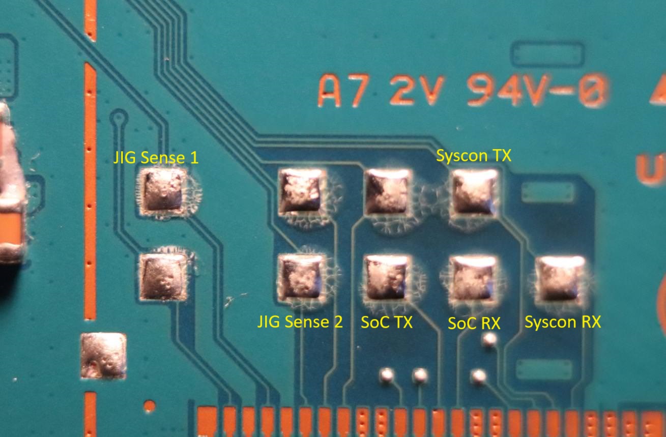
On this unit, the circuit probes as well as Syscon and SoC UART are exposed via the Service Connector.
- Pin 1: GND
- Pin 4: Jig Sense 1
- Pin 6: Jig Sense 2
- Pin 13: SoC TX (useful)
- Pin 14: SoC RX (useful)
- Pin 19: Syscon TX
- Pin 20: Syscon RX
It is recommended to use the big testpads above the flat connector:
The UART interface is enabled if the "Jig Sense 1" probe is at 0.47v-0.738v during "Jig Sense 2" probe state change.
State change can be achieved by connecting the probe to GND using a button or jumper wire.
On this unit, the circuit probe as well as Syscon UART are exposed via microUSB.
- Pin 2: D- : Syscon TX
- Pin 3: D+ : Syscon RX
- Pin 4: ID : Jig Sense
- Pin 5: GND
The UART interface is enabled if the "Jig Sense" probe is at 1.017v-1.14v for at least 32000 Syscon clock cycles. When enabled, a "UUU" hello packet is sent over UART.
A microUSB breakout board is recommended, it is also possible to use the motherboard's big testpads.
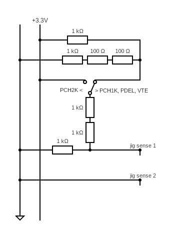
The following circuit will enable the Syscon UART interface on all supported units:
The UART RPC interface protocol is a simple message -> reply packet interaction, structured as below:
struct _ernie_cmd {
    uint16_t id; // Command ID
    uint8_t ret; // 0x00 for message, return status for reply
    uint16_t data_size;
    uint8_t data[data_size];
    uint16_t checksum; // ~(all bytes added)
} _ernie_cmd;
Each packet is converted to/from ASCII and ends in CRLF, max packet size is 0x40 bytes (ascii 0x80).
A list of all available commands can be found in commands.md.
The reply contains a command return status, currently the following status IDs are known:
- 0x0 : "OK"
- 0x1 : "UNK_CMD"
- 0x2 : "BAD_LEN"
- 0x3 : "BAD_CHKSUM"
- 0x4 : "NO_CRLF"
- 0x5 : "BAD_CMD_FORMAT"
- 0x10 : "LOCKED_HANDSHAKE"
- 0x20 : "LOCKED_T1"
- 0x32 : "BAD_ARG_SIZE"
- 0x33 : "BAD_ARG"
- 0x40 : "WRONG_STATE"
- 0x50 : "WRONG_POWER_STATE"
Some commands are locked behind "locks" - bits that can be set using other commands.
For example the power control command - 0x105 - requires the T1 "lock" to be removed/unlocked by first calling cmd 0x103.
Some commands, such as NVS-read (0x131), might be locked behind multiple "locks" - here besides T1, the T8 lock needs to be removed/unlocked first by performing a 3-step keyset 0x1 handshake with cmd 0x110.
Full list of commands with their locks can be found there
Un/lock, where Tx is the "lock" bitmask:
- T1: 0x103 / 0x104
- T2: 0x110 keyset 0x1
- T4: 0x900 with key / 0x901
- T8: 0x110 keyset 0xE
Provided is a python script that can be used to communicate with the RPC server over UART.
- requires pyserial, pycryptodome, python 3.10+
bert.py raw [COMMAND]                               : send a raw command, only adds checksum           : -----
bert.py nop                                         : ping ernie                                       : 0x100
bert.py mode [USE_FAST?] [USE_BIN?]                 : [true/false] 115200 and binary uart modes        : 0x102
bert.py info                                        : get hardware & ernie info                        : 0x101
bert.py get-date-string                             : get ernie firmware date string                   : 0x107
bert.py power-off / power-on / power-fsm            : set new power state                              : 0x105
bert.py get-power                                   : get current power state                          : 0x106
bert.py get-kr600                                   : read some ID with overlord command 4, off 0x120  : 0x120
bert.py maika-0 [OFFu16]                            : read some data with overlord command 0           : 0x121
bert.py nvs-read [OFFu16] [SIZEu8]                  : read nvs                                         : 0x131
bert.py nvs-read-range [OFFu16] [ENDu16] [STEPu8]   : read and print nvs in STEP-sized blocks          : -----
bert.py nvs-write [OFFu16] [SIZEu8] [DATA]          : write nvs                                        : 0x132
bert.py confzz-ro / confzz-rw                       : block/allow confzz writes                        : 0x144 / 0x143
bert.py confzz-read [OFFu16] [SIZEu8]               : read confzz                                      : 0x141
bert.py confzz-read-range [OFFu16] [ENDu16] [STEPu8]: read and print confzz in STEP-sized blocks       : -----
bert.py confzz-write [OFFu16] [SIZEu8] [DATA]       : write backup confzz                              : 0x142
bert.py confzz-apply                                : write backup confzz to main confzz               : 0x145
bert.py invs-read [OFFu16] [SIZEu8]                 : read internal nvs                                : 0x154
bert.py invs-read-id [IDu8]                         : read internal nvs by id                          : 0x153
bert.py invs-read-range [OFFu16] [ENDu16] [STEPu8]  : read and print internal nvs in STEP-sized blocks : -----
bert.py wipe-nvs                                    : wipe NVS with 0xFF                               : 0x160
bert.py reset / reset-hard                          : soft-reset / hard reset ernie                    : 0x161 / 0x162
bert.py kill                                        : full, hard shutdown of all components            : 0x163
bert.py reset-bic                                   : reset the battery controller                     : 0x182
bert.py unlock-1 / lock-1                           : un/lock the T1 lock                              : 0x103 / 0x104
bert.py unlock-4 / lock-4                           : un/lock the T4 lock with a passcode              : 0x900 / 0x901
bert.py handshake-0 / handshake-1 / handshake-E     : authenticate with the selected keyset            : 0x110
bert.py unlock-qa                                   : unlock the T1 and T8 locks                       : 0x103 + 0x110 (E)
bert.py unlock-nvs                                  : unlock the T1 and T2 locks                       : 0x103 + 0x110 (1)
bert.py unlock-sdboot                               : unlock the T1 lock and boot into SD mode         : 0x103 + 0x110 (0)
bert.py unlock-all                                  : unlock 1,4,qa,nvs,sdboot                         : -----
bert.py [COMMANDu16] <SIZEu16> <DATA>               : execute a command, e.g. '0x105 0x2 03'           : -----
- Some breakout/jig PCB schematics and gerber files can be found in PCBs
- Alternative JIG schematics can be found in schematics
- This project is WIP, the syscon firmware is still being reversed and commands documented.
- It is not recommended trying unknown commands, they might cause an unrecoverable brick
- It is not recommended trying unknown commands, they might cause an unrecoverable brick
This project was made in collaboration with Proxima.
Additional thanks to:
- yifanlu, for initial syscon JIG research and documentation
- pop13_13, for help with finding the PCH-2000 JIG circuit
- S1ngyy, for help with finding the PCH-1000 JIG circuit
- xyz, for help with finding the VTE-1000 JIG circuit
- Mathieulh, for alternative PCB schematics and circuits
- d3s, for the multiCn breakout board
- SonicMastr, for ideas and early tests
- Everyone that contributed ideas, tested and helped debug the JIG circuits
- henkaku wiki contributors.

