Updating/Retro Fitting the sensors on an engine balancing machine...
An engine balancer is a simple electro-mechanical machine, that just happens to be blessed with a little magic for it to work. Functional components consist of:
- Roller Assembly
- Crank Angle Sensor
- Drive Motor
- Instrumentation

The roller assembly sit on a structure that is designed to act as a pendulum. The pendulum is trussed by two steel strips that restrict the movement. A Load Cell is fixed to the rear strap. The entire structure sits on a solid bed, and can be positioned to suit various shaft bearing widths.
When the crankshaft is spun by the drive motor any imbalances will cause the pendulum to exert a force on the Load Cell.

Once we have a notional force we need to give it context, for this we want the angle of the crank. This machine uses an aluminium disk with a steel grub screw to excite a variable reluctance sensor.

Its a big ugly 3-phase thing that will spin the shaft at a set speed, thankfully because it works perfectly well we don't have to worry about it.
Somehow due to magic (this thing originally used valves, and was transistorised in the 1980s) the forces read from the Load Cells are presented with their reference angles. There are some frightening looking boxes with wires, and a whole heap of calibration trim pots that defy description.

The physical structure of the Assembly will not need any substantial changes, but the Load Cell will be updated.
Three photo interrupters will be used with two slotted disks
- Two interrupters on a multi-slotted disk to provide angle and direction. (See 'Further Description, Including Encoder Waveform' section of Arduino Playground - Rotary Encoders )
- One interrupter on a single slot disk to provide a synchronisation pulse, denoting 0 degree.
Its a terrifying thing, and is to be left alone.
The idea is to embrace the mantra
Perfect is the enemy of Good Enough
So I'm using things that already work, and a nice simple way of coding them.
Things that already work are:
- Arduino Mega 2560
- Robot Shop's Strain gauge load cell amplifier sheild
- Opteck OPB830W Photo Interrupters (http://datasheet.octopart.com/OPB830W55Z-TT-datasheet-5310085.pdf)
- Python based Graphical display.
We have machined an optical trigger disk which gives us 1 degree accuracy.

Which uses the three photo interrupters to provide position and direction.
If you look towards the bottom of the disk (at ~ 4 o'clock) you will see an extended slot to provide rotational synchronisation.
Before mounting, we tested the disk on a lathe to ensure that the photo interrupters would work with the disk at the ~500rpm speed that the balancer operates at.

We found that the original interrupters with a 1mm window were very position sensitive, and failed to operate above ~400rpm. These were swapped out to sensors with a 0.25mm window which worked well, even for speeds greater than 650rpm.
The original load cell consists of two strain gauges either side of a steel strip

Which would work as a Quarter Bridge Strain Gauge
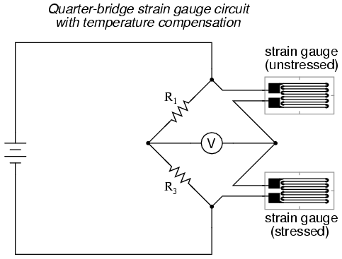
See All about Circuits page for a proper description.
Because these are very old, and also because I don't fully understand how they're meant to be setup with the Load Cell Amplifier, I decided to use a 50kg micro loadcell from RobotShop. I lashed up a temporary mount to test the balancer hardware.

The net result was that the load on the load cell from an unbalanced crank could not be read by the 50kg resolution sensor, so we have ordered a number of lower load cells and will try them in turn. We were able to see the signal from the load cell changing when we pulled or pushed on the balancer cradle so decided that the resolution is far to low to be any use with this sensor.