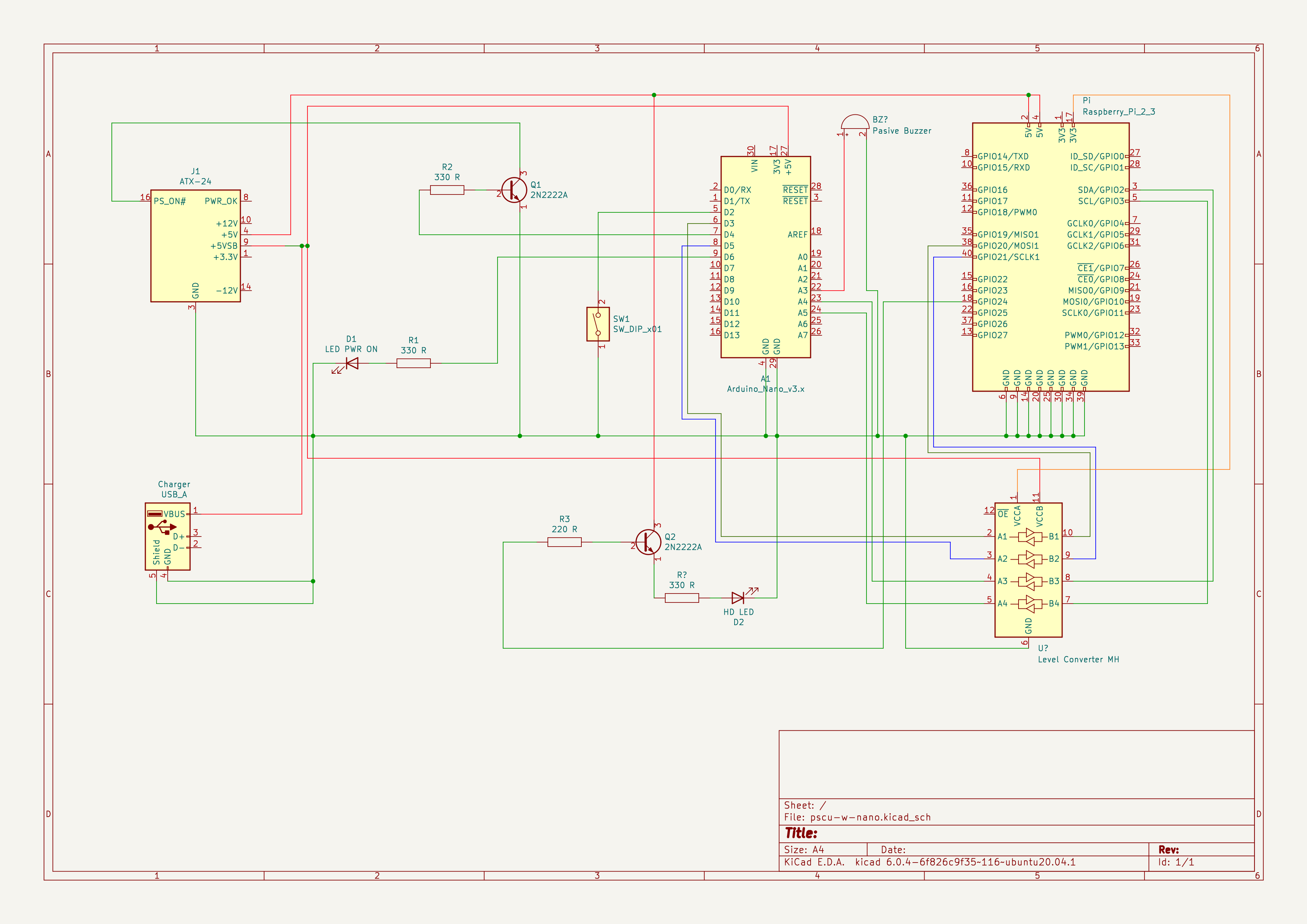
You can use this solution as a Power Supply Unit controller for Raspberry Pi, Terasic DEx boards or any other SoC projects requiring external power.
Initially this project was developed as a part of "MachineKit on DE10-Nano" project.
Default controller type is Arduino Mini Pro 5V, PS is PicoPSU.
WARNING: do not connect both 5V from ATX +5VSB and serial programmer the same time when you are flashing controller !!!
WARNING: Verify that VSB is 5V, and that PS_ON is 3.3V.
Components:
- Arduino Nano
- Transistor 2N2222A
- Transistor resistor 330 R
- Led resistor 330 R
// set to 1 if you want to set HIGH gpio signal for external hardware
// before power down and wait for confirmation signal
// if 0 power will be turned off immediately
#define PSUC_USE_CONFIRMATION_GPIO 1

// set to 1 if you want to use arduino on-board led
#define PSUC_USE_ONBOARD_LED 1

// set to 1 if you want to use external (case) led
#define PSUC_USE_EXTERNAL_LED 1

// IMPORTANT!!! this is depends on your ATMEGA->[ATX PS_ON PIN] hardware implementation
// set it to LOW if you connected cpu directly to PS_ON
// set to HIGH if you used NPN transistor switch
#define PSUC_PSON_SIGNAL HIGHedit /boot/config.txt and add at the end:
# External ACT led
dtparam=act_led_gpio=24

# Power off signal in GPIO
dtoverlay=gpio-poweroff,gpiopin=20
dtoverlay=gpio-shutdown,gpio_pin=21,active_low=0
The external ACT led will respond to SD activity, if you want see an external HDD activity you can use the next Python script: https://github.com/thagrol/hdd-led
The two last lines use new GPIO functionality to shutdown and poweroff signals.
Application implements a simplest state machine:
- turn on, init PSUC and go to 1
- sleep and wait for signal on button line, if button is pressed go to 2
- turn on atx power supply and go to 3
- sleep and wait for signals on button and gpio lines, if received gpio request go to 5, if button is pressed go to 4
- run 60 seconds and check states for button and gpio lines, if gpio request is received go to 5, if button is pressed for < 10 seconds go to 3, if more than 10 seconds goto 5. after 60 seconds of inactivity on all lines go to 3
- turn off atx psu and go to 1
- turn on, init PSUC and go to 1
- sleep and wait for signal on button line, if button is pressed go to 2
- turn on atx power supply and go to 3
- sleep and wait for button signal, if button is pressed go to 4
- turn off atx psu and go to 1
Theoretically you can exclude NPN switch and connect PS_ON to arduino pin directly
In this case change
#define PSUC_PSON_SIGNAL HIGHto
#define PSUC_PSON_SIGNAL LOWPLEASE do not forget to check current consumption on PS_ON pin for your PSU, for example (my!) PicoPSU consumes only 6 ma. Atmega pin maximum is 40 ma.
- implement IPMI ?
- get rid of arduino bootloader and implement watchdog ?
