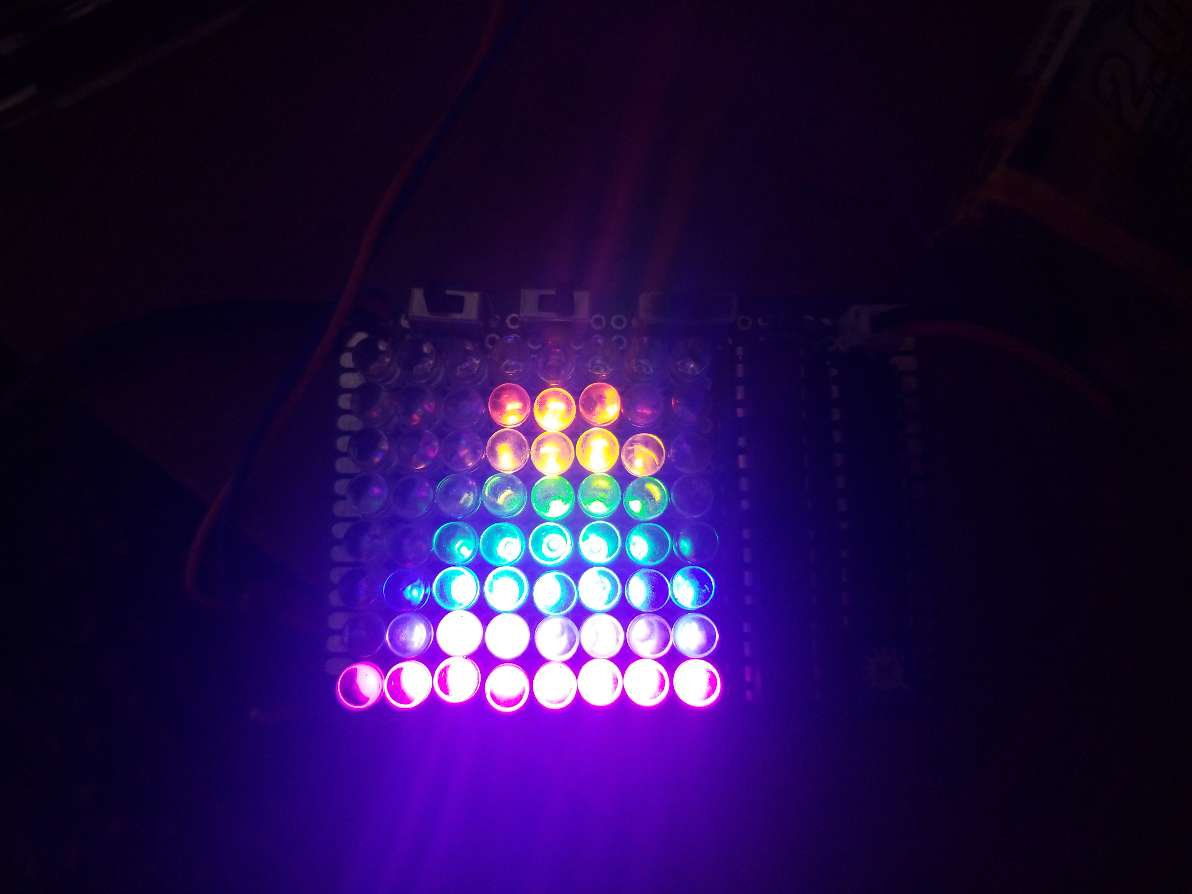
An oscilloscope that no one in their right mind should build
- Channels: 1 floating analog input with selectable fixed falling edge trigger
- Vertical Range: 0-5V (1x), 0-15V (3x)
- Vertical Resolution: 3 bits
- Bandwidth: I don't know
- Sample rate: 150kSa/s
- Horizontal Resolution: 3 bits
- Memory size: 0 points
- Advanced Features: nope
This repo is designed to help people learn how to design something like this, both hardware and software. I hope that this can help others with understanding basic circuit and code ideas that can be put together to make great things.
- Registers controlling the digital IO, timers 0 and 1, and interrupts
- Interrupt Service Routines and their various vectors
- Timer output compare and overflow vectors, and the superb Timer1 in general
- Multiplexing with shift registers
- Flash ADCs using discrete comparators
- How Oscilloscopes, especially Cathode Ray Scopes work: Horizontal and Vertical controls and triggering
- This project's schematic
I used the Arduino IDE to upload this to an ATTINY85 using ISP and Spence Konde's Attinycore, using these settings:
- Board: "ATtiny25/45/85 (No Bootloader)"
- Chip: "Attiny85"
- Clock: "16MHz (PLL)"
- B.O.D.: "B.O.D. disabled"
- Timer 1 Clock: "CPU"
- millis()/micros(): "disabled"
The compiled binary is 642B, allowing usage on even the ATTINY25. Since the code makes use of Timer1, which is pretty much unique to the 'x5 family, it will only work on those. You should probably just use an '85, since it is barely more expensive than a '25 or '45 and with much more flash/RAM.
This project can be built on a 18x24 PTH protoboard, available straight from China for cheap from many retailers, including Amazon. However, I HIGHLY DISCOURAGE THIS, since the construction on such a small protoboard will be terribly complicated. Either use a much larger protoboard, or spin up a PCB for this project. Have fun!
If you are using ordinary 5mm LEDs and you want to pack them as tightly as I did, you will have to use flush cutters to cut some of the "lip" off of the bottom of each LED. Otherwise they simply will not fit. Of course, you could use a premade 8x8 LED multiplexed matrix, which would really simplify some of the worst wiring, but then again now you are stuck with all of the LEDs being the same color. So, really, your choice.
-
When using this scope, it is recommended that you first power up the scope before attaching it to the signal source. Probably nothing very bad will happen if you reverse these; at most some LEDs will, spuriously light up, but I would rather not risk it. This was hard to make!
-
The potentiometer on the bottom right controls the timebase. Turn it all the way counterclockwise, and the scope will complete one sweep at about 30Hz. Turn it all the way clockwise, and the scope will sweep at about 16KHz.
-
The top left switch is the attenuation switch. Left, it passes the signal unattenuated. Right, it drops it to 1/3 of the voltage.
-
The top middle switch is the coupling switch. Left, it sets the DC portion of the signal to about Vdd/2, thus centering the trace in the middle of the display. Right, it passes the signal unchanged.
-
The top right switch is the trigger switch. Left, it sets the scope in free-running mode, starting one sweep after another. Right, it sets the scope into falling-edge trigger mode, in which a sweep will only happen when the signal has a falling edge.
-
The scope does not support measuring signals below its own ground or above Vdd, which is usually a battery voltage and must be between 3 and 5 volts. A 1S Li-ion cell is perfect for this. To measure signals outside this range, attenuate it and/or AC couple it to Vdd/2, via either of the switches.


