
This robot is a true creation of the idea many years ago brought on by Samy Kamkar's robot that "utilized" his algorithm for cracking combination locks. Samy Kamkar never demonstrated his robot actually performing the algorithm, though he implied multiple times that it does do it.
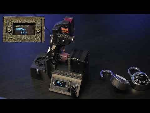
I've always wanted to build a robot that actually decodes locks while maintaining a cool desk toy vibe! I am quite happy with the user-oriented design and doubles as a nice fidgety-toy-thing to play with.
This robot is able to decode the majority of locks that don't have much wear and tear on it and usually takes ~40 seconds.

First number: Turn dial Counter Clockwise while incrementally adding more and more force to the shackle until it suddenly stops. Round down to the nearest whole number and add 14. That is the first number in the combo.
Third number:
- Find the gates between digits 0 - 10 .
- Take the two gates that correspond to a whole number and see whether each of those numbers %(modulo) 4 = firstNum % 4.
- If the equation is satisfied, store that number somewhere. Now add 10 to each number and perform the same operation as the previous step until you have two numbers that satisfy the equation
- Now check the gate size of the two numbers which satisfy the equation. The number with the biggest gate is the third number.
Second number: Guess and check until the lock opens, though it follows a pattern of being (FirstNum % 4) + a multiple of 4.
I found that this video really helped me when trying to program the algorithm.
A TMC2208 Trinamic driver drives a stepper motor & magnetic encoder. These components turn the dial and can detect when the stepper motor stalls.

With this method, any desired number can easily be input into the lock and the lock can be "felt" for it's geometries.

Meanwhile a servo powers a rack and pinion gear which allows precise control of the shackle.

Since I modified the servo with an analog Feedback wire, we can pull up on the shackle and use this to check whether the lock has been opened or not.


Custom PCB powered by a 12V USB C input. An Arduino Nano is the brain and a 5V regulator gives the neccessary voltage for the servo.


KiCAD files are included in the github.
- TMC2208 Stepper Driver
- High torque servos
- Stepper motor
- AS5600 Magnetic Encoder
- Assorted M3 Bolts
- Arduino Nano
- 10uF Capacitor x2
- Diode
- 5V Regulator
- OLED Display
- Rotary Encoder
- Blower Fan
- USB C 12V
- Power Supply