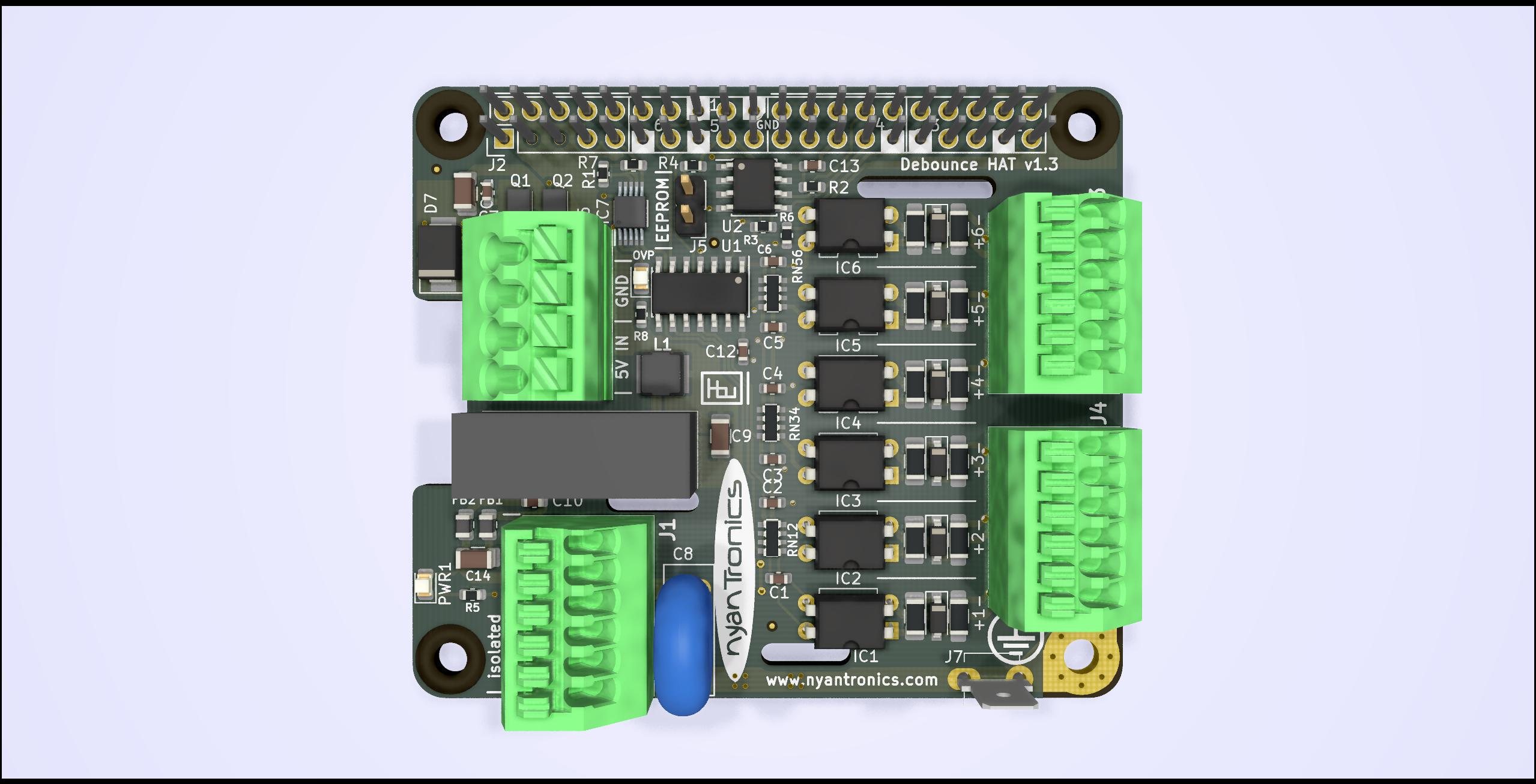
The Debounce HAT provides six opto-isolated digital input channels and is compatible with Raspberry Pi single board computers (SBC) with a 0.1" 2x20 pin header. The Debounce HAT is designed to protect the controller side from electrostatic discharge transients, returning currents through low voltage spark gaps and a dedicated chassis ground connection (PE).
All inputs can be driven with 3 to 24 V with arbitrary polarity. An on-board isolated 5 V DCDC converter provides an uncommitted supply of up to 400 mA for switches, active sensors or remote circuitry. The Debounce HAT implements filtering to suppress fast sequences of level changes typically encountered when using mechanical switches to provide plausible logic inputs to the target.
Further Information
A project page for this board along with ordering information can be found on the Nyantronics site.
Electrical Specifications:
- 6 opto-isolated, uncommitted bipolar inputs (Lo: |Vin| < 1 V, Hi: 3 V < |Vin| < 24 V) with transient protection.
- Isolated DCDC providing 5 V, 400 mA for sensors, switches and remote circuitry (functional isolation, 4 kV DC / 1 s).
- Power terminal with two pairs of 8 A - rated contacts for easy 5 V supply daisychaining to additional devices.
- Advanced input protection with -24 V reverse polarity and +24 V overvoltage capability (load disconnect at >=6.0 V).
- Low ideal diode voltage drop of <200 mV at 3 A.
- >2.4 mm clearance between logic and isolated sides (applies when PE not connected).
- Spark gaps between input pairs.
- Spark gaps between input pins and PE.
- Spark gaps between isolated power and PE.
- Channel probe points marked on pin header for easy setup and debugging.
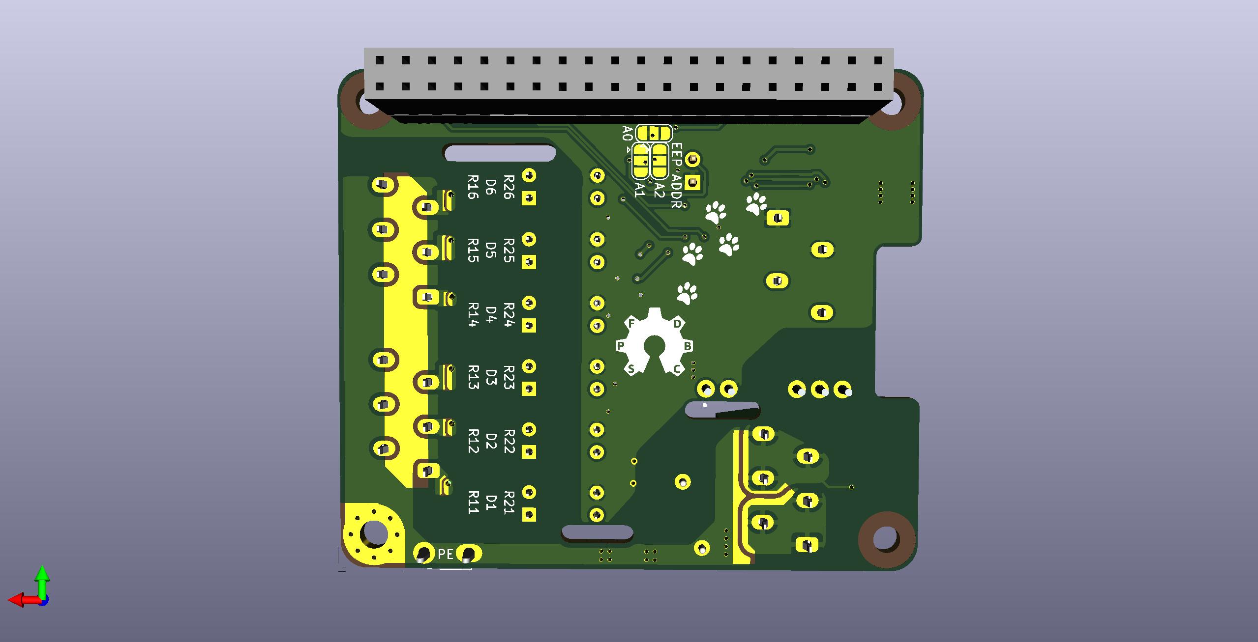
- EEPROM address default 0x50 can be changed via solder jumpers to resolve collision with other HATs (Multi-HAT support).
Mechanical Specifications:
- 3.5 mm pitch terminal block for power in / pass-through (ø 0.2-1.5 mm² / 24-16 AWG).
- 2.5 mm pitch terminal blocks for isolated power and signal (ø 0.2-1.0mm² / 22-16 AWG).
- PE connection via 4.8 mm spade connector and M3 mounting hole.
- Raspberry Pi-compatible mounting hole pattern for M2.5 and M3 polyamide stand-off bolts.
- 16 to 18 mm PCB stacking height (with pre-soldered header, defined by 2x20 pin 0.1" header, other heights available when hand soldering the header).
Typical Applications:
- Digital inputs with ESD protection.
- Mechanical switch / interlock inputs.
- Isolated sensor interface.
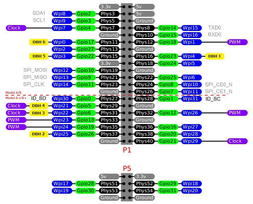
The six channels of the board are mapped to the following GPIO pins:
- BCM 23 (WiringPi 4)
- BCM 26 (WiringPi 25)
- BCM 6 (WiringPi 22)
- BCM 5 (WiringPi 21)
- BCM 22 (WiringPi 3)
- BCM 17 (WiringPi 0)
In the below graphic those pins are marked in yellow (DBH n):
These pins are marked as probe points on the silkscreen of the 2x20 pin header.
The Debounce HAT can be powered from the SBC side. In this case the power terminals are disconnected to avoid back-driving.
When instead a 5V supply is connected to the Debounce HAT power input, the HAT provides advanced input protection, featuring load-disconnect overvoltage protection and low dropout ideal diode reverse polarity protection, making the 5V input and signal inputs +/- 24 V tolerant.
A target voltage of 2 to 5.5 V needs to be provided on pin 17 (typically 3.3 V supplied by the SBC).
With external 5V connected, additional hardware can be connected to the power terminal and draw up to 6 A.
The Debounce HAT provides an isolated source of 5 V for axuilliary circuitry (switches, sensors, other). The on-board DCDC converter is connected to the 5 V pins of the 2x20 pin header (pin 2, pin 4) and active in both above mentioned supply schemes.
The inputs are driven with an external voltage in the range of 3 to 24V. With mechanical switches, a circuit has to be formed with the on-board isolated 5 V output, or with an external power supply.
[Note] The Debounce HAT is not intended to be connected to mains-powered appliances. When a fault condition cannot be excluded in which any contact of the isolated side (signal inputs and isolated 5V) is live, a fuse must be placed between the HAT PE contact and the contact to ground.
The EEPROM configuration is provided in the eeprom_setting.txt file, which can be processed with the eepmake tool, and flashed to the EEPROM with eepflash. Both tools can be found at https://github.com/raspberrypi/hats/tree/master/eepromutils. The jumper (two pin header) allows for the EEPROM to be set to write-protected/write-enabled mode (WP, WE, respectively).
[Note] When not flashing the EEPROM, the EEPROM header should be set to Write-Protect (WP) mode by removing any electrical connection between the |EEPROM| pins on the two-pin header to prevent any accidental rewriting of the EEPROM's contents.
This board design has passed preliminary testing and is provided as-is. No responsibilities for damage or harm caused by its use will be accepted.


