m5stamp-c3dev
![]()
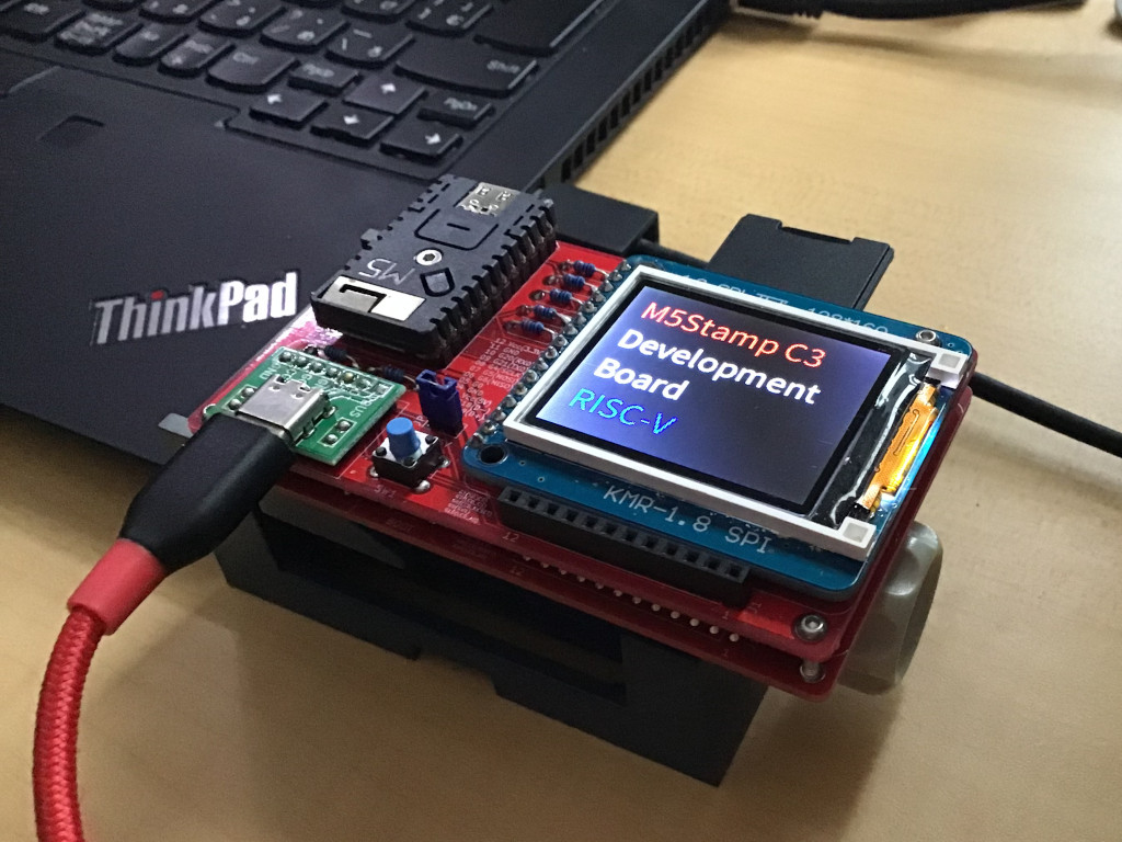
This is a development board for the M5Stamp C3 (RISC-V/FreeRTOS).
Hardware
- External USB-C port for JTAG debugging
- Support for LCD panel and SD card
- Selecting a power supply
- Switch(GPIO9) to enter loader mode
- Pin headers to expose usable GPIOs to the outside
- The size is just Japanese business card
Sample Sources Included
- Japanese TrueType font output to LCD - test_freetype.cpp
- Output PNG images in SD card to LCD - test_tinypng.cpp
- NTP synchronization via WiFi connection - test_nvs_wifi.cpp
- Test I2C sensor connection to GPIO 18 and 19 (UNIT ENV III) - test_i2c_gpio1819.cpp
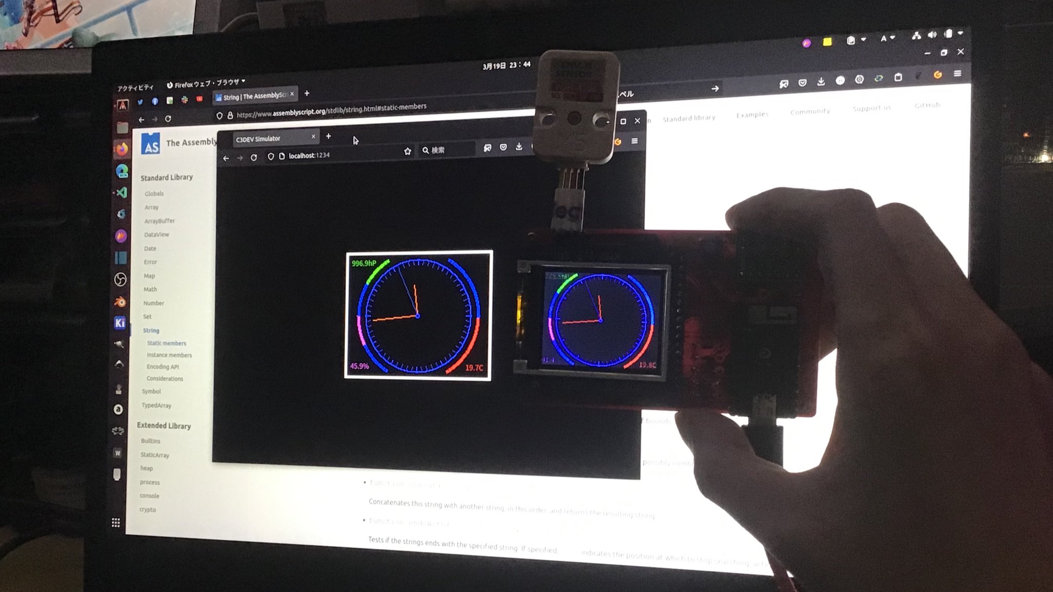
- WebAssembly execution with Wasm3 (sample analog clock using AssemblyScript) - test_wasm3.cpp
- Support RGB LED (SK6812)
- Usage of SPIFFS, which stores TrueType fonts and .wasm binaries (parttool.py and spiffsgen.py tools)
- Use of NVS (cryptographically enabled key value store) that stores WiFi passwords (nvs_partition_gen.py tool)
- Building libraries and managing dependencies using the esp-idf build system
- Visual Studio Code C/C++ Extention configuration and JTAG debugging configuration in conjunction with openocd
- AssembyScript sharing method between web browser and microcontroller - wasm
This repository contains MIT Licensed PCB data and example programs.
Schematic
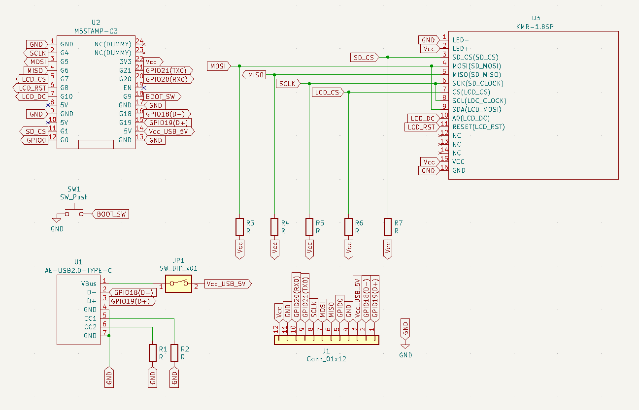
| #Unit | Name | Note | Where to get it |
|---|---|---|---|
| U1 | AE-USB2.0-TYPE-C | USB 2.0 Type-C Break out board | akizukidenshi.com (JP) |
| U2 | M5STAMP-C3 | M5Stamp C3 | + M5Stack + SWITCH SCIENCE (JP) |
| U3 | KMR-1.8SPI | KMR-1.8 SPI marked LCD and SD card interface | + amazon.co.jp (1) + amazon.co.jp (2) + ja.aliexpress.com |
| R1 - R2 | 5.2K Resistor | Pull-down for USB Power supply | - |
| R3 - R7 | 10K Resistor | SPI pull-up | - |
| JP1 | Jumper pin | Select external power supply | akizukidenshi.com (JP) |
| SW1 | Tact switch | for loader mode and utility | akizukidenshi.com (JP) |
| J1 | 12 Pin header | You can use the one that comes with the M5Stamp C3 Mate | - |
PCB and Gerber data
Example Source
Require
With esp-idf 4.4.1 and arduino-esp32 2.0.4 , DHCP for WiFi did not work correctly.
For this reason, We are using esp-idf 4.4.2. But although it is not the correct combination. @see DHCP client failed on 2.0.4 #7068
I (4407) esp_netif_handlers: sta ip: 255.255.255.255, mask: 255.255.255.255, gw: 255.255.255.255
get_idf or (Windows) ESP-IDF 4.4.2 command prompt
# Linux or macOS ->
$ alias get_idf='. $HOME/esp/esp-idf/export.sh'
$ get_idf
# <-

Detecting the Python interpreter
... snip ...
Done! You can now compile ESP-IDF projects.
Go to the project directory and run:

  idf.py build

$ echo ${IDF_PATH}
/home/hiromasa/devel/toolchain/esp/esp-idf

$ riscv32-esp-elf-gcc -v
Using built-in specs.
COLLECT_GCC=riscv32-esp-elf-gcc
... snip ...
gcc version 8.4.0 (crosstool-NG esp-2021r2)
openocd (Optional)
$ openocd
Open On-Chip Debugger  v0.10.0-esp32-20211111 (2021-11-10-21:40)
Licensed under GNU GPL v2
For bug reports, read
        http://openocd.org/doc/doxygen/bugs.html
Build and Execute
git clone and build
git clone --recursive https://github.com/h1romas4/m5stamp-c3dev
cd m5stamp-c3dev
idf.py build flash
Write TypeType font to SPIFFS
parttool.py write_partition --partition-name=font --partition-subtype=spiffs --input resources/spiffs_font.bin
Write WebAssembly(.wasm) to SPIFFS (AssemblyScript Analog Clock)
parttool.py write_partition --partition-name=wasm --partition-subtype=spiffs --input resources/spiffs_wasm.bin
Setup WiFi (Optional)
- Change WiFi Setting
nvs_partition.csv: Set own [ssid], [password]
key,type,encoding,value
wifi,namespace,,
ssid,data,string,[ssid]
passwd,data,string,[password]
- Create NVS Partation file
python ${IDF_PATH}/components/nvs_flash/nvs_partition_generator/nvs_partition_gen.py generate nvs_partition.csv nvs_partition.bin 0x6000
- Write NVS Partation
esptool.py write_flash 0x9000 nvs_partition.bin
Restart M5Stamp C3 (NTP synchronization is performed by pressing the SW1 after the startup logo)
idf.py monitor
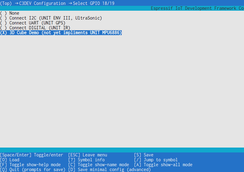
Select connected GPIO18 and GPIO19 device
idf.py menuconfig
JTAG debug with Visual Studio Code
- Set ESP32_TOOLCHAIN_HOME
$ echo ${ESP32_TOOLCHAIN_HOME}
/home/hiromasa/.espressif/tools/riscv32-esp-elf
- Connect the PC to the USB Type-C of the U1
- Open the source file in Visual Studio Code.
- Run Task "openocd (debug)" @see .vscode/tasks.json
- Set a breakpoint in the source code.
- Debug Launch (GDB) @see .vscode/launch.json The first time you start the program, it will often fail, so if you get an error, retry.
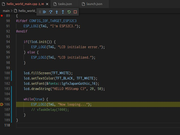
Note
- If the LCD color is inverted.
main/main.cpp
    // If the color is inverted, set to 1.
    tft.invertDisplay(0);
// tft.invertDisplay(1);- Create SPIFFS parteation file
python ${IDF_PATH}/components/spiffs/spiffsgen.py 0x100000 resources/font resources/spiffs_font.bin
python ${IDF_PATH}/components/spiffs/spiffsgen.py 0x10000 resources/wasm resources/spiffs_wasm.bin
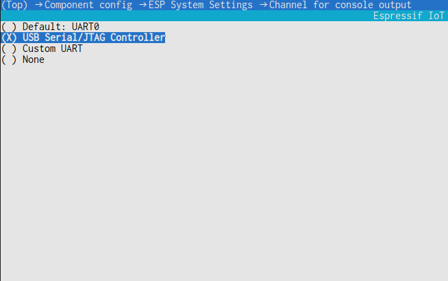
- Change the output destination of the log to U1 Serial/JTAG.(Don't forget to put it back)
Component config → ESP System Settings → Channel for console output
idf.py menuconfig
AssemblyScript and Wasm3
Build AssemblyScript
cd wasm
npm install
Web Browser Development
npm run asbuild:web
npm run start
# http://localhost:1234/
Build and Flash
npm run asbuild
cd ..
python ${IDF_PATH}/components/spiffs/spiffsgen.py 0x10000 resources/wasm resources/spiffs_wasm.bin
parttool.py write_partition --partition-name=wasm --partition-subtype=spiffs --input resources/spiffs_wasm.bin
Dependencies
Thanks for all the open source.
| Name | Version | License |
|---|---|---|
| esp-idf | v4.4.2 |
BSD License |
| esp32-arduino | 2.0.4 |
LGPL-2.1 License |
| M5EPD | 0.1.4 |
FreeType Part(The FreeType License) |
| UNIT_ENV | 0.0.5 |
MIT License |
| Adafruit_GFX | 1.11.3 |
BSD License |
| Adafruit_BusIO | 1.13.1 |
MIT License |
| Adafruit-ST7735-Library | 1.9.3 |
MIT License |
| Adafruit_NeoPixel | 1.10.5 |
LGPL-3.0 License |
| tinyPNG | 0.11 |
MIT License |
| TinyGPSPlus | v1.0.3 |
LGPL |
| wasm3 | master(dc9fa49) |
MIT License |
| AsselblyScript | 0.20.16 |
Apache-2.0 License |
| 源真ゴシック | - | SIL Open Font License 1.1 |
License
MIT License (includes PCB data and example source)