Many model railroad enthusiasts have basements filled with photo-realistic layouts or join clubs with amazing cities and yards. I’m not an enthusiast, but a few years ago I pulled out an old Lionel set I had as a kid and thought a new paint job could make it look less plasticy. I’ve never built a layout (nor would I have room for a large one) but occasionally I’d send a train around a loop or paint a few figures.
![]()
Although I’ve never worked with Raspberry Pi, servos, resistors or done much coding, the balena platform made it easy to get started. It also makes it easy to add and manage additional devices when I’m ready to expand my setup. Although building my first scene still took some effort, I’m happy with the final results (see video at the end).
Every new balenista starts their journey by creating a project as part of their onboarding. This project guide is my reflection of my own residency, allowing me to meet new teammates, get to know the platform, and understand how our users put balena products to work.
To learn more about this unique opportunity, see my article "How We Craft an Entirely Different Onboarding Experience".
I thought it would be fun to think about a specific time and location to ground the model in history. I decided the scene should be on October 31st of 1873 near the Kissena Lake stop of the Central Railroad of Long Island.
The farming community would have celebrated Halloween largely as a festival of the harvest, coming together at large banquites. Although it only ran from 1871 to 1874, the The Central Railroad of Long Island started a transformation in the community, from rural farmland into what would eventually be part of urban New York City.
The center of the operation is a Raspberry Pi running balenaOS and connected to balenaCloud. That way I can flash the device once (using balenaEtcher) and then easily update the code via wifi, making changes in the cloud and never having to take out the SD card again (something that’ll be very helpful if the pi is installed in a layout).
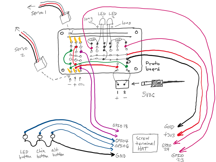
I wanted the project to be robust, but also easy to assemble and change. I started laying out the parts on a breadboard, and then once I was satisfied with my circuit design, I soldered all the parts to a Perma-Proto PCB. That board was then connected to the Raspberry Pi GPIO pins via screw terminals on a HAT.
Most of the basic parts were from the CanaKit Pi 4 Ultimate Kit, which was a good way to start. Each action only needed one additional item: the chicken needed a servo, the lighting needed LEDs, and the sound needed an audio output. The only tools I needed were a soldering iron (with some wire, lead, & flux) and a screwdriver (with some screws).
- Raspberry pi 4 - CanaKit Raspberry pi 4 2GB Ultimate Maker Kit
- SD card
- Screw Terminal Hat - 52Pi RPi GPIO Screw Terminal Hat
- Circuit Board - Adafruit Perma-Proto Half-sized Breadboard PCB
- Power adaptor for the circuit board - 5V 2A (2000mA) switching power supply
- Power connection - Breadboard-friendly 2.1mm DC barrel jack (spec sheet)
- Continuous Rotation Servo - FeeTech FS5103R (spec sheet and more spec sheet)
- Position Based Servo - MCM Electronics TowerPro SG-5 Standard Servo
- Speaker connection - USB Audio Adapter
- Lights - Evil Mad Science Candle Flicker LED Assortment - 15 Piece
- Buttons - 16mm Illuminated Pushbutton
- Soldering Iron - Aven Soldering Iron with Fine Tip - 40W (this is a great beginner tutorial on soldering)
- Solder 60/40 - Rosin Core - 0.5mm/0.02" diameter - 50 grams
- Connections (to easily plug in servos and lights) - Extra-long break-away 0.1" 16-pin strip male header (5 pieces)
- Wire - Hook-up Wire Spool
- Screwdriver and screws
- Speakers to play the audio output
- You’ll need a balenaCloud account – remember: your first ten devices are free and fully-featured!
- The code for this project is available on balenaHub
- Use a tool like Etcher to flash the OS image onto your SD card
- You can also download balenaCLI if you want to get into the nitty-gritty of device management via command line
My project looks very specific to my individual use case, but I mainly want to show how someone can start automating motors and LEDs with balena. You can take this in any direction you want, or just replicate your own version of what I’ve built. It all starts with creating your balenaCloud account and clicking this button to add this project as a Fleet within your dashboard:
The entire project was written in python and can be found here on GitHub. The docker-compose.yml sets up the different containers.
In the Controller directory, the Dockerfile installs the libraries and copies over the code and sound files. The trigger.py is all of the code that runs the servo, light, sound, and buttons. The last command in the Dockerfile runs the trigger.py code upon startup.
When prototyping on the breadboard, it was important to know how to connect the Raspberry Pi 4 to everything else. This GPIO pinout really helped. There is a lot of information on how to use each pin. Once I moved off of the breadboard and onto the screw terminal hat, it became much easier since small LEDs indicated what was active (though there was some confusion for pins with multiple names, like “pin 9” called “MISO”). I used raspberry-gpio-python, a python module to control the GPIO pins on a Raspberry Pi.
The servo was by far the most difficult to work with. Wiring it up was easy. Understanding the basics of the duty cycle wasn’t that bad (though it is interesting how much it’s used in different ways). The challenge came in figuring how to send the correct length pulse to get the movement expected.
The original concept was to have a chicken come out of a chicken coop, move back and forth for a while, and then go back into the coop. I knew it would be possible to do this with electronics or by manually manipulating a stick (like a puppet), but by using software-controlled hardware it would be a lot easier to upgrade this action later, like to coordinate with a day/night cycle or to run away when a train was passing by. The first thing I did was to use household scraps to build a physical proof of concept to make sure that the action made sense. One side mimicked the rotation of the servo to move a wooden skewer while the other side moved the chicken out of the coop.


Next I had to build the chicken action. I used a Raspberry Pi 4, which is a bit overpowered for this role, but I wanted to have the resources ready to keep building on top of this foundation. I used a CanaKit bundle since it came with the wires, resistors, LEDs, etc. that I needed (full parts list below). I learned SketchUp to design a yoke to keep the rod moving in a lateral direction, even though the servo was rotating in a circle. It was mainly just four holes for screws to connect it to the layout and a long, center channel to make sure the rod only moved forward and backwards. As long as I only use around ninety degrees on one side of the servo, I estimated that the yoke would be enough to keep the rod moving in the right direction.

Next I needed a servo to transfer the electrical signal into an action. I chose the FeeTech FS5103R continuous rotation servo. I learned a lot about how sending different length pulses would move a continuous rotation servo clockwise or counterclockwise at various speeds. I set up the timing to move the chicken out of the coop, rock around outside, and then move back into the coop. Since the servo is based on speed, I had to make sure the amount of travel out of the coop equaled the amount back into it.
After working that out I tested it and got inconsistent results. I believe the small, quick movements of rocking the chicken around weren’t consistently being registered so it would occasionally not come back to the home position. This was especially bad for the engineering, since rotating a full 360 degrees would bring the rod so far from its expected path that it may break.
Then I tried to go with a position based servo, where sending a signal would tell it a location, not a speed/direction. I used the TowerPro SG-5 Standard Servo and rewrote the code. I wasn’t happy with Sketchup so I taught myself Blender to design a Scotch yoke, which I thought was safer if the servo did ever go further than expected or if I wanted to ever use the continuous servo for a lateral motion. I created a tapered hole in one end to wedge the stick in and an indented surface for more surface area for the hot glue to stick to.

This new servo didn’t move enough, so I went back to the original continuous servo, but used the Scotch yoke. It’s still inconsistent, but I’m going to keep working with the code to try to improve it in the future.

The basic idea was for the lighting to turn on and off using a switch. I wanted the switch to send a signal to the Raspberry Pi, and for the Pi to send a signal to the LED. That way later we can upgrade the system and connect the lights to a day/night cycle and other more complex actions.
This scene takes place before the Edison Electric Illuminating Company began electrifying Manhattan in 1882 (and well before electricity reached the Eastern Queens building I’m modeling). The lighting in the area may have been from whale oil or kerosene, but I’m modeling candles here since I wanted the lights to flicker. Although we could have flickered the LED by turning it on and off quickly, it was easier just to buy LEDs that flickered on their own.

To simplify the sound, I used a USB Sound Adaptor. One end plugged into a USB on the Raspberry Pi and the other side had a normal speaker jack. One of the benefits of building this on balena is the ability to use “balenaBlocks”, pre-written segments of code ready to use in an application. I was very happy to see an audio block, so most of the challenging coding was already done. This block runs a PulseAudio server optimized for balenaOS and helps route audio from a source to a sink. I decided to use pydub as the audio source in my Python application since it didn’t require much coding or many libraries.
The original sound was in the .mp3 format, but that wasn’t working well so I found one in .wav format. After getting the file into the container and adding the code into my Python program, the audio worked great. I set up the file to play a chicken sound in the middle of the chicken movement.
I could trigger the actions in different ways, but I thought physical buttons would be a good start. The buttons have four terminals; two of the leads are used to power the internal LED and two of the leads complete the circuit when the button is pressed. The buttons are considered “momentary” in that the connection is only made when the button is pushed (in comparison to other buttons that stay on or off after they are pushed). I connected these directly to the screw terminal hat, just so they are easier to install.
I designated one button to turn the light on and off. The other button triggers an action where the chicken leaves the coop, makes a sound, and then goes back into the coop. As I build out the layout, I hope to add more buttons that generate more advanced actions. I think adding this interactivity makes the scene more engaging.


With my particular hardware and setup, here's how I got some automation going for my train scene. Yours will vary, and you might even change up a ton of the code. Your literal mileage may vary here.
I started with the chicken scene because I thought it was the easiest action I could put together, while still being a building block for more complex work. I’d like to create more ways to interact, including being able to trigger events from a button on a webpage and to create a script to have different actions timed in more complex ways. Since this is all running on balenaCloud, pushing out new code to the device is incredibly easy.
These same techniques can be used for a wide variety of different animations. I’d love to have a festive party with apple bobbing and a halloween seance with levitating candelabras. This system could make it easy to coordinate the classic “house on fire” scene, since the smoke, lights, and sounds can all be linked to a central control mechanism and triggered on a script.
I’ve seen some great work by others in managing train operation with DCC. As a layout grows and new trains are added, having an easy way to update devices could save a lot of time. I could imagine balena being really useful for shared club layouts, where devices could easily have new software added anywhere - while on the layout or while the club member is working on it in their own attics and basements. Having a networked connection will ensure that everything works well when brought together.
There are also some projects used in other areas that might be easily transferred to model trains. The Inky pHAT is an e-paper display that could be used as a train bulletin board, identifying the schedule of the day. It would be cool to pair this with an object detection algorithm, so a camera can identify the train by sight and then alert the station bulletin board which train is approaching. Since many cities give out their operating data, not only would it be possible to display train times, but also run a model layout that exactly mirrors what is happening live.
What’s most interesting to me though, is how we can use these devices to make railroad challenges. For much of railroading history, different controllers (switches, components, trains, dispatchers, etc.) didn’t have a method to talk to each other. To mirror the real world in a model train layout, instead of controlling everything at the same terminal, we could write some logic to make a few cheap pi zeros act like independent agents.
For example, an independent controller could manage the car/bike traffic in a town and only stop if the level crossing signals are triggered early enough. Or the logic of signaling (before centralized traffic control) could be managed by independent pi zeros, each one controlling an automatic block signaling system according to pre-programed rules. By creating world logic, it gives us the same limited information and control of the conductors at the time. Although these devices would be designed not to talk to each other (since they wouldn’t in the real world), their software would all be easily updated over wifi, making it easy to develop, maintain, and upgrade. Coordinating train traffic in a world of independent variables could create some really realistic and challenging layouts.
This was my exploration of a few spaces I have very little experience in. I hope you share what you’re working on or what you’d like to work; there is a lot of fun that could be had with the tools we already have access to.
If you're looking to recreate this project for yourself, here are more of the technical details.
- Input GPIO 4 = LED button
- Input GPIO 6 = chicken button
- Out GPIO 24 = candle LED
- Out GPIO 18 = servo 1 (Continuous rotation)
- Out GPIO 9 = servo 2 (position based)
Utilizes raspberry-gpio-python to access the GPIO pins.
 (See https://www.digikey.com/en/maker/blogs/2021/how-to-control-servo-motors-with-a-raspberry-pi)
To wire the servo:
- The white (or yellow) wire is connected to the signal.
- The red (or orange) is connected to the 5 volt power.
- The black (or brown) is connected to ground.
We set this program to a frequency of 50 hertz. Milisecond is 1,000th of a second.
The first servo was the continuous rotation servo - FeeTech FS5103R. That didn't work for the chicken movement, but could still be good for other future applications.
Unlike other servos that that rotate to a position, this servo rotates backwards or forwards:
- 1.0ms pulse - Full Speed Clockwise
- 1.5ms pulse - Stop
- 2.0ms pulse - Full Speed Counter Clockwise
For this servo, we used GPIO 18 to control the movement.
https://media.digikey.com/pdf/data%20sheets/adafruit%20pdfs/154_web.pdf
https://www.instructables.com/Servo-Motor-Control-With-Raspberry-Pi/
https://www.teachmemicro.com/raspberry-pi-pwm-servo-tutorial/
The second servo we used was a standard servo - MCM Electronics TowerPro SG-5.
This servo used pulses to move to specific locations
- 1.0ms pulse - Full Left, -90 degree position
- 1.5ms pulse - Middle, 0 degree position
- 2.0ms pulse - Full Right, 90 degree position
For this servo, we used GPIO 9 (also known as miso) to control the movement.
https://www.arduino.cc/en/Tutorial/LibraryExamples/Sweep
The long side for LED connects to the positive (red wire), then to a 220 Ohm Resistor, and then to GPIO 24. The short side connects to the ground (green wire).