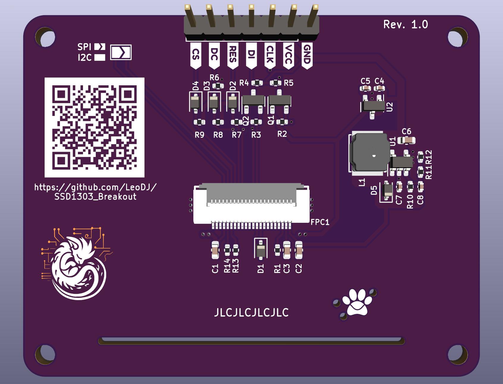
A breakout board for a specific SSD1303 OLED display.
Optimized for low-cost PCB assembly services from a specific chinese manufacturer with blue logo.
You can preview the PCB using the amazing KiCanvas. (Or the schematic if I forget to update the PDF ^^' )
| Pin | Function |
|---|---|
| GND | GND |
| VCC | 3.3 - 5 V (up to ~250mA1) |
| CLK | SPI: SCK I²C: SCL |
| DI | SPI: MOSI I²C: SDA |
| RES | Reset (active low) |
| DC | SPI: data/command line I²C: address. 0: 0x3C / 1: 0x3D (default low) |
| CS | SPI: CS |
- I/O pins are 5V tolerant
- To switch between SPI and I²C mode, you need to bridge / unbridge the solder jumper at the back (default is SPI)
- I've tried to make the pinout as compatible as possible to existing OLED modules, but there are many different variants
- In SPI mode, the "serial data out" pin of the SSD1303 (pin D2) doesn't always stay high2, as was initially measured. Thus the simple diode trick to allow both SPI and I²C mode, without needing to "keep D2 disconnected in SPI mode" as stated in the datasheet, won't work.
- Workaround: Remove D1 (below the FPC) for working SPI mode
- Fix in next revision: An additional FET in series to the D2 signal that gets activated by the solder jumper
- An additional solder jumper for I²C address would probably be nice
- In case one wants to use the breakout board on a 4-pin-only socket
- Workaround: solder a jumper wire from the DC pin/pad to the VCC pin/pad to select address
0x3D
Somehow I got a bit carried away for a relatively simple design, but otoh I've learned a lot again.
Footnotes
-
Might draw up to ~250 mA @ 3.3V with all pixels on, guesstimated.
I've measured roughly 50mA @ 12V with the highest brightness and all pixels on, so with pessimistic conversion losses around 750mW. ↩ -
It appears to shift out some kind of data, maybe from an internal register. The SSD1303 datasheet doesn't give any hint to the behaviour of pin D2 in SPI mode, except to keep it disconnected.
Over time the value that gets shifted out accumulates 1 bits. Starting at some random value with few bits set on power-up. (It probably turns into a constant high signal as soon as it reaches 0xFF, but I could only actually observe it up to 0x7F/0xF7 in my last measurement.)
When the pin is actively pulled low by the SSD1303, it interferes through the diode D1 with the actual data meant for the data input pin D1. ↩


