
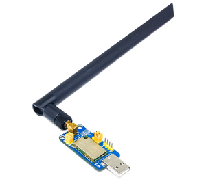
Lo-Fi combines ESP32S3 with LoRa to establish long-range wireless communication in challenging situations in addition to WiFi and BLE capabilities. With LoRa's great range and simple connectivity, you can talk with devices up to 5 km distant with ease. Device is available in three supported frequencies - 433MHz, 868MHz, and 915MHz bands for LoRa applications.
This GitHub page offers a step-by-step tutorial for using Lo-Fi.
- Device powered by powerful ESP32 S3 WROOM-1 which is having Xtensa® dual-core 32-bit LX7 microprocessor, up to 240 MHz
- Inbuilt Wi-Fi & Bluetooth LE for wireless connectivity
- Type C interface for Programming/Power
- 1.14" TFT display with resolution 135 x 240 pixels for visual interactions
- GPIO breakouts for interfacing additional peripherals
- Breadboard compatible for easy DIY breadboarding projects
- 2 separate user programmable buttons along with Reset and Boot buttons
- 3.7V Lithium Battery connector for portable use case with onboard charging option
- Use new generation LoRa spread spectrum to ensure stable communication
- LoRa supports data rate up to 62.5kbps and a longer data transmission range of up to 5 km

- (1) LoRa Module
- (2) SMA Antenna Connector
- (3) Boot Button
- (4) ESP32-S3-WROOM-1
- (5) 1.14” Display
- (6) Reset Button
- (7) Type C interface
- (8) Battery Connector
- (9) & (14) Programmable Buttons
- (10) & (13) LoRa ESP32 UART pins
- (11) & (12) Multifunctional GPIOs Breakout
-
Display interfacing with ESP32
ESP32 Display Function IO12 LCD_CLK Clock pin of SPI interface for Display IO11 LCD_DIN MOSI (Master OUT Slave IN) pin of SPI interface IO10 LCD_CS Chip Select pin of SPI interface IO13 LCD_DC Data/Command (MISO) pin of SPI interface IO14 LCD_RST Display Reset pin IO5 BL Backlight of display -
ESP32 and LoRa Module interfacing
ESP32 LoRa Module Function IO18/U1RXD LO_TX UART Communication Pin IO17/U1TXD LO_RX UART Communication Pin IO47 M0 Mode selection pin IO48 M1 Mode selection pin Note: There is option to use LoRa Tx and Rx pin either standalone or with ESP32. Default jumper is provided so LoRa is connected with ESP32. If you want to use LoRa standalone with any USB to TTL converter, then remove jumpers from L_RX-E_TX and L_TX-E_RX header pins.
-
ESP32 and Buttons interfacing
ESP32 Button Function IO7 BT1 Programmable button IO6 BT2 Programmable button IO0 BOOT Boot button
-
Download Arduino IDE from official site and install into your system. We have use Arduino IDE 1.8.19
-
Once installation done will add ESP32 S3 board support into IDE, for this first you need to add below link into preference:
https://raw.githubusercontent.com/espressif/arduino-esp32/gh-pages/package_esp32_index.jsonSelect File > Preference, and add link as show in below image,

-
Now will install ESP32 based boards as shown in below image,

-
Once done, keeping default settings select the ESP32S3 Dev Module with suitable com port (may be different in your case) as shown below,


-
Download library zip file provided here in github.
-
Extract and copy files inside Document > Arduino > Libraries folder. Make sure to restart Arduino IDE whenever you update or add any libraries.


- At this step you are all set to test codes, for easy getting started we have provided various demo example codes in github which you can download and try.
- Open one example code in Arduino and make sure you have selected correct board with suitable com port, click on upload button to transfer code on ESP32 of Lo-Fi.

- Checkout other examples below and build your own custom program codes using those references.

Checkout below demo examples code for reference getting started,
- Example 1 : Display Demo code
- Example 2 : Send Data from ESP32 over LoRa
- Example 3 : Receive Data from other LoRa Device
Now you are ready to try out your own codes, Happy Coding!
-
Follow below connection to interface LoRa Module with USB to TTL converter, make sure to remove jumpers

USB to TTL Lo-Fi Function 5V 5V Positive Supply GND GND Ground TXD L_RX UART Connection RXD L_TX UART Connection For Demo one we are using CH340 USB to TTL converter available here.
Note: Do cross connection of UART pins if module won't respond, some TTL converter follow opposite lines at TXD and RXD positions.
-
Once the LoRa Module and USB-TTL converter are connected, attach the converter to the USB port of the computer or laptop and check your COM Port in device manager.

If you don't have CH340 driver installed in PC/laptop, then checkout CH340 Driver Installation Manual Guide.
-
So, now you are ready to use LoRa module standalone with software. To decide various modes of LoRa module use example Mode Setup. Here you can set M0 and M1 values to change modes.
-
There are four operating modes, which are set by M1 and M0
Mode(0-3) M1 M0 0 Normal 0 0 1 WOR Mode 0 1 2 Configuration 1 0 3 Deep sleep 1 1
-
Refer Manual for more details of Operating Modes
-
Follow below guide line for LoRa module configuration using GUI application


Step 1: Connect LoRa to TTL converter as shown in above step. Download and open lora GUI application for windows available in github here


Step 6: Write the values which you need to configure, for eg: i configure channel and baudrate, after that press write button

How to Set corresponding frequency:
-> For changing frequency using Software for 868MHz & 915MHz LoRa module:

Frequency = 850.125MHz + CH*1MHz

0-83 total of 84 Channel available

So, when 5 selected Frequency = 850.125MHz + 5*1MHz Frequency = 855.125MHz

-> For Changing Frequency using Software for 433MHz LoRa Module: Frequency = 410.125MHz + CH*1MHz

0-83 total of 84 Channel available

So, when 5 selected Frequency = 410.125MHz + 5*1MHz Frequency = 415.125MHz


- Schematic
- Hardware Files
- Step File
- Getting Started with ESP32 in Arduino
- ESP32 S3 Hardware Reference
- ESP32 S3 WROOM 1 Datasheet
- Arduino IDE 1 overview

This is open source product. Kindly check LICENSE.md file for more information.
Please contact support@sb-components.co.uk for technical support.