PSoC™ 4: MSC self-capacitance slider tuning
This code example demonstrates how to use the CAPSENSE™ middleware to detect a finger touch position on a self-capacitance-based slider widget in PSoC™ 4 devices with multi sense converter (MSC).
In addition, this code example also explains how to manually tune the self-capacitance-based slider for optimum performance with respect to parameters such as reliability, power consumption, response time, and linearity using the CSD-RM sensing technique and CAPSENSE™ tuner GUI. Here, capacitive sigma-delta (CSD) represents the self-capacitance sensing technique and RM represents the ratiometric method.
Provide feedback on this code example.
Requirements
- ModusToolbox™ software v3.1 or later (tested with v3.1)
- Board support package (BSP) minimum required version: 3.0.0
- Programming language: C
- Associated parts: PSoC™ 4100S Max
Supported toolchains (make variable 'TOOLCHAIN')
- GNU Arm® embedded compiler v11.3.1 (
GCC_ARM) - Default value ofTOOLCHAIN - Arm® compiler v6.16 (
ARM) - IAR C/C++ compiler v9.30.1 (
IAR)
Supported kits (make variable 'TARGET')
- PSoC™ 4100S Max Pioneer Kit (
CY8CKIT-041S-MAX) - Default value ofTARGET
Hardware setup
This example uses the board's default configuration. See the kit user guide to ensure that the board is configured correctly to VDDA at 5 V (J10 should be at positions 1 and 2). If you are using the code example at a VDDA voltage other than 5 V, ensure to set up the device power voltages correctly for the proper operation of the device power domains. See Steps to setup the VDDA supply voltage in Device Configurator for more details.
Software setup
This example requires no additional software or tools.
Using the code example
Create the project and open it using one of the following:
In Eclipse IDE for ModusToolbox™ software
-
Click the New Application link in the Quick Panel (or, use File > New > ModusToolbox™ Application). This launches the Project Creator tool.
-
Pick a kit supported by the code example from the list shown in the Project Creator - Choose Board Support Package (BSP) dialog.
When you select a supported kit, the example is reconfigured automatically to work with the kit. To work with a different supported kit later, use the Library Manager to choose the BSP for the supported kit. You can use the Library Manager to select or update the BSP and firmware libraries used in this application. To access the Library Manager, click the link from the Quick Panel.
You can also just start the application creation process again and select a different kit.
If you want to use the application for a kit not listed here, you may need to update the source files. If the kit does not have the required resources, the application may not work.
-
In the Project Creator - Select Application dialog, choose the example by enabling the checkbox.
-
(Optional) Change the suggested New Application Name.
-
The Application(s) Root Path defaults to the Eclipse workspace which is usually the desired location for the application. If you want to store the application in a different location, you can change the Application(s) Root Path value. Applications that share libraries should be in the same root path.
-
Click Create to complete the application creation process.
For more details, see the Eclipse IDE for ModusToolbox™ software user guide (locally available at {ModusToolbox™ software install directory}/docs_{version}/mt_ide_user_guide.pdf).
In command-line interface (CLI)
ModusToolbox™ software provides the Project Creator as both a GUI tool and the command line tool, "project-creator-cli". The CLI tool can be used to create applications from a CLI terminal or from within batch files or shell scripts. This tool is available in the {ModusToolbox™ software install directory}/tools_{version}/project-creator/ directory.
Use a CLI terminal to invoke the "project-creator-cli" tool. On Windows, use the command line "modus-shell" program provided in the ModusToolbox™ software installation instead of a standard Windows command-line application. This shell provides access to all ModusToolbox™ software tools. You can access it by typing modus-shell in the search box in the Windows menu. In Linux and macOS, you can use any terminal application.
The "project-creator-cli" tool has the following arguments:
| Argument | Description | Required/optional |
|---|---|---|
--board-id |
Defined in the <id> field of the BSP manifest |
Required |
--app-id |
Defined in the <id> field of the CE manifest |
Required |
--target-dir |
Specify the directory in which the application is to be created if you prefer not to use the default current working directory | Optional |
--user-app-name |
Specify the name of the application if you prefer to have a name other than the example's default name | Optional |
The following example clones the "CAPSENSE™ MSC CSD slider tuning" application with the desired name "MSCCSDSliderTuning" configured for the CY8CKIT-041S-MAX BSP into the specified working directory, C:/mtb_projects:
project-creator-cli --board-id CY8CKIT-041S-MAX --app-id mtb-example-psoc4-msc-capsense-csd-slider-tuning --user-app-name MSCCSDSliderTuning --target-dir "C:/mtb_projects"
Note: The project-creator-cli tool uses the git clone and make getlibs commands to fetch the repository and import the required libraries. For details, see the "Project creator tools" section of the ModusToolbox™ software user guide (locally available at {ModusToolbox™ software install directory}/docs_{version}/mtb_user_guide.pdf).
To work with a different supported kit later, use the Library Manager to choose the BSP for the supported kit. You can invoke the Library Manager GUI tool from the terminal using make library-manager command or use the Library Manager CLI tool "library-manager-cli" to change the BSP.
The "library-manager-cli" tool has the following arguments:
| Argument | Description | Required/optional |
|---|---|---|
--add-bsp-name |
Name of the BSP that should be added to the application | Required |
--set-active-bsp |
Name of the BSP that should be as active BSP for the application | Required |
--add-bsp-version |
Specify the version of the BSP that should be added to the application if you do not wish to use the latest from manifest | Optional |
--add-bsp-location |
Specify the location of the BSP (local/shared) if you prefer to add the BSP in a shared path | Optional |
Following example adds the CY8CKIT-041S-MAX BSP to the already created application and makes it the active BSP for the app:
~/ModusToolbox/tools_{version}/library-manager/library-manager-cli --project "C:/mtb_projects/MSCCSDSliderTuning" --add-bsp-name CY8CKIT-041S-MAX --add-bsp-version "latest-v4.X" --add-bsp-location "local"

~/ModusToolbox/tools_{version}/library-manager/library-manager-cli --project "C:/mtb_projects/MSCCSDSliderTuning" --set-active-bsp APP_CY8CKIT-041S-MAX
In third-party IDEs
Use one of the following options:
-
Use the standalone Project Creator tool:
-
Launch Project Creator from the Windows Start menu or from {ModusToolbox™ software install directory}/tools_{version}/project-creator/project-creator.exe.
-
In the initial Choose Board Support Package screen, select the BSP, and click Next.
-
In the Select Application screen, select the appropriate IDE from the Target IDE drop-down menu.
-
Click Create and follow the instructions printed in the bottom pane to import or open the exported project in the respective IDE.
-
-
Use command-line interface (CLI):
-
Follow the instructions from the In command-line interface (CLI) section to create the application.
-
Export the application to a supported IDE using the
make <ide>command. -
Follow the instructions displayed in the terminal to create or import the application as an IDE project.
-
For a list of supported IDEs and more details, see the "Exporting to IDEs" section of the ModusToolbox™ software user guide (locally available at {ModusToolbox™ software install directory}/docs_{version}/mtb_user_guide.pdf).
Operation
-
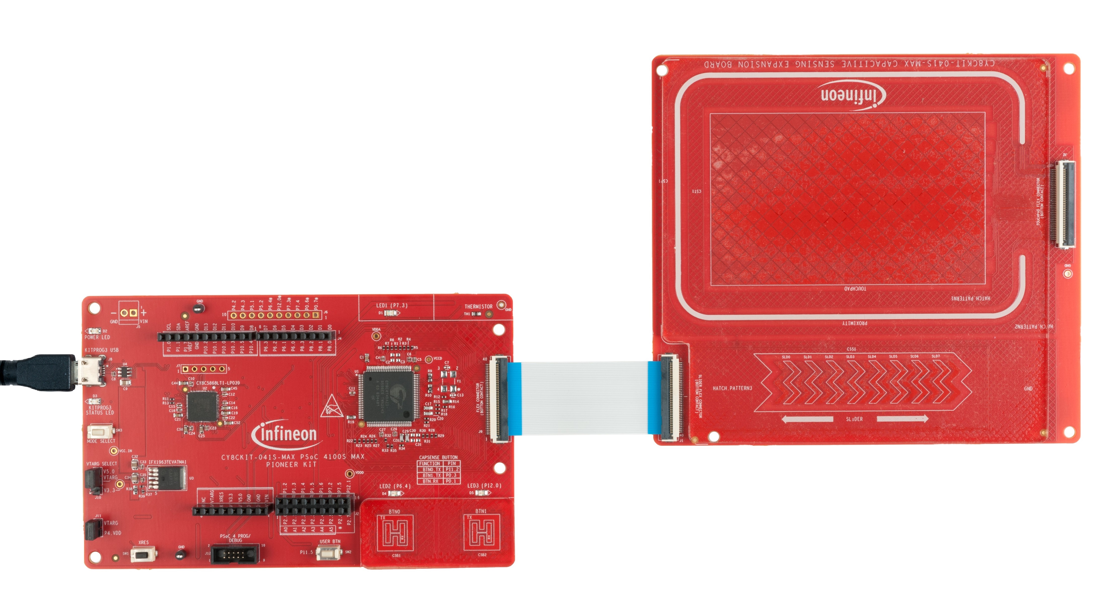
Connect the FFC cable between J9 on the PSoC™ 4100S Max Pioneer Board and J1 on the capacitive sensing expansion board. Connect a USB 2.0 Type-A to Micro-B cable on J8 (USB Micro-B connector) as shown in Figure 1 to power the device.
Figure 1. Connecting the CY8CKIT-041S-MAX kit with a capacitive sensing expansion board to a PC
-
Program the board using one of the following:
Using Eclipse IDE for ModusToolbox™ software
-
Select the application project in the Project Explorer.
-
In the Quick Panel, scroll down, and click <Application Name> Program (KitProg3_MiniProg4).
Using CLI
From the terminal, execute the
make programcommand to build and program the application using the default toolchain to the default target. The default toolchain is specified in the application's Makefile but you can override this value manually:make program TOOLCHAIN=<toolchain>Example:
make program TOOLCHAIN=GCC_ARM -
-
After programming, the application starts automatically.
-
To test the application, slide your finger over the CAPSENSE™ Slider and notice that the user LED (LED1) turns ON when touched and turns OFF when the finger is lifted.
-
You can also monitor the CAPSENSE™ data using the CAPSENSE™ tuner application as follows:

Monitor data using the CAPSENSE™ tuner
-
Open the CAPSENSE™ tuner from the Tools section in the IDE Quick Panel.
You can also run the CAPSENSE™ tuner application standalone from {ModusToolbox™ software install directory}/ModusToolbox/tools_{version}/capsense-configurator/capsense-tuner. In this case, after opening the application; select File > Open and open the design.cycapsense file of the respective application, which is in the {Application root directory}/bsps/TARGET_<BSP-NAME>/config folder.
See the ModusToolbox™ software user guide (locally available at {ModusToolbox™ install directory}/docs_{version}/mtb_user_guide.pdf) for options to open the CAPSENSE™ tuner application using the CLI.
-
Ensure that the kit is in CMSIS-DAP bulk mode (KitProg3 status LED is ON and not blinking). See Firmware-loader to learn how to update the firmware and switch modes in KitProg3.
-
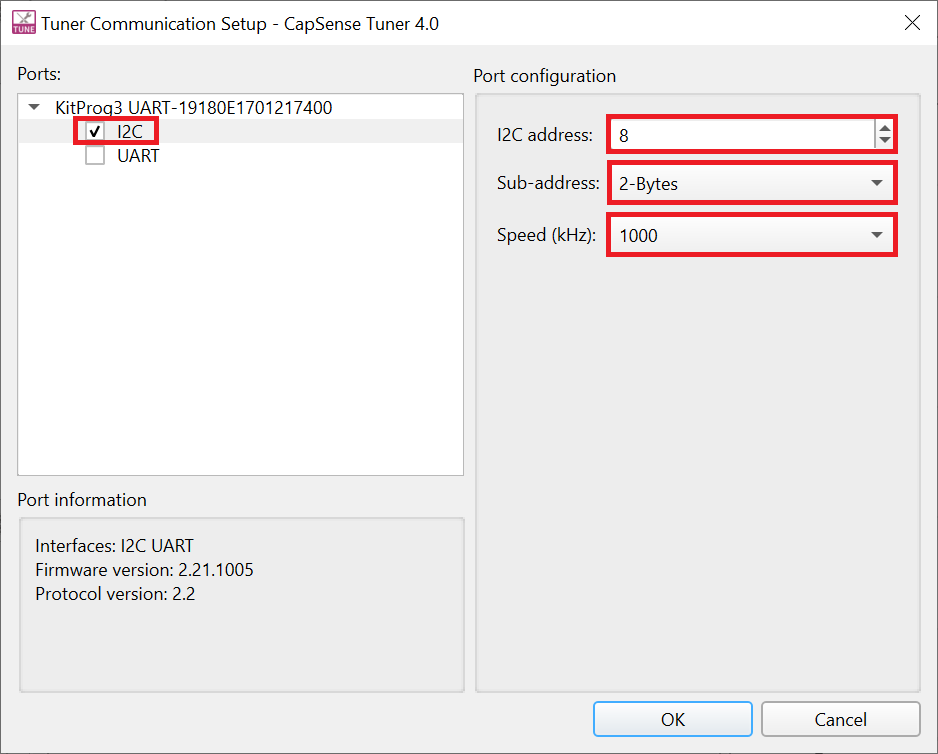
In the tuner application, click the Tuner Communication Setup or select Tools > Tuner Communication Setup and select the I2C checkbox under KitProg3 and configure the parameters as follows:
- I2C address: 8
- Sub-address: 2-Bytes
- Speed (kHz): 1000
These are the same values set in the EZI2C resource.
Figure 2. Tuner communication setup parameters
-
Click Connect or select Communication > Connect to establish a connection.
-
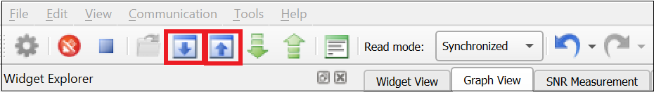
Click Start or select Communication > Start to start data streaming from the device.
The tuner displays the data from the sensor in the Widget View and Graph View tabs.
-
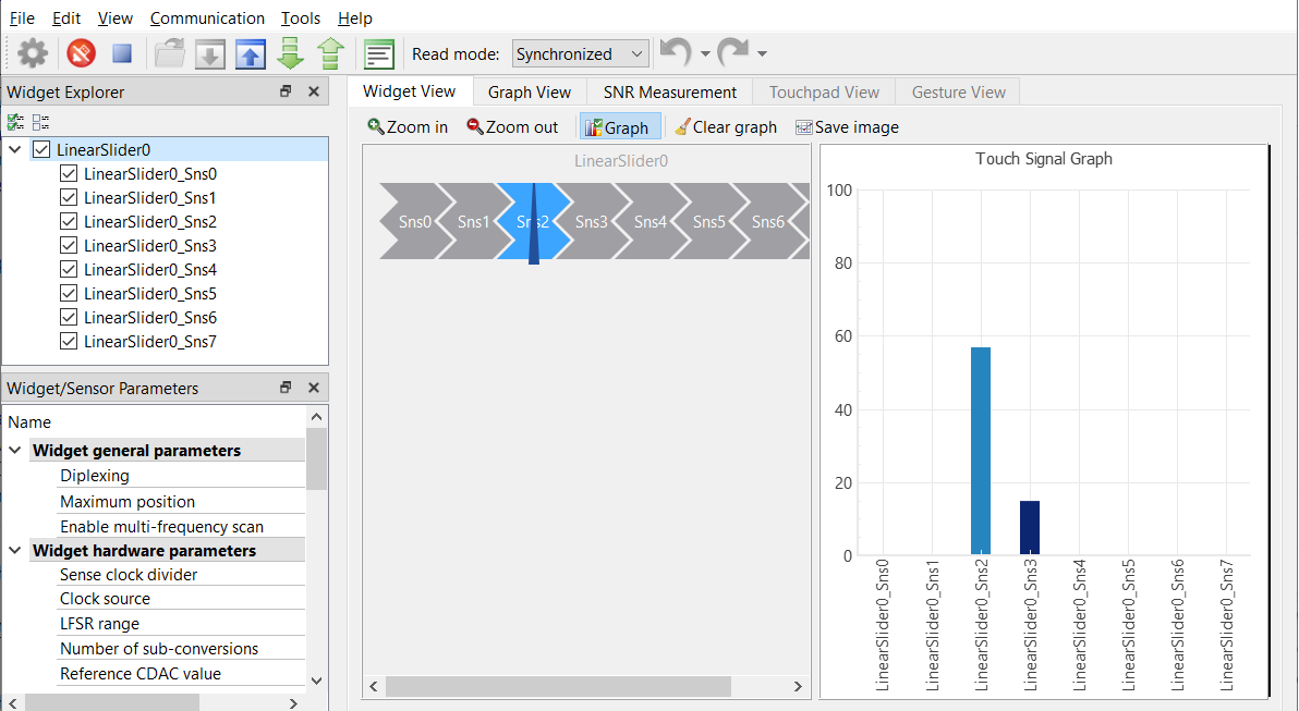
Set the Read Mode to synchronized mode. Under the Widget View tab, you can see the slider widget highlighted in blue color when you touch it.
Figure 3. Widget view of the CAPSENSE™ tuner
-
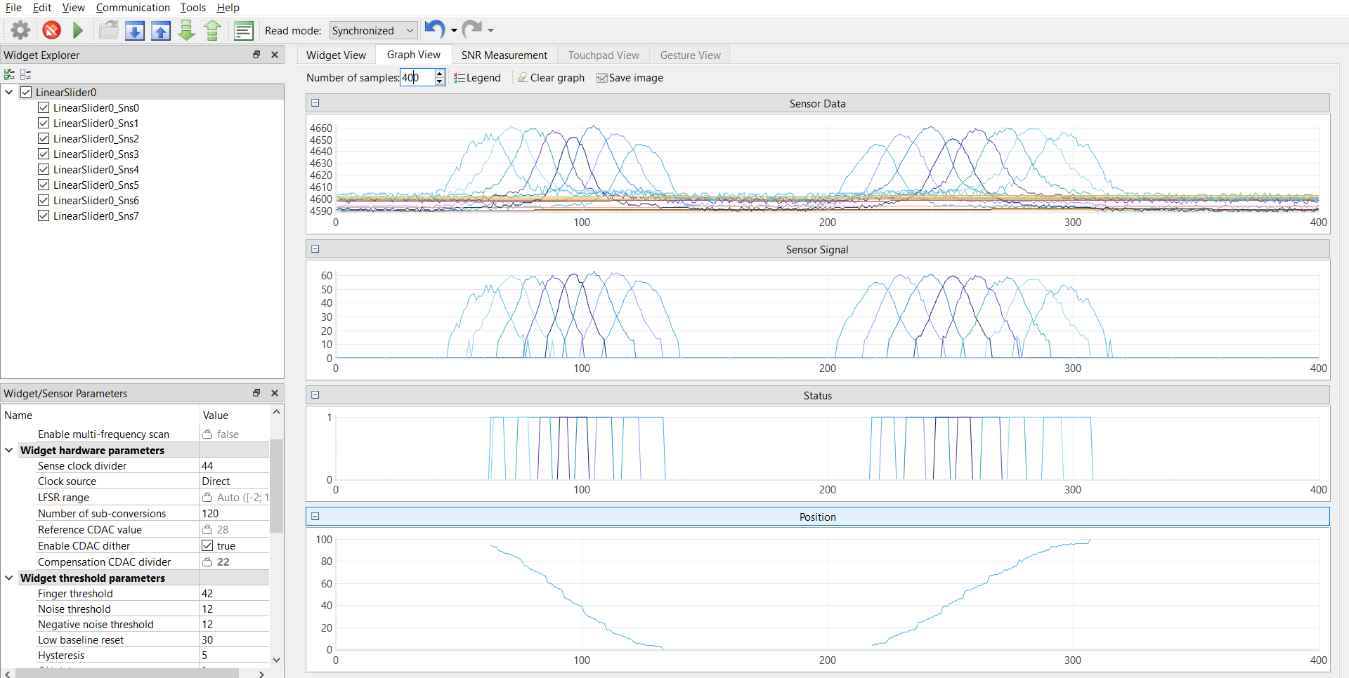
You can view the raw count, baseline, difference count, status for each sensor, and slider position in the Graph View tab. For example, to view the sensor data for sensor 0, select LinearSlider0_Sns0 under LinearSlider0.
Figure 4. Graph view of the CAPSENSE™ Tuner
-
Observe the Widget/Sensor Parameters section in the CAPSENSE™ Tuner window. Figure 16 shows the Compensation CDAC values for each slider sensor element calculated by the CAPSENSE™ resource.
-
Verify that the SNR is greater than 5:1 by following the steps given in Stage 4 starting with Step 6.
Non-reporting of false touches and the linearity of the position graph indicate proper tuning.
Note: Enhance the slider performance further by configuring the board to connect the Hatch pattern to Shield. See the kit user guide for the board connection settings. In addition, ensure to enable the Shield Signals in the CAPSENSE™ Configurator as shown in Figure 5. Retune the slider following the tuning process as given in the Tuning procedure.
Figure 5. Enabling shield signals in CAPSENSE™ Configurator


Tuning procedure
Create a custom BSP for your board
-
Create a custom BSP for your board having any device (for example, "CY8C4149AZI-S598") by following the steps given in KBA231373.
-
Open the design.modus file from {Application root directory}/bsps/TARGET_<BSP-NAME>/config folder obtained in the previous step and enable CAPSENSE™ to get design.cycapsense file. Start the CAPSENSE™ configuration from scratch as explained in the following steps.
The following steps explain the tuning procedure.
Note: See the section "Selecting CAPSENSE™ hardware parameters" in the PSoC™ 4 and PSoC™ 6 MCU CAPSENSE™ design guide to learn about the considerations for selecting each parameter value.
Figure 6. CSD slider widget tuning flow

Do the following to tune the slider:
Stage 1: Set the initial hardware parameters
-
Connect the board to your PC using the provided USB cable through the KitProg3 USB connector.
-
Launch the Device configurator tool.
You can launch the Device configurator in the Eclipse IDE for ModusToolbox™ software from the Tools section in the IDE Quick Panel.
You can also launch it in stand-alone mode from {ModusToolbox™ software install directory}/ModusToolbox/tools_{version}/device-configurator/device-configurator. In this case, after opening the application, select File > Open and open the design.modus file of the respective application, which is in the {Application root directory}/bsps/TARGET_<BSP-NAME>/config folder.
Note: If you are using the custom BSP with the empty PSoC™ 4 starter application, use {Application root directory}/bsps/TARGET_<BSP-NAME>/config folder to open the design.modus file.
-
In the CY8CKIT-041S MAX kit, the slider pins are connected to channel 0. Therefore, enable channel 0 in the Device configurator as shown in Figure 7.
Figure 7. Enable MSC channels in Device configurator
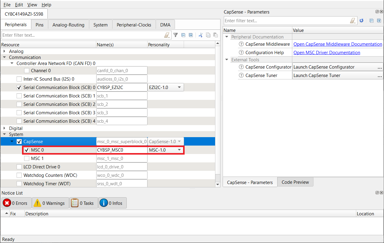
Save the changes and close the window.
-
Launch the CAPSENSE™ configurator tool.
You can launch the CAPSENSE™ configurator tool in Eclipse IDE for ModusToolbox™ from the CAPSENSE™ peripheral setting in the Device configurator, or directly from the Tools section in the IDE Quick Panel.
You can also launch it in stand-alone mode from {ModusToolbox™ software install directory}/ModusToolbox/tools_{version}/capsense-configurator/capsense-configurator. In this case, after opening the application, select File > Open and open the design.cycapsense file of the respective application, which is in the {Application root directory}/bsps/TARGET_<BSP-NAME>/config folder.
Note: If you are using the custom BSP with the empty PSoC™ 4 starter application, use {Application root directory}/bsps/TARGET_<BSP-NAME>/config folder to open the design.modus file.
See the ModusToolbox™ software CAPSENSE™ configurator tool guide for step-by-step instructions on how to configure and launch CAPSENSE™ in ModusToolbox™ software.
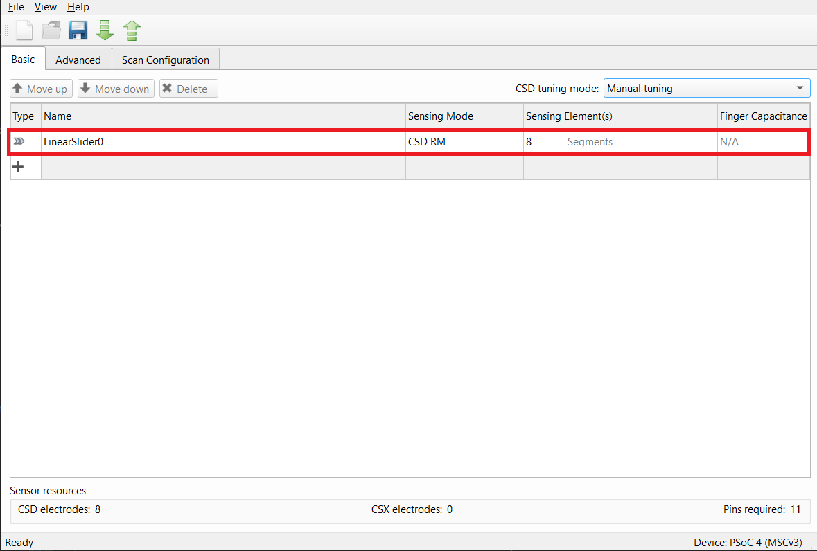
-
In the Basic tab, note that a single slider LinearSlider0 is configured as a CSD-RM (Self-cap), and the CSD tuning mode is set as Manual tuning.
Figure 8. CAPSENSE™ Configurator - Basic tab
-
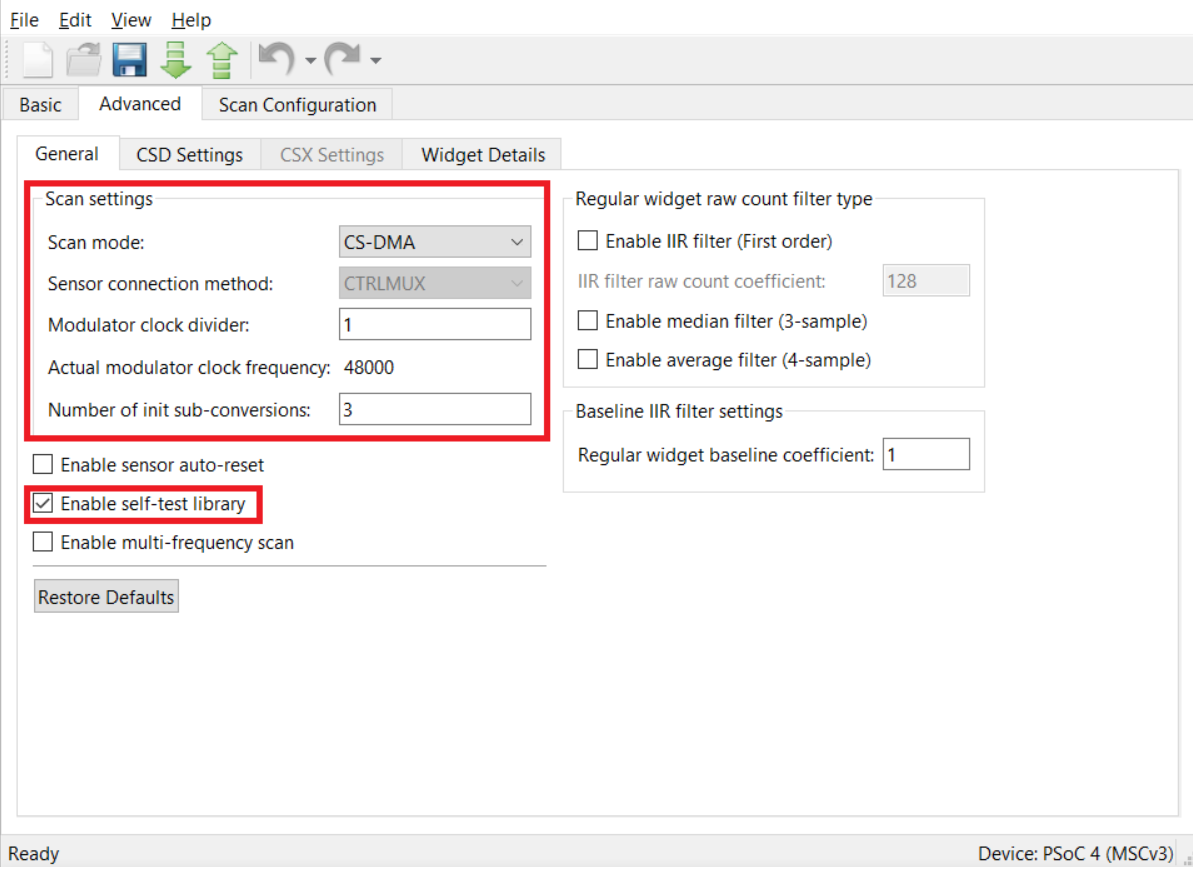
Do the following in the General tab under the Advanced tab:
- Set Scan mode as CS-DMA to enable autonomous scanning.
Automated scan using DMA helps scan multiple sensors autonomously and offload the CPU.
Ensure to do the required DMA settings in the Device Configurator as given in the KBA233869.
-
Sensor connection method is CTRLMUX by default for CS-DMA scan mode.
CTRLMUX mode allows the MSC block to control the GPIO pins and removes the need for AMUXBUS to transfer CAPSENSE™ signals between GPIO and the MSC block.
-
Set the Modulator clock divider as 1 to obtain the maximum available modulator clock frequency as recommended in the CAPSENSE™ design guide.
-
Number of init sub-conversions is set based on the hint shown when you hover over the edit box. Retain default value (will be set in Stage 3)
Note: Equation 1 is considering the default values of Cmod = 2.2 nF, Base % = 0.5 (50%), and Auto-calibration % = 0.85 (85%). If you intend to change any value, see AN85951 – PSoC™ 4 and PSoC™ 6 MCU CAPSENSE™ design guide to calculate the required number of init sub-conversions.
Equation 1. Number of init sub-conversions

Where,
VDDA = 5 V
Cs = Least self-capacitance value out of the sensors in pF (obtained in Stage 2)
-
Check the Enable self-test library selection. This is required for sensor capacitance measurement using BIST.
-
Retain the default settings for all filters. You can enable the filters later depending on the signal-to-noise ratio (SNR) requirements in Stage 5.
Filters are used to reduce the peak-to-peak noise. Use of filters results in higher scan time.
Figure 9. CAPSENSE™ configurator
-
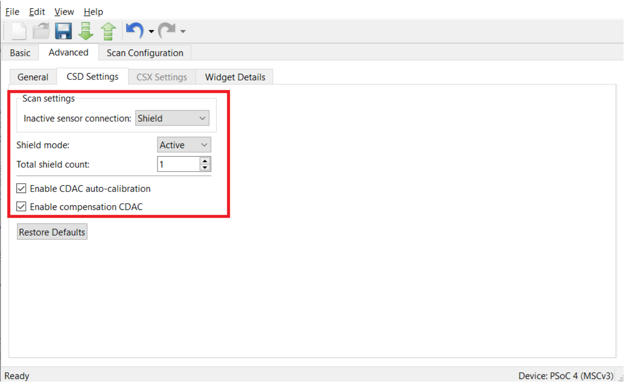
Go to the CSD settings tab and make the following changes:
- Set Inactive sensor connection as Shield.
Inactive sensors connected to Shield provide better performance in terms of SNR and Refresh rate (as the use of shield results in a reduction of sensor Cp) and can also be used if your design requires liquid tolerance.
- Set Shield mode as Active.
MSC provides active and passive shielding. Passive shielding is selected if the total Shield Cp is less than 100 pF and helps to save power. Before enabling this option, ensure that the PCB has the shield electrode.
- Set the Total shield count as 1.
The slider in the CY8CKIT-041S MAX kit is a hybrid slider that can showcase self-capacitance and mutual-capacitance-based scanning. As this code example is for self-capacitance-based slider scanning, to get the best performance, configure the slider TX electrode as a shield.
-
Select Enable CDAC auto-calibration and Enable compensation CDAC.
This helps in achieving the required CDAC calibration levels (85% of maximum count) for all sensors in the widget while maintaining the same sensitivity across the sensor elements.
Figure 10. CAPSENSE™ Configurator - CSD Settings tab under the Advanced tab
-
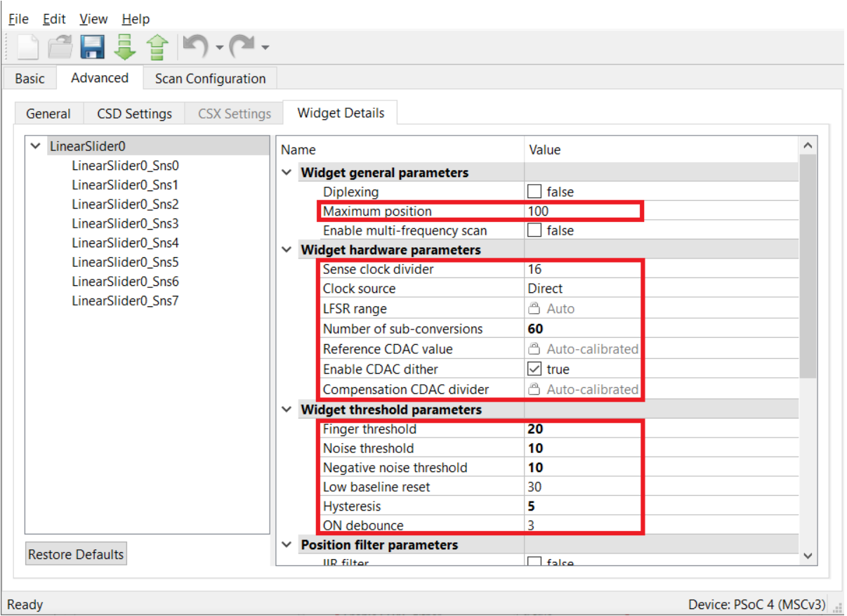
Go to the Widget Details tab. Select LinearSlider0 from the left pane and then set the following:
-
Maximum position to 100.
-
Sense clock divider: Retain the default value (it will be set in Stage 3)
-
Clock source: Direct
Note: Spread spectrum clock (SSC) or PRS clock can be used as a clock source to deal with EMI/EMC issues. The selected value should be set using the Widget Details tab in the CAPSENSE™ Configurator.
-
Number of sub-conversions: 60
60 is a good starting point to ensure a fast scan time and sufficient signal. This value will be adjusted as required in Stage 5.
-
Finger Threshold: 20
Finger Threshold is initially set to a low value allowing the Slider View to track the finger movement during tuning.
-
Noise Threshold: 10
-
Negative noise threshold: 10
-
Hysteresis: 5
This reduces the influence of the baseline on the sensor signal, which helps to get the true difference-count. Retain the default values for all other threshold parameters; these parameters are set in Stage 6.
Figure 11. CAPSENSE™ configurator - Widget details tab under the Advanced tab
-
-
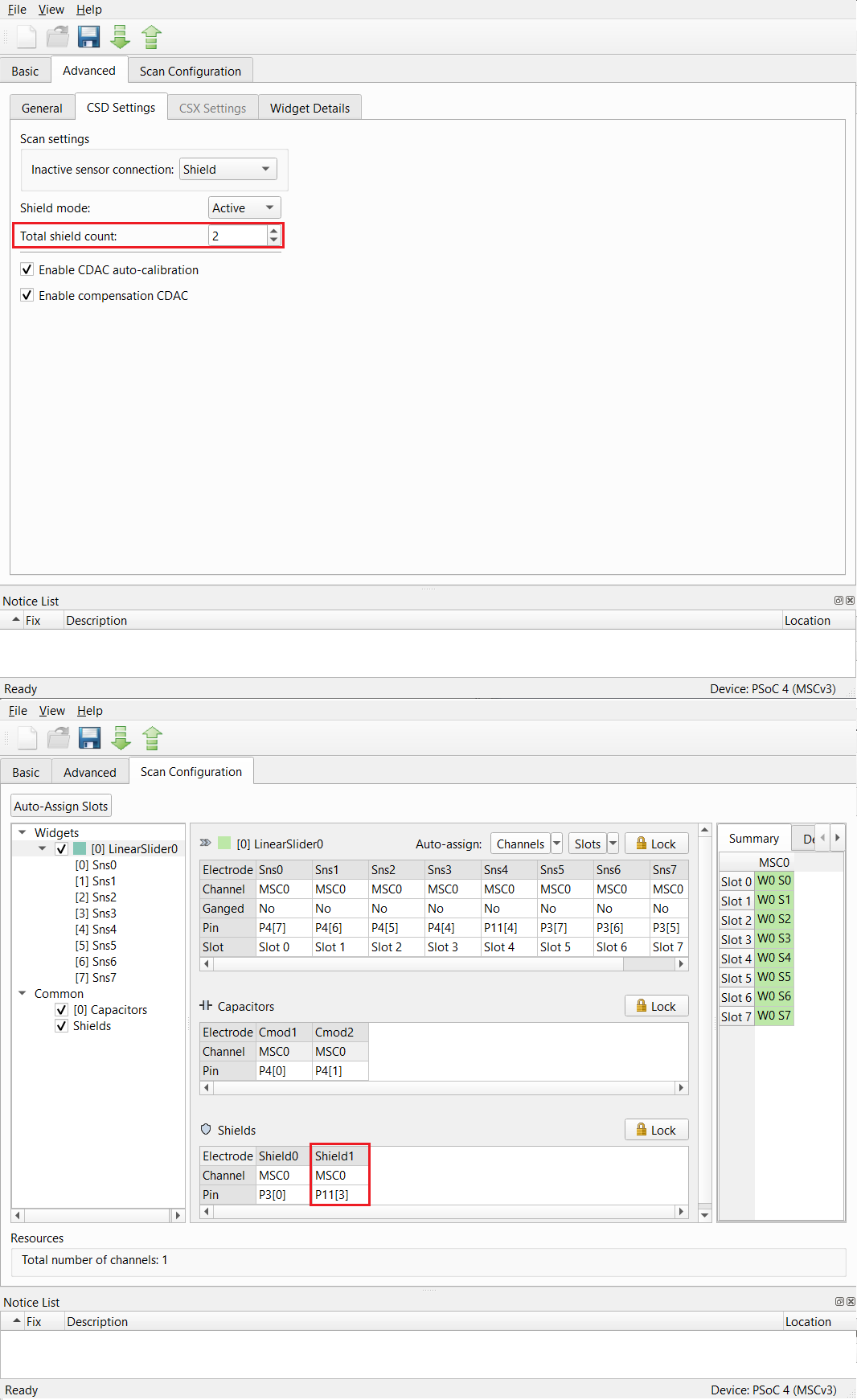
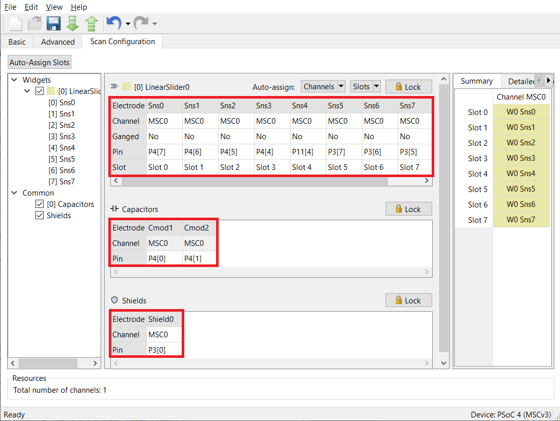
Go to the Scan Configuration tab to select the pins for sensor electrodes, Cmod, and shield. Do the following:
Set the parameters in the Scan Configuration tab as shown in Figure 12.
Figure 12. Scan Configuration
-
Configure the channel as MSC0 for all the sensor electrodes using the drop-down menu.
-
Configure pins for the electrodes using the drop-down menu.
-
Configure pins for the Cmod1 and Cmod2.
-
Configure P3[0] pin as a shield as it is the Slider TX electrode for the CY8CKIT-041S MAX Kit.
-
-
Click Save to apply the settings.


Stage 2. Measure the parasitic capacitance (Cp)
To determine the maximum sensor Cp, measure the Cp of each sensor element of the slider, between the sensor electrode (sensor pin) and device ground, using an LCR meter or using BIST function or by back-calculating for Cs (sensor capacitance) using the Raw Count equation.
See the Equation: CSD-RM raw count in PSoC™ 4 and PSoC™ 6 MCU CAPSENSE™ design guide for the Raw Count equation.
Measure sensor and shield capacitances using BIST:
Use the Cy_CapSense_MeasureCapacitanceSensorElectrode() BIST function to measure the parasitic capacitance (Cp) of each Slider sensor to determine the maximum Cp out of all the sensors.
Use the Cy_CapSense_MeasureCapacitanceShieldElectrode() function to measure the total Shield capacitance (Csh) of the Slider.
Note: Use the Cy_CapSense_SetInactiveElectrodeState() function to set the inactive electrode state to "Shield" before calling the above functions, as these functions use "Ground" as the default inactive electrode state.
If you are using the empty PSoC™ 4 starter application, you can copy the respective source code from this example’s main.c file to the main.c file of the application project. If you are using this code example, the required files are already in the application.
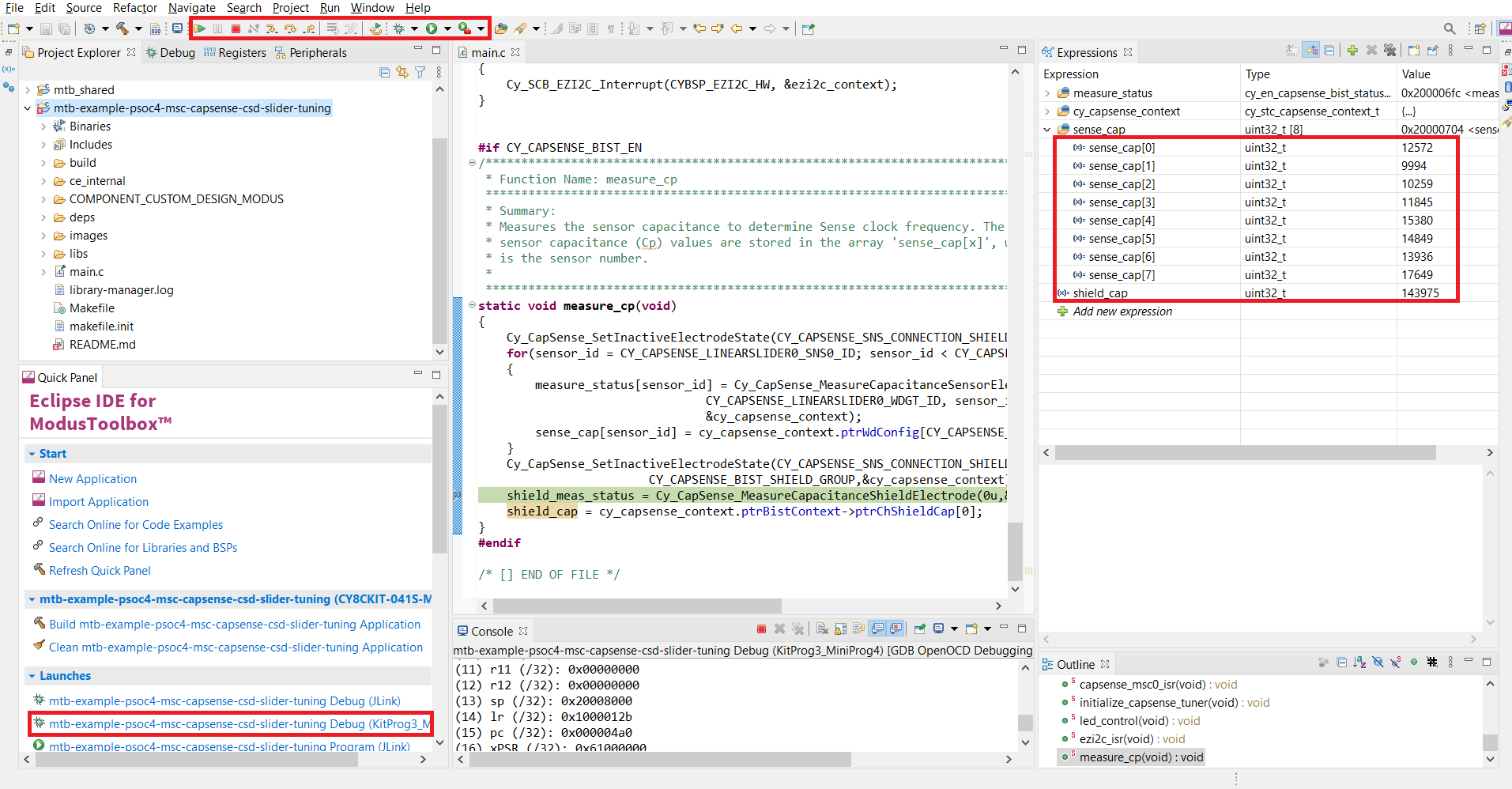
Do the following to determine the Cp values in debug mode:
-
Program the board in debug mode.
In the IDE, use the <Application Name> Debug (KitProg3) configuration in the Quick Panel.
For more details, see the "Program and debug" section in the Eclipse IDE for ModusToolbox™ software user guide: {ModusToolbox™ software install directory}/docs_{version}/mtb_ide_user_guide.pdf.
-
Place a breakpoint after the capacitance measurement.
-
In the Expressions window, add the Cp measurement variable array:
sense_cap[].Read the status of the measurement through the return value of the function in the Expressions window.
-
Click the Resume button (green arrow) to reach the breakpoint.
Note that the function return values read
CY_CAPSENSE_BIST_SUCCESS_Eand the measurement variables provide the capacitance of the sensor elements in femtofarads.Figure 13. Sensor capacitance measurement values obtained in debug mode
-
Click the Terminate button (red box) to exit debug mode.
Table 1. Cp values obtained for CY8CKIT-041S-MAX kit
Kit Parasitic capacitance (CP) in pF Sns0 13 Sns1 10 Sns2 10 Sns3 12 Sns4 15 Sns5 15 Sns6 14 Sns7 18 Shield 144

Stage 3. Calculate the sense clock frequency and init sub-conversions
-
Calculate the sense clock frequencies using Equation 2.
Equation 2. Max sense clock frequency

Where,
-
CP is the maximum parasitic capacitance of the sensor electrode.
-
RSeriesTotal is the maximum total series resistance, which includes the 525-ohm (for CTRLMUX mode) internal resistance, the external series resistance (in CY8CKIT-041S MAX, it is 2 kilo-ohms), and the trace resistance. Include the trace resistance if high-resistive material such as ITO or conductive ink is used. The external resistor is connected between the sensor pad and the device pin to reduce the radiated emission. ESD protection is built into the device.
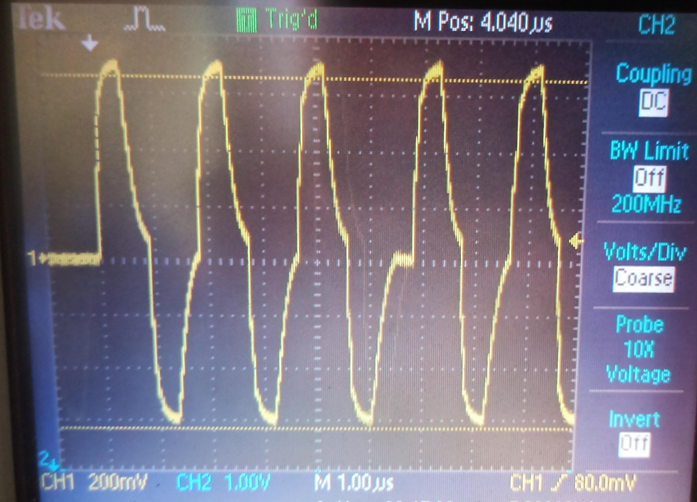
Note 1: If an LCR meter is not available, set an initial sense clock divider value and look at the charge and discharge waveforms of the sensor electrode and iteratively change the divider, and set a maximum frequency such that it completely charges and discharges in each phase of the MSC CSD-RM sensing method.
Note 2: The maximum frequency set should charge and discharge the sensor completely, which you can verify using an oscilloscope and an active probe. To view the charging and discharging waveforms of the sensor, keep the probe at the sensors (or as close as possible to the sensors), and not at the pins or resistor using active probes.
Note 3: Figure 14 shows the waveforms when the sensors are not fully charging and discharging:
Figure 14. Sensor not fully charging and discharging
-
-
Ensure that the following conditions are also satisfied when selecting the sense clock frequency and CDAC compensation divider:
-
The auto-calibrated CDAC and compensation CDAC value should lie in the valid range for the selected sense clock divider and CDAC compensation divider. Verify this after the initial hardware parameters are loaded into the device. See Step 5 (Ensure that the auto-calibrated CDAC is within the recommended range) of Stage 4 for details.
-
If you are explicitly using the PRS or SSCx clock source to lower electromagnetic interference, select the sense clock frequency that meets the conditions mentioned in the ModusToolbox™ software CAPSENSE™ Configurator tool guide in addition to the above conditions. PRS and SSCx techniques spread the frequency across a range. The maximum frequency set should charge and discharge the sensor completely, which you can verify using an oscilloscope and an active probe.
Table 2. Sense clock frequency settings
Kit RSeriesTotal (Ω) for sensors RSeriesTotal (Ω) for shield Maximum sensor Cp (pF) Total shield Csh (pF) Maximum sense clock frequency (kHz) based on sensor Cp Maximum sense clock frequency (kHz) based on shield Csh Actual column sense clock frequency (kHz) CY8CKIT-041S-MAX 2525 250 18 144 1100 1389 1091 -


Note 1: All the unused sensor electrodes are ganged to form the shield electrode. RSeriesTotal (Ω) for the shield is obtained by a parallel combination of the resistances (external + internal) of each unused sensor electrode (i.e., configured as "Shield").
Total resistance on each unused sensor line: 2000 + 250 = 2250
Number of unused sensors: 9
Therefore, parallel resistance obtained: 2250/9 = 250 Ω
Total shield capacitance Csh (per channel) is calculated as a parallel combination of individual parasitic capacitances of the shield electrodes.
**Note 2:** Choose the actual sense clock frequency value such that the divider is divisible by 4 to have all 4 scan phases for equal durations.
**Note 3:** The sense clock divider value, as given by **Equation 3**, is obtained by dividing HFCLK (48 MHz) by **Maximum sense clock frequency (kHz)** calculated in **Stage 3** (see **Table 2**) and choosing the nearest ceiling sense clock divider option in the Configurator.
**Equation 3. Sense clock divider**

In this case, sense clock divider = 48000/1091 = 44.
Set the calculated value using Step 8 in Stage 1, which ensures the maximum possible sense clock frequency (for good gain) while allowing the sensor capacitance to fully charge and discharge in each phase of the MSC CSD sensing method. In addition, ensure that the shield waveform is probed and satisfies the condition given in the section Shield electrode tuning theory in the CAPSENSE™ design guide.
- Calculate and set the Number of init sub-conversions using Step 6 in Stage 1.
Stage 4. Obtain cross-over point and noise
-
Program the board.
-
Check the calibration pass/fail status from the return value of the
Cy_CapSense_Enable()function. -
Launch the CAPSENSE™ Tuner to monitor the CAPSENSE™ data and for CAPSENSE™ parameter tuning and SNR measurement.
See the CAPSENSE™ Tuner guide for step-by-step instructions on how to launch and configure the CAPSENSE™ Tuner in ModusToolbox™ software.
-
Ensure that the auto-calibrated CDAC is in the recommended range.
As mentioned in Step 5, tune the sense clock divider to bring the CDAC values to the recommended range in this step.
- Click LinearSlider0 in the Widget Explorer to view reference CDAC value in the Sensor Parameters window as shown in Figure 16.
- Click each sensor element, for instance, LinearSlider0_Sns0 in the Widget Explorer to view the compensation CDAC in the Sensor Parameters window as shown in Figure 16.
- If the reference CDAC values are above 20/(CDAC compensation divider), ignore Step 5.
-
Fine-tune the sense clock divider to bring the CDAC value into the required range.
From the Raw Count equation (given in the PSoC™ 4: MSC CAPSENSE™ CSD button tuning code example), it is evident that increasing the sense clock divider will decrease the reference CDAC value for a given calibration percent and vice-versa.
-
If the reference CDAC value is below/above the recommended range, increase/decrease the sense clock divider in the Widget Hardware Parameters window.
-
Click To Device to apply the changes to the device as shown in Figure 15.
Figure 15. Apply changes to device

-
Additionally, click each sensor element, for instance, LinearSlider0_Sns0 in the Widget Explorer.
-
Observe the Compensation CDAC value in the Sensing Parameters section of the Widget/Sensor Parameters window.
-
Repeat Steps 1 to 4 until you obtain all CDAC values in the recommended range.
Figure 16. CDAC value
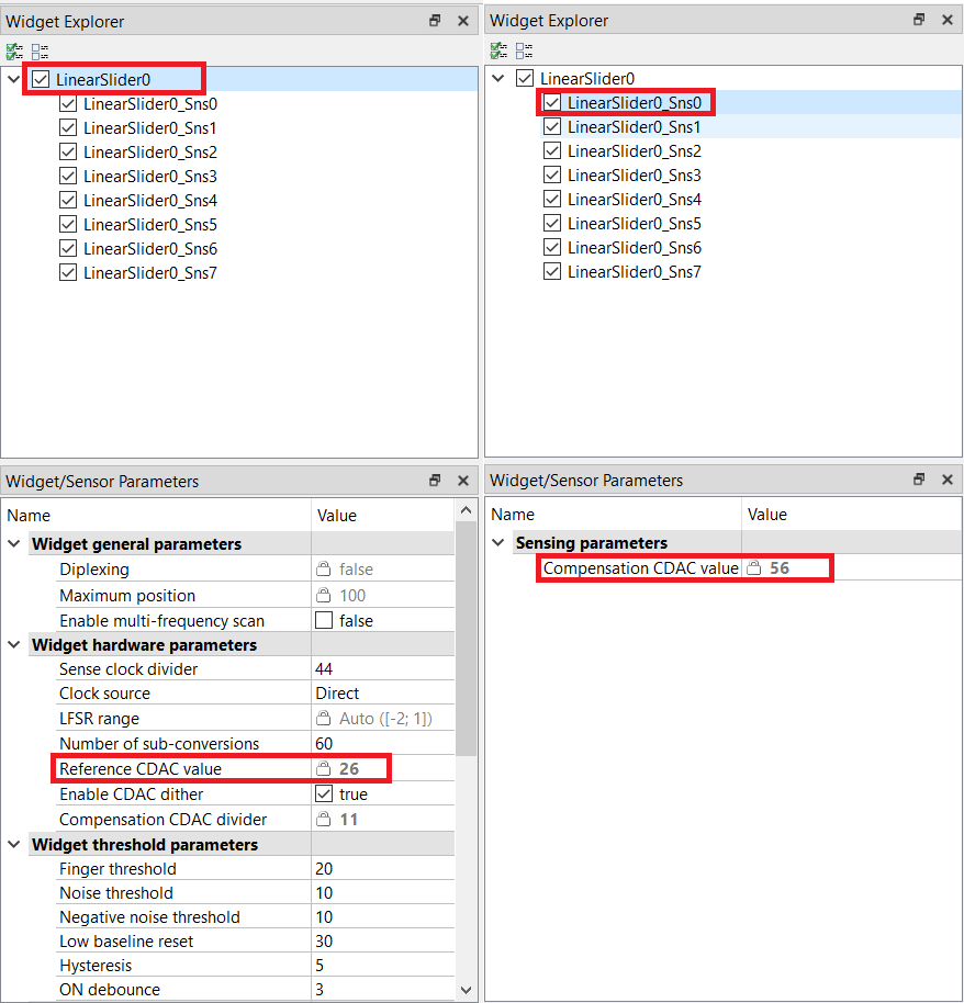
Note: If the CDAC values are still not in the required range, reduce the modulator clock frequency to 24 MHz.
As Figure 16 shows, CDAC values are in the recommended range. You can leave the sense clock divider to the value as shown in Step 8 of Stage 3.
-
-
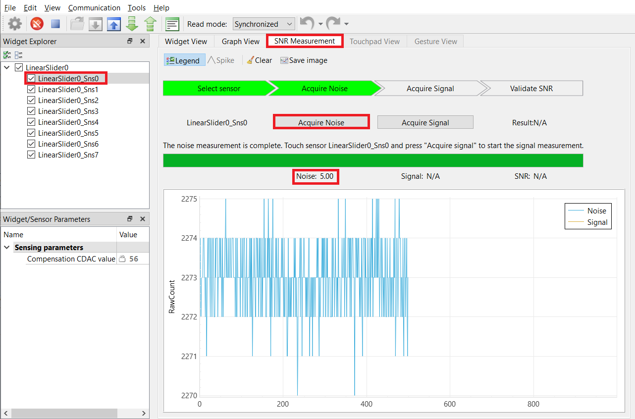
Capture and note the peak-to-peak noise of each segment of the slider.
-
From the Widget Explorer section, select a sensor (for example, LinearSlider0_Sns0).
-
Go to the SNR Measurement tab and click Acquire Noise to capture peak-to-peak noise as shown in Figure 17.
Figure 17. Noise obtained on the SNR Measurement tab in Tuner window
-
Repeat Steps 1 and 2 for all the sensors to capture peak-to-peak noise.
Table 3. Peak-to-peak noise obtained for each segment
Slider segment Peak-to-peak noise (CY8CKIT-041S-MAX) SNS0 5 SNS1 5 SNS2 4 SNS3 4 SNS4 5 SNS5 6 SNS6 6 SNS7 7
-


-
Use a grounded metal finger (typically 8 mm or 9 mm) and swipe it slowly at a constant speed from the start to the end of the slider.
-
Go to the Graph View tab to view a graph similar to Figure 18.
-
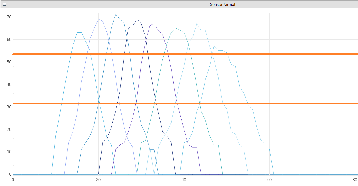
Get the upper crossover point (UCP) and lower crossover point (LCP) as shown in Figure 19.
Figure 18. Difference count (delta) vs. finger position
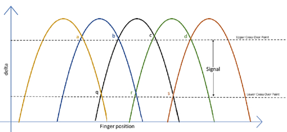
Sensor signal values at points a, b, c, and d are expected to be at approximately the same level. If the values are slightly different, consider the lowest value as the UCP.
Sensor signal values at points q, r, and s are expected to be at approximately the same level. If the values are slightly different, consider the lowest value as the LCP.
Figure 19. Sensor signal (difference counts) displayed in the Graph View tab
-


Stage 5. Use the CAPSENSE™ Tuner to fine-tune sensitivity for 5:1 SNR
The CAPSENSE™ system may be required to work reliably in adverse conditions such as a noisy environment. Tune the slider segments with SNR > 5:1 to avoid triggering false touches and ensure that all intended touches are registered in these adverse conditions.
-
Ensure that all UCPs meet at least 5:1 SNR (using Equation 4) and all LCPs are greater than twice the peak-to-peak noise for all slider segments.
In the CAPSENSE™ Tuner window, increase the Number of sub-conversions (located in the Widget/Sensor Parameters section, under Widget Hardware Parameters) by 10 until you achieve at least 5:1 SNR.
Equation 4. SNR equation

Note: Ensure that the Number of sub-conversions (Nsub) does not exceed the maximum limit and saturate the raw count.
Use Equation 5 to calculate the maximum number of sub-conversions:
Equation 5. Number of sub-conversions

Max Nsub = 2^16/44 = 65536/44 = 1489 (16-bit counter)
Nsub is also tuned to satisfy the refresh rate that is required.
Equation 6. Scan time

Note: Total scan time is equal to the sum of the initialization time and the scan time given by Equation 6.
-
After changing the Number of sub-conversions, click Apply to Device to send the setting to the device. The change is reflected in the graphs.
Note: The Apply to Device option is enabled only when the Number of sub-conversions is changed.


Stage 6. Use CAPSENSE™ Tuner to tune threshold parameters
After confirming that your design meets the timing parameters and the SNR is greater than 5:1, set your threshold parameters as follows:
- Set the recommended threshold values for the Slider widget using the LCP and UCP obtained in Stage 5:
- Finger Threshold – 80% of UCP
- Noise Threshold – Minimum (twice the peak-to-peak noise, LCP)
- Negative Noise Threshold – Minimum (twice the peak-to-peak noise, LCP)
- Low Baseline Reset - Default value of 30
- Hysteresis – 10% of UCP
- ON Debounce – Default value of 3
Table 4. Software tuning parameters
| Parameter | CY8CKIT-041S-MAX |
|---|---|
| Number of sub-conversions | 120 |
| Finger threshold | 42 |
| Noise threshold | 12 |
| Negative noise threshold | 12 |
| Low baseline reset | 30 |
| Hysteresis | 5 |
| ON debounce | 3 |
Applying settings to firmware
-
Click Apply to Device and Apply to Project in the CAPSENSE™ Tuner window to apply the settings to the device and project, respectively. Close the tuner.
Figure 20. Apply to Project
The change is updated in the design.cycapsense file and reflected in the CAPSENSE™ configurator.

Debugging
You can debug the example to step through the code. In the IDE, use the <Application Name> Debug (KitProg3_MiniProg4) configuration in the Quick Panel. For details, see the "Program and debug" section in the Eclipse IDE for ModusToolbox™ software user guide.
Design and implementation
The project uses the CAPSENSE™ middleware; see the ModusToolbox™ software user guide for details on selecting a middleware.
See AN85951 – PSoC™ 4 and PSoC™ 6 MCU CAPSENSE™ design guide for details of CAPSENSE™ features and usage.
The design has a ratiometric self-capacitance (CSD-RM)-based, 8-segment CAPSENSE™ slider and EZI2C peripheral. The EZI2C slave peripheral is used to monitor the sensor data and slider touch position information on a PC using the CAPSENSE™ Tuner available in the Eclipse IDE for ModusToolbox™ software via I2C communication.
The firmware scans the slider widget using the CSD-RM sensing method and turns ON the corresponding LED when a finger touch is detected and sends the CAPSENSE™ raw count, status, and position data over an I2C interface to the CAPSENSE™ Tuner GUI tool on a PC using the onboard KitProg USB-I2C bridge.
Setup the VDDA supply voltage in Device configurator
-
Open the Device configurator from the Quick Panel.
-
Go to the System tab. Select the Power resource, and set the VDDA value under Operating Conditions as shown in Figure 21.
Figure 21. Setting the VDDA supply in System tab of Device Configurator
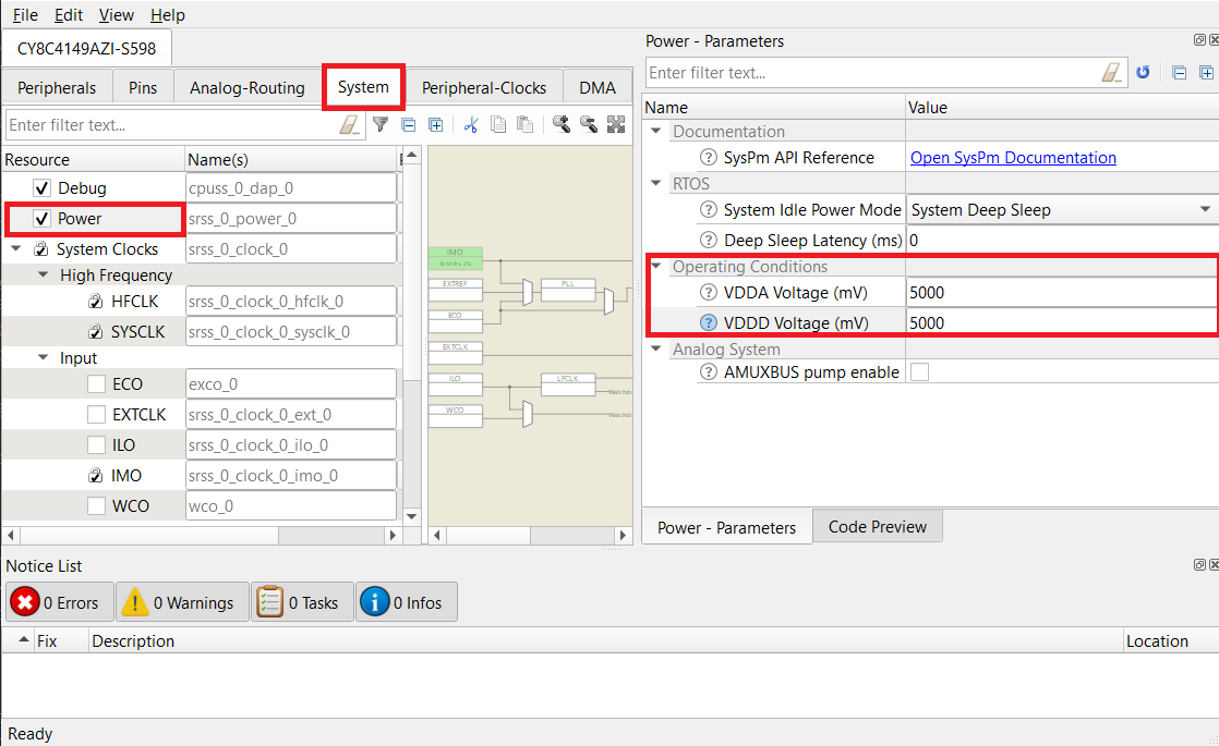

Note: PSoC™ 4100S Max Pioneer Kit has two onboard regulators 3.3 V and 5 V. To use 5 V, place the jumper J10 at positions 1 and 2. To use 3.3 V, place the jumper J10 at positions 2 and 3 and change the VDDA and VDDD voltage in the Device configurator - Systems tab to 3300 mV, see Figure 21. See the kit user guide for more details.
Resources and settings
See the Operation section for step-by-step instructions to configure the CAPSENSE™ Configurator.
Figure 22. Device configurator - EZI2C Peripheral parameters

The following ModusToolbox™ software resources are used in this example:
Table 5. Application resources
| Resource | Alias/object | Purpose |
|---|---|---|
| SCB (I2C) (PDL) | CYBSP_EZI2C | EZI2C slave driver to communicate with CAPSENSE™ tuner GUI |
| CAPSENSE™ | CYBSP_MSC0 | CAPSENSE™ driver to interact with the MSC hardware and interface the CAPSENSE™ sensors |
| Digital pin | CYBSP_USER_LED | To visualize the slider response |
Firmware flow
Figure 23. Firmware flowchart

Related resources
| Resources | Links |
|---|---|
| Application notes | AN79953 – Getting started with PSoC™ 4 AN85951 – PSoC™ 4 and PSoC™ 6 MCU CAPSENSE™ design guide |
| Code examples | Using ModusToolbox™ software on GitHub Using PSoC™ Creator |
| Device documentation | PSoC™ 4 datasheets PSoC™ 4 technical reference manuals |
| Development kits | Select your kits from the evaluation board finder |
| Libraries on GitHub | mtb-pdl-cat2 – PSoC™ 4 Peripheral Driver Library (PDL) mtb-hal-cat2 – Hardware Abstraction Layer (HAL) library |
| Middleware on GitHub | capsense – CAPSENSE™ library and documents |
| Tools | ModusToolbox™ software – ModusToolbox™ software is a collection of easy-to-use software and tools enabling rapid development with Infineon MCUs, covering applications from embedded sense and control to wireless and cloud-connected systems using AIROC™ Wi-Fi and Bluetooth® connectivity devices. PSoC™ Creator – IDE for PSoC™ and FM0+ MCU development |
Other resources
Infineon provides a wealth of data at www.infineon.com to help you select the right device, and quickly and effectively integrate it into your design.
Document history
Document title: CE232776 - PSoC™ 4: MSC self-capacitance slider tuning
| Version | Description of change |
|---|---|
| 1.0.0 | New code example |
| 2.0.0 | Major update to support ModusToolbox™ software v3.1 and CAPSENSE™ middleware v4.X |
© Cypress Semiconductor Corporation, 2020-2023. This document is the property of Cypress Semiconductor Corporation, an Infineon Technologies company, and its affiliates ("Cypress"). This document, including any software or firmware included or referenced in this document ("Software"), is owned by Cypress under the intellectual property laws and treaties of the United States and other countries worldwide. Cypress reserves all rights under such laws and treaties and does not, except as specifically stated in this paragraph, grant any license under its patents, copyrights, trademarks, or other intellectual property rights. If the Software is not accompanied by a license agreement and you do not otherwise have a written agreement with Cypress governing the use of the Software, then Cypress hereby grants you a personal, non-exclusive, nontransferable license (without the right to sublicense) (1) under its copyright rights in the Software (a) for Software provided in source code form, to modify and reproduce the Software solely for use with Cypress hardware products, only internally within your organization, and (b) to distribute the Software in binary code form externally to end users (either directly or indirectly through resellers and distributors), solely for use on Cypress hardware product units, and (2) under those claims of Cypress’s patents that are infringed by the Software (as provided by Cypress, unmodified) to make, use, distribute, and import the Software solely for use with Cypress hardware products. Any other use, reproduction, modification, translation, or compilation of the Software is prohibited.
TO THE EXTENT PERMITTED BY APPLICABLE LAW, CYPRESS MAKES NO WARRANTY OF ANY KIND, EXPRESS OR IMPLIED, WITH REGARD TO THIS DOCUMENT OR ANY SOFTWARE OR ACCOMPANYING HARDWARE, INCLUDING, BUT NOT LIMITED TO, THE IMPLIED WARRANTIES OF MERCHANTABILITY AND FITNESS FOR A PARTICULAR PURPOSE. No computing device can be absolutely secure. Therefore, despite security measures implemented in Cypress hardware or software products, Cypress shall have no liability arising out of any security breach, such as unauthorized access to or use of a Cypress product. CYPRESS DOES NOT REPRESENT, WARRANT, OR GUARANTEE THAT CYPRESS PRODUCTS, OR SYSTEMS CREATED USING CYPRESS PRODUCTS, WILL BE FREE FROM CORRUPTION, ATTACK, VIRUSES, INTERFERENCE, HACKING, DATA LOSS OR THEFT, OR OTHER SECURITY INTRUSION (collectively, "Security Breach"). Cypress disclaims any liability relating to any Security Breach, and you shall and hereby do release Cypress from any claim, damage, or other liability arising from any Security Breach. In addition, the products described in these materials may contain design defects or errors known as errata which may cause the product to deviate from published specifications. To the extent permitted by applicable law, Cypress reserves the right to make changes to this document without further notice. Cypress does not assume any liability arising out of the application or use of any product or circuit described in this document. Any information provided in this document, including any sample design information or programming code, is provided only for reference purposes. It is the responsibility of the user of this document to properly design, program, and test the functionality and safety of any application made of this information and any resulting product. "High-Risk Device" means any device or system whose failure could cause personal injury, death, or property damage. Examples of High-Risk Devices are weapons, nuclear installations, surgical implants, and other medical devices. "Critical Component" means any component of a High-Risk Device whose failure to perform can be reasonably expected to cause, directly or indirectly, the failure of the High-Risk Device, or to affect its safety or effectiveness. Cypress is not liable, in whole or in part, and you shall and hereby do release Cypress from any claim, damage, or other liability arising from any use of a Cypress product as a Critical Component in a High-Risk Device. You shall indemnify and hold Cypress, including its affiliates, and its directors, officers, employees, agents, distributors, and assigns harmless from and against all claims, costs, damages, and expenses, arising out of any claim, including claims for product liability, personal injury or death, or property damage arising from any use of a Cypress product as a Critical Component in a High-Risk Device. Cypress products are not intended or authorized for use as a Critical Component in any High-Risk Device except to the limited extent that (i) Cypress’s published data sheet for the product explicitly states Cypress has qualified the product for use in a specific High-Risk Device, or (ii) Cypress has given you advance written authorization to use the product as a Critical Component in the specific High-Risk Device and you have signed a separate indemnification agreement.
Cypress, the Cypress logo, and combinations thereof, WICED, ModusToolbox, PSoC, CapSense, EZ-USB, F-RAM, and Traveo are trademarks or registered trademarks of Cypress or a subsidiary of Cypress in the United States or in other countries. For a more complete list of Cypress trademarks, visit www.infineon.com. Other names and brands may be claimed as property of their respective owners.