esp_wifi_repeater
A full functional WiFi repeater (correctly: a WiFi NAT router)
This is an implementation of a WiFi NAT router on the esp8266 and esp8285. It also includes a basic firewall with ACLs, port mapping, traffic shaping, hooks for remote monitoring (or packet sniffing), MQTT management interface, and power management. For a setup with multiple routers in a mesh to cover a larger area a new mode "Automesh" has been included https://github.com/martin-ger/esp_wifi_repeater#automesh-mode .
Typical usage scenarios include:
- Simple range extender for an existing WiFi network
- Setting up an additional WiFi network with different SSID/password for guests or IoT devices
- Battery powered outdoor (mesh) networks
- Monitor probe for WiFi traffic analysis
The ESP acts as STA and as soft-AP and transparently forwards any IP traffic through it. As it uses NAT no routing entries are required neither on the network side nor on the connected stations. Stations are configured via DHCP by default in the 192.168.4.0/24 net and receive their DNS responder address from the existing WiFi network.
Measurements show, that it can achieve about 5 Mbps in both directions, so even streaming is possible.
Some details are explained in this video: https://www.youtube.com/watch?v=OM2FqnMFCLw
Note on WPA2 enterprise (PEAP)
If you need a "converter" that translates a WPA2 enterprise network with PEAP authentication into a WPA2-PSK network, have a look at https://github.com/martin-ger/esp_peap_psk . Was trying to integrate this functionality into this project - however this is difficult, as WPA2 enterprise requires so much free heap during authentication that there is hardly any mem left for anything else. So I decided to leave that in a separate project.
Note on WPA2 KRACK security issue
The lastest firmware (after 17/Oct/2017) has been build with the patched version of the SDK 2.1.0 from Espressif that mitigates the KRACK (https://www.krackattacks.com/ ) attack.
First Boot
The esp_wifi_repeater starts with the following default configuration:
- ap_ssid: MyAP, ap_password: none, ap_on: 1, ap_open: 1
- network: 192.168.4.0/24
After first boot (or factory reset) it will offer a WiFi network with an open AP and the ssid "MyAP". It does not yet try to automatically re-connect to an uplink AP (as it does not know a valid ssid or password).
Connect to this WiFi network and do the basic configuration either via a simple web interface or the full config with all options via the console.
Basic Web Config Interface
The web interface allows for the configuration of all parameters required for the basic forwarding functionality. Thanks to rubfi for the major work on that: https://github.com/rubfi/esp_wifi_repeater/ . Point your browser to "http://192.168.4.1". This page should appear:
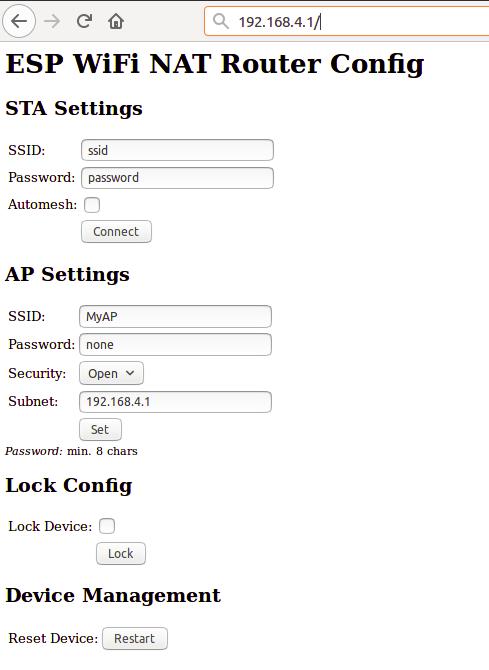
First enter the appropriate values for the uplink WiFi network, the "STA Settings", and click "Connect". Use password "none" for open networks. The ESP reboots and will connect to your WiFi router. The status LED should be blinking after some seconds.
Now you can reload the page and change the "Soft AP Settings". Click "Set" and again the ESP reboots. Now it is ready for forwarding traffic over the newly configured Soft AP. Be aware that these changes also affect the config interface, i.e. to do further configuration, connect to the ESP through one of the newly configured WiFi networks. For access through the Soft AP remember the address of the Soft APs network if you have changed that (the ESP has always the address x.x.x.1 in this network).
If you like, you can mark the "lock" checkbox and click "Lock". Now the config cannot be changed anymore without first unlocking it with the uplink WiFi network's password (define one even if the network is open).
If you did a mistake and you lost any contact with ESP you can still use the serial console to recover it ("reset facory", see below).
Command Line Interface
Advanced configuration has to be done via the command line on the console interface. This console is available either via the serial port at 115200 baud or via tcp port 7777 (e.g. "telnet 192.168.4.1 7777" from a connected STA).
Use the following commands for an initial setup:
- set ssid your_home_router's_SSID
- set password your_home_router's_password
- set ap_ssid ESP's_ssid
- set ap_password ESP's_password
- show (to check the parameters)
- save
- reset
If you want to enter non-ASCII or special characters on the command line you can use quoting: either use C-style quotes with backslash like this "My\ AccessPoint" or use HTTP-style hex encoding like "My%20AccessPoint". Both methods will result in a string "My AccessPoint". With the hex encoding you can enter any byte value you like, except for 0 (for C-internal reasons).
The command line understands a lot more commands:
Basic commands
Enough to get it working in nearly all environments.
- help: prints a short help message
- set [ssid|password] value: changes the settings for the uplink AP (WiFi config of your home-router), use password "none" for open networks.
- set [ap_ssid|ap_password] value: changes the settings for the soft-AP of the ESP (for your stations)
- show [config|stats]: prints the current config or some status information and statistics
- save [dhcp]: saves the current config parameters [+ the current DHCP leases] to flash
- lock [password]: saves and locks the current config, changes are not allowed. Password can be left open if already set before (Default is the password of the uplink WiFi)
- unlock password: unlocks the config, requires password from the lock command
- reset [factory]: resets the esp, 'factory' optionally resets WiFi params to default values (works on a locked device only from serial console)
- quit: terminates a remote session
Advanced commands
Most of the set-commands are effective only after save and reset.
Automesh config
- set automesh [0|1]: selects, whether the automesh mode is on or off (default), see details here https://github.com/martin-ger/esp_wifi_repeater#automesh-mode
- set am_scan_time secs: sets the time interval in seconds the ESP tries in automesh mode to find an uplink AP before going to sleep (0 disabled, default)
- set am_sleep_time secs: sets the time interval in seconds the ESP sleeps in automesh mode if no uplink AP is found (0 disabled, default)
WiFi config
- set ap_on [0|1]: selects, whether the soft-AP is disabled (ap_on=0) or enabled (ap_on=1, default)
- set ap_open [0|1]: selects, whether the soft-AP uses WPA2 security (ap_open=0, automatic, if an ap_password is set) or open (ap_open=1)
- set auto_connect [0|1]: selects, whether the STA should keep retrying to reconnect to the AP. auto_connect is off (0) after first flashing or after "reset factory". When you enter a new SSID it will be automatically set on (1).
- set ssid_hidden [0|1]: selects, whether the SSID of the soft-AP is hidden (ssid_hidden=1) or visible (ssid_hidden=0, default)
- set phy_mode [1|2|3]: sets the PHY_MODE of the WiFi (1=b, 2=g, 3=n(default))
- set bssid xx:xx:xx:xx:xx:xx: sets the specific BSSID of the uplink IP to connect to (default 00:00:00:00:00:00 which means any)
- set [ap_mac|sta_mac] xx:xx:xx:xx:xx:xx: sets the MAC address of the STA and SOFTAP to a user defined value (bit 0 of the first byte of the MAC address can not be 1) scan: does a scan for APs
TCP/IP config
- ping ip-addr: checks IP connectivity with ICMP echo request/reply
- set network ip-addr: sets the IP address of the internal network, network is always /24, router is always x.x.x.1
- set dns dns-addr: sets a static DNS address that is distributed to clients via DHCP
- set dns dhcp: configures use of the dynamic DNS address from DHCP, default
- set ip ip-addr: sets a static IP address for the ESP in the uplink network
- set ip dhcp: configures dynamic IP address for the ESP in the uplink network, default
- set netmask netmask: sets a static netmask for the uplink network
- set gw gw-addr: sets a static gateway address in the uplink network
- portmap add [TCP|UDP] external_port internal_ip internal_port: adds a port forwarding
- portmap remove [TCP|UDP] external_port: deletes a port forwarding
Firewall/Monitor config
- acl [from_sta|to_sta] [TCP|UDP|IP] src-ip [src_port] desr-ip [dest_port] [allow|deny|allow_monitor|deny_monitor]: adds a new rule to the ACL
- acl [from_sta|to_sta] clear: clears the whole ACL
- show acl: shows the defined ACLs and some stats
- set acl_debug [0|1]: switches ACL debug output on/off - a denied packets will be logged to the terminal
- set [upstream_kbps|downstream_kbps] bitrate: sets a maximum upstream/downstream bitrate (0 = no limit)
- monitor [on|off|acl] port: starts and stops monitor server on a given port
Interface config
- set config_port portno: sets the port number of the console login (default is 7777, 0 disables remote console config)
- set web_port portno: sets the port number of the web config server (default is 80, 0 disables web config)
- set config_access mode: controls the networks that allow config access for console and web (0: no access, 1: only internal, 2: only external, 3: both (default))
Chip config
- set speed [80|160]: sets the CPU clock frequency (default 80 Mhz)
- sleep seconds: Put ESP into deep sleep for the specified amount of seconds. Valid values between 1 and 4294 (aprox. 71 minutes)
- set status_led GPIOno: selects a GPIO pin for the status LED (default 2, >16 disabled)
- set vmin voltage: sets the minimum battery voltage in mV. If Vdd drops below, the ESP goes into deep sleep. If 0, nothing happens
- set vmin_sleep secs: sets the time interval in seconds the ESP sleeps on low voltage
Status LED
In default config GPIO2 is configured to drive a status LED (connected to GND) with the following indications:
- permanently on: started, but not successfully connected to the AP (no valid external IP)
- flashing (1 per second): working, connected to the AP
- unperiodically flashing: working, traffic in the internal network
With "set status_led GPIOno" the GPIO pin can be changed (any value > 16, e.g. "set status_led 255" will disable the status LED completely). When configured to GPIO1, it works with the buildin blue LED on the ESP-01 boards. However, as GPIO1 ist also the UART-TX-pin this means, that the serial console is not working. Configuration is then limited to network access.
Port Mapping
In order to allow clients from the external network to connect to server port on the internal network, ports have to be mapped. An external port is mapped to an internal port of a specific internal IP address. Use the "portmap add" command for that. Port mappings can be listed with the "show" command and are saved with the current config.
However, to make sure that the expected device is listening at a certain IP address, it has to be ensured the this devices has the same IP address once it or the ESP is rebooted. To achieve this, either fixed IP addresses can be configured in the devices or the ESP has to remember its DHCP leases. This can be achieved with the "save dhcp" command. It saves the current state and all DHCP leases, so that they will be restored after reboot. DHCP leases can be listed with the "show stats" command.
Automesh Mode
Sometimes you might want to use several esp_wifi_repeaters in a row or a mesh to cover a larger distance or area. Generally, this can be done without any problems with NAT routers, actually you will have several layers of NAT. However, this means connectivity is limited: all nodes can talk to the internet, but generally there's no direct IP connectivity between the nodes. And, of course, the available bandwidth goes down the more hops you need. But users have reported that even 5 esp_wifi_repeaters in a row work quite well.
In such a setup configuration is quite a time consuming and error-prone activity. To simplify that, the esp_wifi_repeater now has a new mode: "Automesh". Just configure the SSID and the password and switch "automesh" on. (either on the CLI with "set automesh 1" or on the Web interface with just select the checkbox). This will do the following:
Each esp_wifi_repeater configured in that way will automatically offer a WiFi network on the AP with the same SSID/password as it is connected to. Clients can use the same WiFi settings for the original network or the repeated ones. Each esp_wifi_repeater configured with "automesh" will first search for the best other AP to connect to. This is the one which is closest to the original WiFi network and has the best signal strength (RSSI).
The signal strength is easy to measure with a scan, but which is the one closest to the original WiFi network when you see several APs with the same SSID? Therefore the protocol use a somewhat dirty trick: the esp_wifi_repeaters in "automesh" mode manipulate their BSSID, i.e. the MAC address of their AP interface, which is send out with every beacon frame 10 about time times per second. It uses the format: 24:24:mm:rr:rr:rr. "24:24" is just the unique identifier of a repeater (there is a minimal probability that this collides with the real APs MAC, but we can neglect this, as we can change that prefix if really required). "mm" means the "mesh level", this is the distance in hops to the original WiFi network. The last three "rr:rr:rr" are just random numbers to distinguish the various ESPs. The original AP keeps its BSSID, i.e. the one without the prefix "24:24" is recognized as root, called mesh level 0.
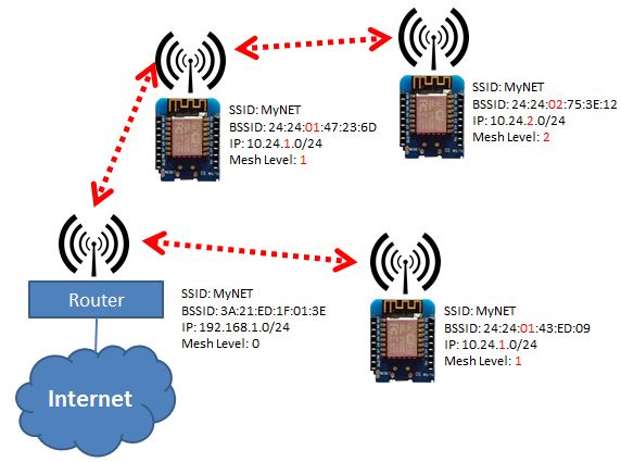
Now each esp_wifi_repeater can learn which other esp_wifi_repeater is the closest to the the original WiFi network, can connect to that, and chose its own BSSID accordingly. Also the IP address of the internal network is adjusted to the mesh level: 10.24.m.0. This creates a tree (a very special mesh) with the original WiFi AP as root and repeating nodes on several mesh levels (actually, it works somewhat similar as the Spanning Tree Protocol (STP) on the link layer or routing on the network layer using a Distance Vector protocol). As soon as an uplink link loss is detected, configuration is restarted. This should avoid loops, as during (re-)configuration also no beacons with an BSSID are sent.
For convenience, the esp_wifi_repeater after "automesh" configuration first tries to check, whether it can connect to an uplink AP. If this fails, even when an AP with the correct SSID has been found, it assumes, the user did a mistake with the password and resets to factory defaults. After it had connected successfully once, it will assume config is correct and keep on trying after connection loss or reset as long as it takes (to avoid a DOS attack with a misconfigured AP).
Using the two parameters am_scan_time and am_sleep_time power management can be implemented in automesh mode, if you have connected GPIO16 to RST. After booting the esp_wifi_repeater scans for avilable uplink APs for am_scan_time seconds. If none is found, it goes to deepsleep for am_sleep_time seconds and tries again after reboot (default is 0 = disabled for both parameters).
Monitoring
From the console a monitor service can be started ("monitor on [portno]"). This service mirrors the traffic of the internal network in pcap format to a TCP stream. E.g. with a "netcat [external_ip_of_the_repeater] [portno] | sudo wireshark -k -S -i -" from an computer in the external network you can now observe the traffic in the internal network in real time. Use this e.g. to observe with which internet sites your internals clients are communicating. Be aware that this at least doubles the load on the esp and the WiFi network. Under heavy load this might result in some packets beeing cut short or even dropped in the monitor session. CAUTION: leaving this port open is a potential security issue. Anybody from the local networks can connect and observe your traffic.
Firewall
The ESP router has a integrated basic firewall. ACLs (Access Control Lists) can be applied to the SoftAP interface. This is a cornerstone in IoT security, when the router is used to bring other IoT devices into the internet. It can be used to prevent e.g. third-party IoT devices from "calling home", being misused as malware bots, and to protect your home network with PCs, tablets and phones from being visible to home automation devices.
The two ACL lists are named "from_sta" and "to_sta" for incoming and outgoing packets. ACLs are defined in "CISCO IOS style". The following example will allow for outgoing local broadcasts (for DHCP), UDP 53 (DNS), and TCP 1883 (MQTT) to a local broker, any other packets will be blocked:
- acl from_sta clear
- acl from_sta IP any 255.255.255.255 allow
- acl from_sta UDP any any any 53 allow
- acl from_sta TCP any any 192.168.0.0/16 1883 allow
- acl from_sta IP any any deny
ACLs for the "to_sta" direction may be defined as well, but this is usually not required, as the reverse direction is quite well protected against unsolicited traffic by the NAT transation.
ACLs consist of filtering rules that are processed for each packet. Each rule consists of a protocol (IP, TCP, or UDP), source address/port, destination address/port, as well as an action "allow" or "deny". In case of plain IP no ports, only addresses are given. IP rules include TCP and UDP packets. Addresses can be given as subnet addresses in the "/" notation, e.g. 192.168.178.0/24. Also "any" can be used as wildcard, it matches on any address or portnumber. A rule is defined by the "acl" command:
- acl [from_sta|to_sta] [TCP|UDP|IP] src-ip [src_port] desr-ip [dest_port] [allow|deny|allow_monitor|deny_monitor]
The rules are processed top-down in the order of their appearance in the list. The first rule that matches a packet is applied and determies whether a packet is allowed (and forwarded) or denied (and dropped). This means, special cases first, general rules at the end. If there are rules in an ACL all packets that don't match any rule are denied by default. Thus, the last rule "from_sta IP any any deny" in the example above is not really needed, as it is the default anyway. If an ACL is empty, all packets are allowed.
Definition of ACL rules works also top-down: a new rule is always added at the end of a list. To change an ACL you first have to clear it completely (acl from_sta clear) and then rebuild it. ACLs are saved with the config. "show acl" will print out the ACLs plus statistics on the number of hits for each rule and the overall number of allowed and denied packets.
With the command "set acl_debug 1" a summary of all denied packets is printed to the console. Also, an MQTT topic can publishe this summary. This can be used for firewall configuration to determine which rules are required to get the connected devices working. It also gives a hint if, if unexpected traffic happens (and is denied).
For deeper analysis the monitoring service can be used (even denied packets are reported to the monitor before they are dropped). When the monitor is started with the "monitor acl port" command, ACLs can be used as online filters. All rules that are defined as "allow_monitor" instead of "allow" and "deny_monitor" instead of "deny" are processed as usual, resulting in allowing of forwarding a packet, but they also send the packet to the monitor. Thus a list of rules that basically "allow" or "allow_monitor" all packets still makes sense, as it can be used to select already during catpure time which packet should be recorded. E.g. a lists:
-
acl from_sta clear
-
acl from_sta IP 192.168.0.0/16 any allow_monitor
-
acl from_sta IP any any allow
-
acl to_sta clear
-
acl to_sta IP any 192.168.0.0/16 allow_monitor
-
acl to_sta IP any any allow
will allow all packets and also select all packets for monitoring that go from a station to the 192.168.0.0/16 (local)subnet and from the 192.168.0.0/16 to a station. Of course such a filter can be applied also after the capture to a full monitoring trace, but if you already know, what you are looking for, these online filters will help to reduce monitoring overhead drastically. It can also be used to debug all deny firewall rules by simply using "deny_monitor" instead of deny.
Bitrate Limits
By setting upstream_kbps and downstream_kbps to a value != 0 (0 is the default), you can limit the maximum bitrate of the ESP's AP. This value is a limit that applies to the traffic of all connected clients. Packets that would exeed the defined bitrate are dropped. The traffic shaper uses the "Token Bucket" algorithm with a bucket size of currently four times the bitrate per seconds, allowing for bursts, when there was no traffic before.
MQTT Support
Since version 1.3 the router has a build-in MQTT client (thanks to Tuan PM for his library https://github.com/tuanpmt/esp_mqtt). This can help to integrate the router/repeater into the IoT. A home automation system can e.g. make decisions based on infos about the currently associated stations, it can switch on and of the repeaters (e.g. based on a time schedule), or it can simply be used to monitor the load. The router can be connected either to a local MQTT broker or to a publicly available broker in the cloud. However, currently it does not support TLS encryption.
By default the MQTT client is disabled. It can be enabled by setting the config parameter "mqtt_host" to a hostname different from "none". To configure MQTT you can set the following parameters:
- set mqtt_host IP_or_hostname: IP or hostname of the MQTT broker ("none" disables the MQTT client)
- set mqtt_port port: Port of the MQTT broker used for connection (default: 1883)
- set mqtt_user username: Username for authentication ("none" if no authentication is required at the broker)
- set mqtt_user password: Password for authentication
- set mqtt_id clientId: Id of the client at the broker (default: "ESPRouter_xxxxxx" derived from the MAC address)
- set mqtt_prefix prefix_path: Prefix for all published topics (default: "/WiFi/ESPRouter_xxxxxx/system", again derived from the MAC address)
- set mqtt_command_topic command_topic: Topic subscribed to receive commands, same as from the console. (default: "/WiFi/ESPRouter_xxxxxx/command", "none" disables commands via MQTT)
- set mqtt_interval secs: Set the interval in which the router publishs status topics (default: 15s, 0 disables status publication)
- set mqtt_mask mask_in_hex: Selects which topics are published (default: "ffff" means all)
The MQTT parameters can be displayed with the "show mqtt" command.
The router can publish the following status topics periodically (every mqtt_interval):
- prefix_path/Uptime: System uptime since last reset in s (mask: 0x0020)
- prefix_path/Vdd: Voltage of the power supply in mV (mask: 0x0040)
- prefix_path/Bpsin: Bytes/s from stations into the AP (mask: 0x0800)
- prefix_path/Bpsout: Bytes/s from the AP to stations (mask: 0x1000)
- prefix_path/Ppsin: Packets/s from stations into the AP (mask: 0x0200)
- prefix_path/Ppsout: Packets/s from the AP to stations (mask: 0x0400)
- prefix_path/Bin: Total bytes from stations into the AP (mask: 0x0100)
- prefix_path/Bout: Total bytes from the AP to stations (mask: 0x0100)
- prefix_path/NoStations: Number of stations currently connected to the AP (mask: 0x2000)
In addition it can publish on an event basis:
- prefix_path/join: MAC address of a station joining the AP (mask: 0x0008)
- prefix_path/leave: MAC address of a station leaving the AP (mask: 0x0010)
- prefix_path/IP: IP address of the router when received via DHCP (mask: 0x0002)
- prefix_path/ScanResult: Separate topic for the results of a "scan" command (one message per found AP) (mask: 0x0004)
- prefix_path/ACLDeny: A packet has been denied by an ACL rule and has been dropped (mask: 0x0080)
The router can be configured using the following topics:
- command_topic: The router subscribes on this topic and interprets all messages as command lines
- prefix_path/response: The router publishes on this topic the command line output (mask: 0x0001)
If you now want the router to publish e.g. only Vdd, its IP, and the command line output, set the mqtt_mask to 0x0001 | 0x0002 | 0x0040 (= "set mqtt_mask 0043").
Power Management
The repeater monitors its current supply voltage (shown in the "show stats" command). If vmin (in mV, default 0) is set to a value > 0 and the supply voltage drops below this value, it will go into deep sleep mode for vmin_sleep seconds. If you have connected GPIO16 to RST (which is hard to solder on an ESP-01) it will reboot after this interval, try to reconnect, and will continue its measurements. If vmin is saved with the config, it will sleep over and over again, until the supply voltage raises above the threshold. These settings are especially (only?) useful if you have powered the ESP with a (lithium) battery whithout undercharge protection. Then a value of 2900mV-3000mV is probably helpful, as it reduces power consumption of the ESP to a minimum and you have much more time to recharge or replace the battery before damage. This only makes sense, if you have the ESP connected directly to the battery. If you have additional logic, this will still drain the battery.
You can send the ESP to sleep manually once by using the "sleep" command.
Caution: If you save a vmin value higher than the max supply voltage to flash, the repeater will immediately shutdown every time after reboot. Then you have to wipe out the whole config by flashing blank.bin (or any other file) to 0x0c000.
Building and Flashing
To build this binary you download and install the esp-open-sdk (https://github.com/pfalcon/esp-open-sdk). Make sure, you can compile and download the included "blinky" example.
Then download this source tree in a separate directory and adjust the BUILD_AREA variable in the Makefile and any desired options in user/user_config.h. Build the esp_wifi_repeater firmware with "make". "make flash" flashes it onto an esp8266.
The source tree includes a binary version of the liblwip_open plus the required additional includes from my fork of esp-open-lwip. No additional install action is required for that. Only if you don't want to use the precompiled library, checkout the sources from https://github.com/martin-ger/esp-open-lwip . Use it to replace the directory "esp-open-lwip" in the esp-open-sdk tree. "make clean" in the esp_open_lwip dir and once again a "make" in the upper esp_open_sdk directory. This will compile a liblwip_open.a that contains the NAT-features. Replace liblwip_open_napt.a with that binary.
If you want to use the complete precompiled firmware binaries you can flash them with "esptool.py --port /dev/ttyUSB0 write_flash -fs 4MB -ff 80m -fm dio 0x00000 firmware/0x00000.bin 0x10000 firmware/0x10000.bin" (use -fs 1MB for an ESP-01). For the esp8285 you must use -fs 1MB and -fm dout.
On Windows you can flash it using the "ESP8266 Download Tool" available at https://espressif.com/en/support/download/other-tools. Download the two files 0x00000.bin and 0x10000.bin from the firmware directory. For a generic ESP12, a NodeMCU or a Wemos D1 use the following settings (for an ESP-01 change FLASH SIZE to "8Mbit"):
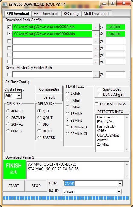
If "QIO" mode fails on your device, try "DIO" instead. Also have a look at the "Detected Info" to check size and mode of the flash chip.
Sometimes, especially on old ESP-01s, there is a wrong or non-matching version of "esp_init_data_default.bin" in the flash. If the firmware files from above flash correctly but after reboot you see only garbage on the serial and/or the LED on GPIO2 is flashing rapidly, try to re-initialize this sector: download https://github.com/espressif/ESP8266_NONOS_SDK/raw/master/bin/esp_init_data_default_v08.bin and flash it to 0x7c000 for 512 kB modules (some ESP-01, Sonoff Switch), 0xfc000 for 1 MB modules (most ESP-01), or 0x3fc000 for 4 MB modules (most ESP-12, Wemos D1).
If your downloaded firmware still doesn't start properly, please check with the enclosed checksums whether the binary files are possibly corrupted.
Known Issues
- Due to the limitations of the ESP's SoftAP implementation, there is a maximum of 8 simultaniously connected stations.
- Configuration via TCP (write_flash) requires a good power supply. Try to check this, if you ESP runs unstable. A large capacitor between Vdd and Gnd can help if you experience problems here.