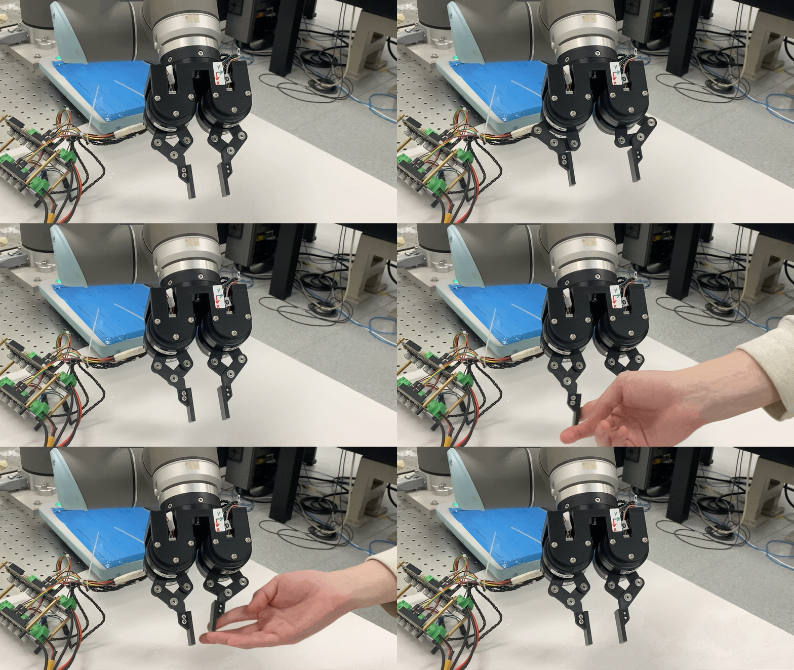
In this project, we have implemented a two-fingered 4-DoF direct-drive hand, inspired by the work "Direct Drive Hands: Force-Motion Transparency in Gripper Design".
- ODrive 3.6-56V ⨉2
- T-Motor GB54-2 ⨉4
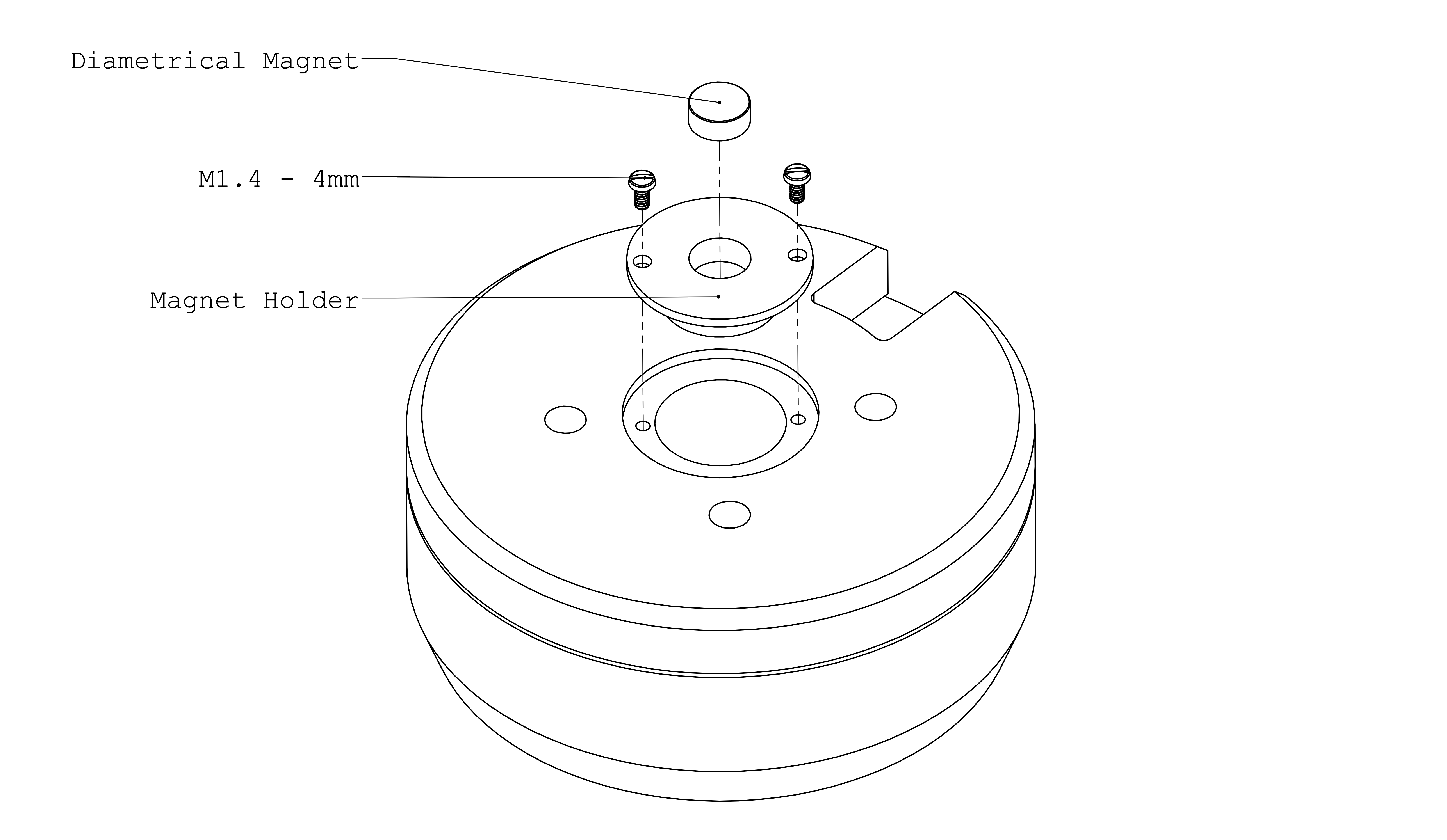
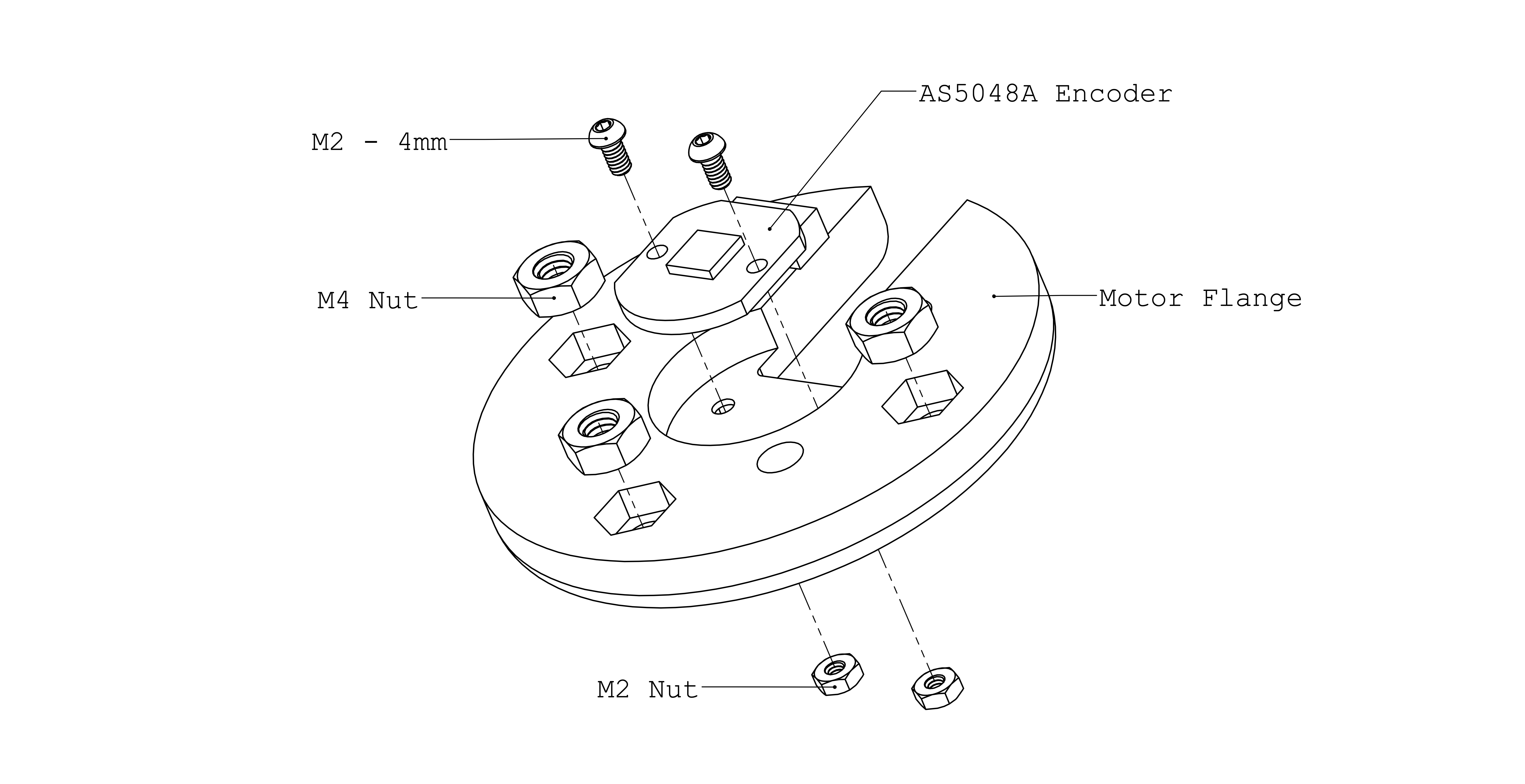
- AS5048A Encoder + Diametrical Magenet ⨉4
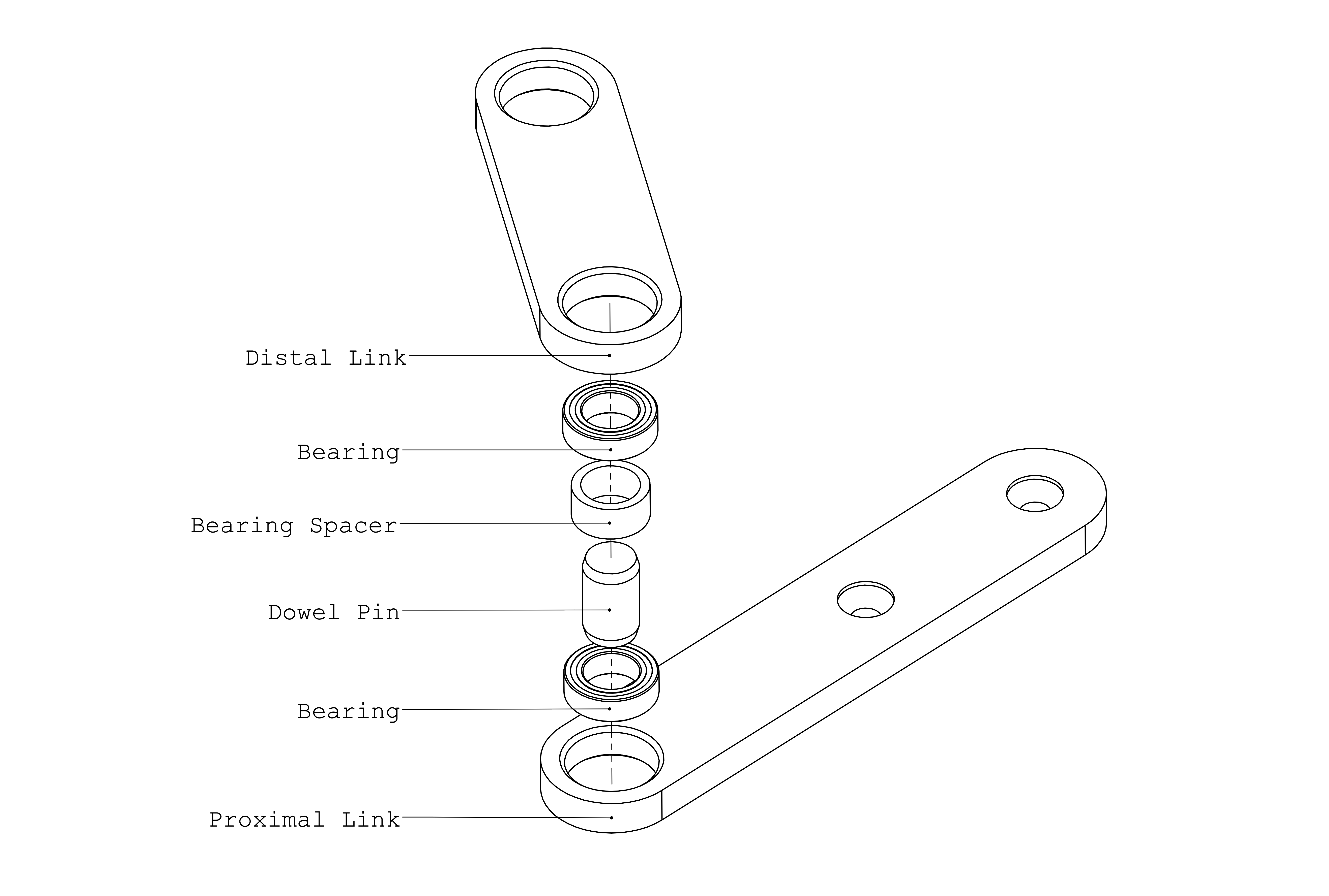
- Bearing - outer-diameter = 10mm, inner-diameter = 6mm ⨉12
- Dowel Pin - diameter = 6mm, length = 10mm ⨉6
- 14-Core Shielded Cable TRVVSP4 ⨉2 meters
- MX1.25-6P 150mm Cable ⨉4
- AMASS Braided 3-Phase 90cm Cable ⨉8
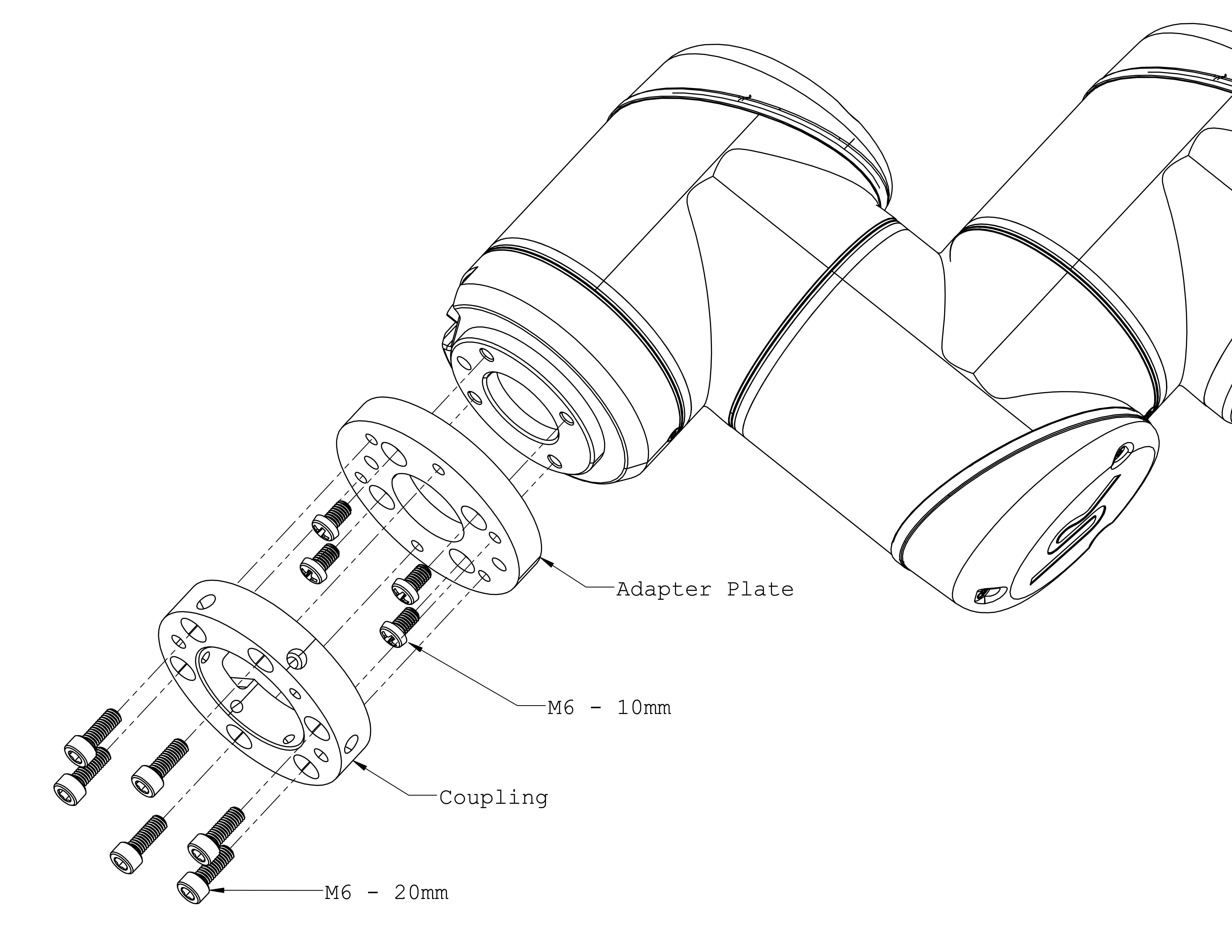
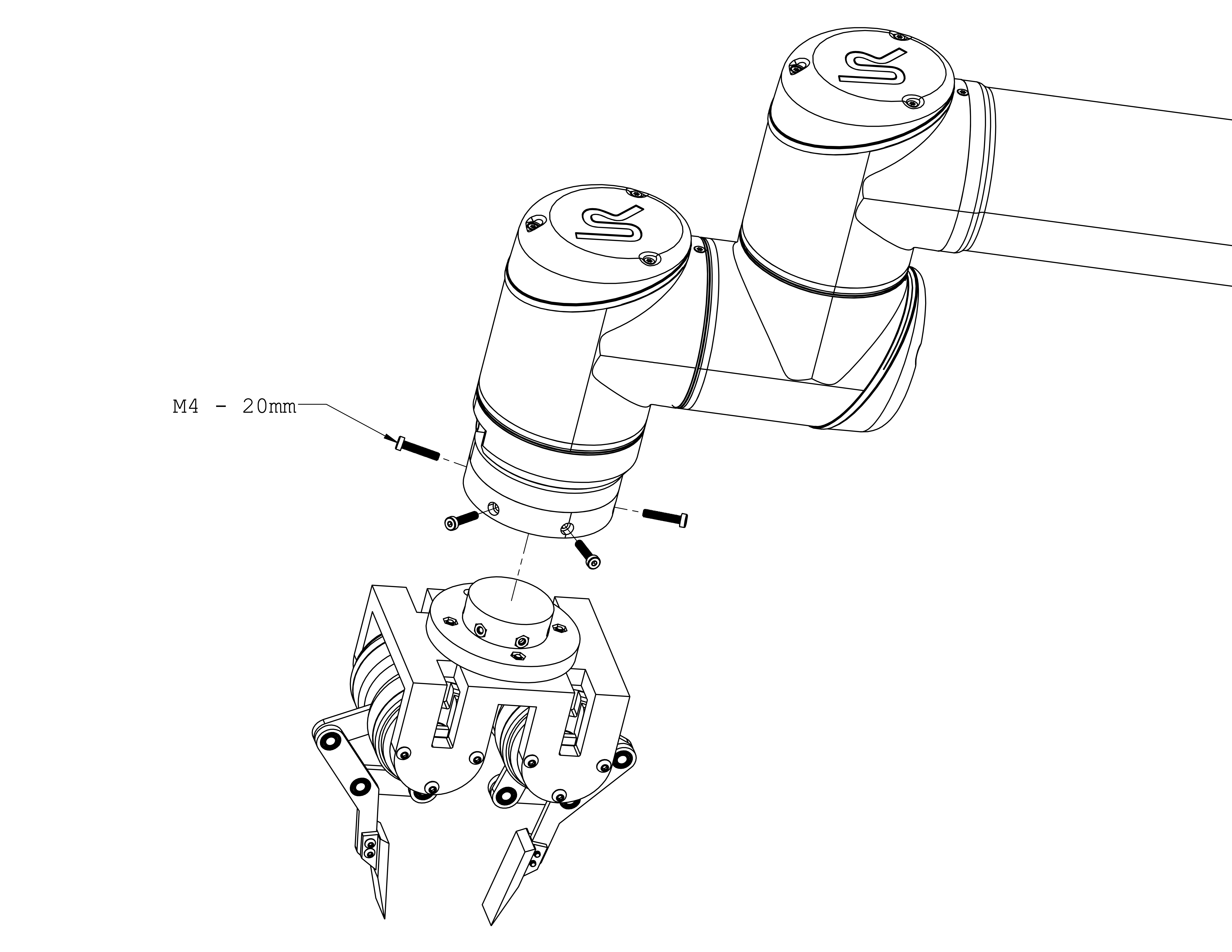
- Adapter Plate and Coupling: The gripper is primarily designed to be compatible with Universal Robots UR10 (50mm PCD with 4 ⨉ M6, used with Robotiq's grippers). For other robot systems, see the section Customization for instructions.
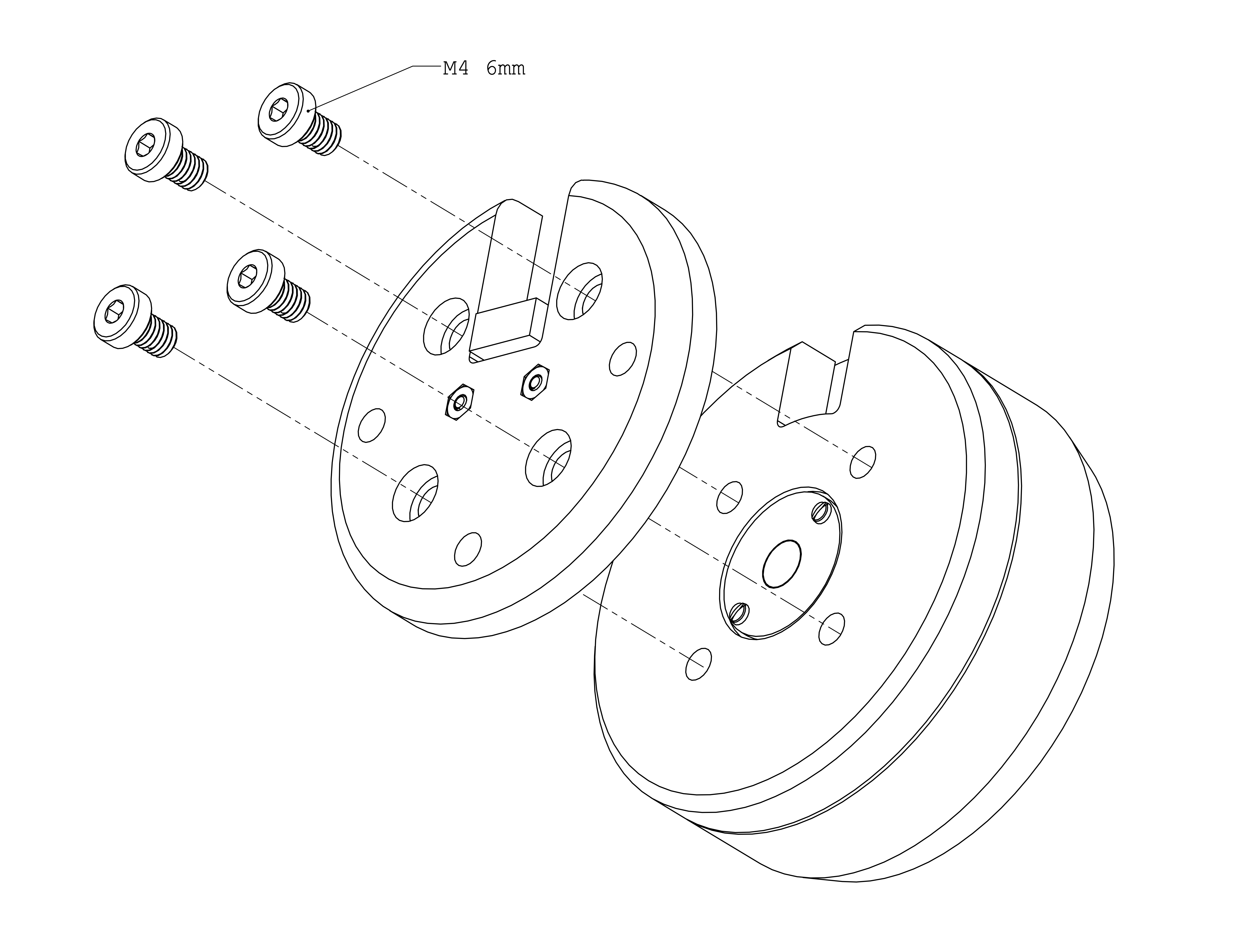
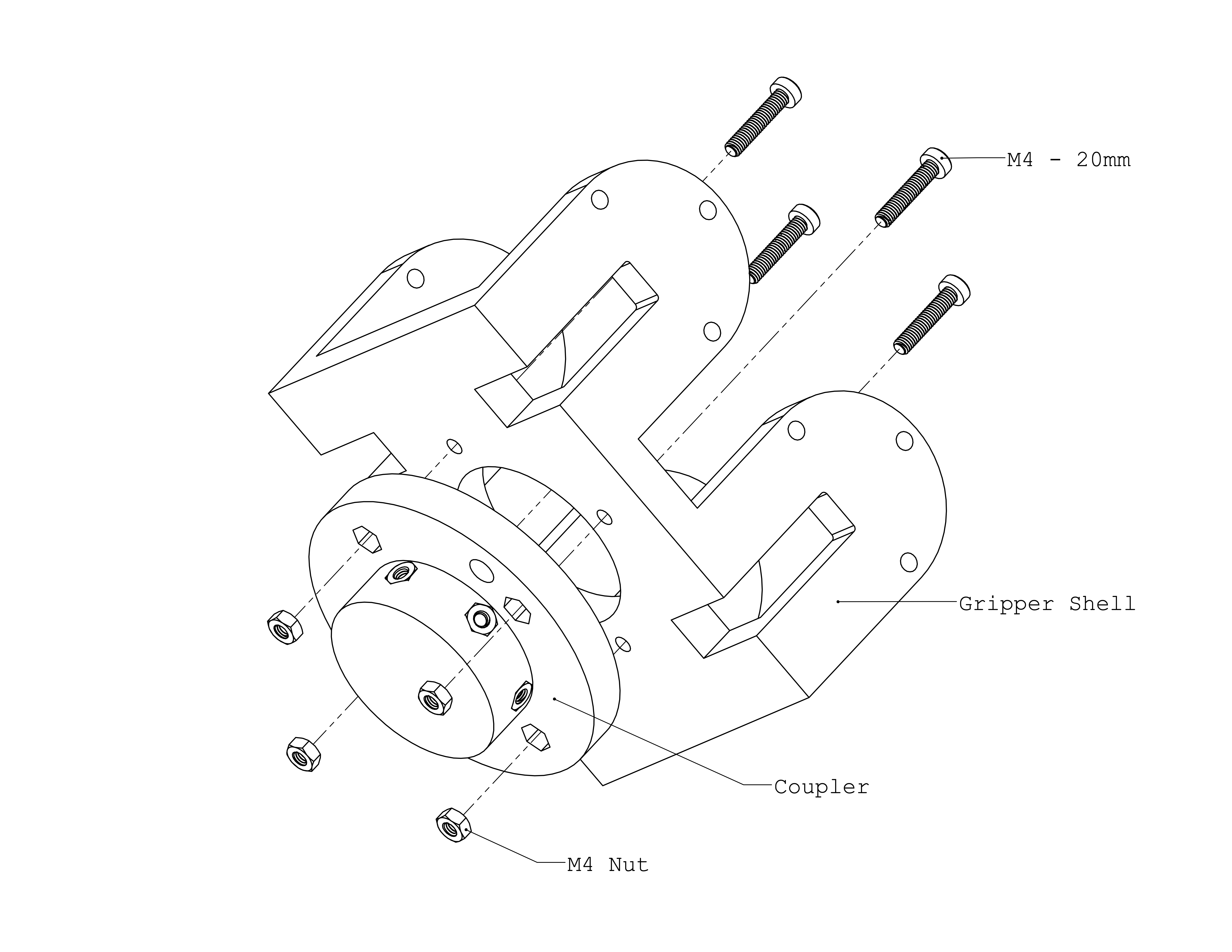
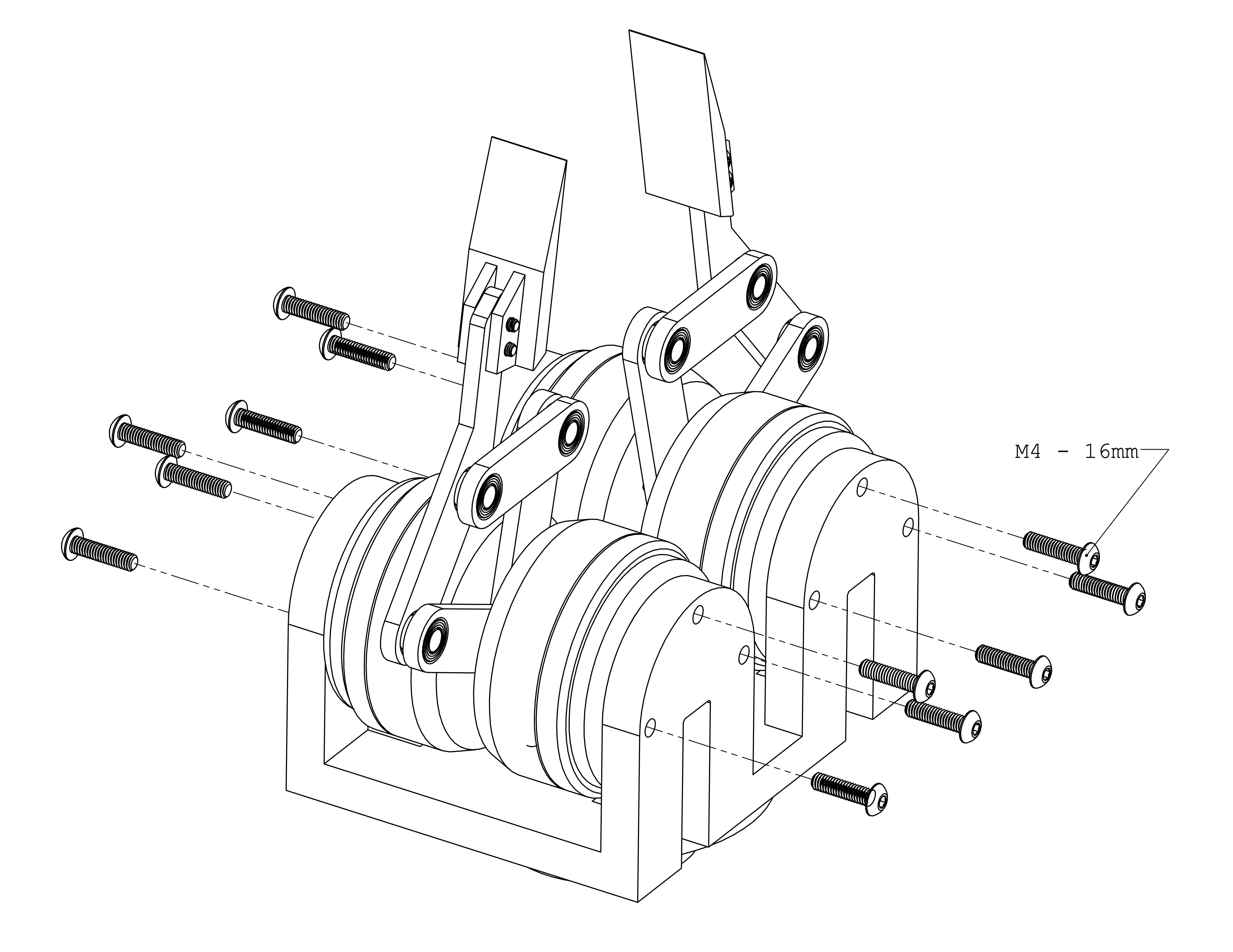
- Various Fasteners from M2 to M4
- Magnet Holder ⨉4
- Motor Plate ⨉4
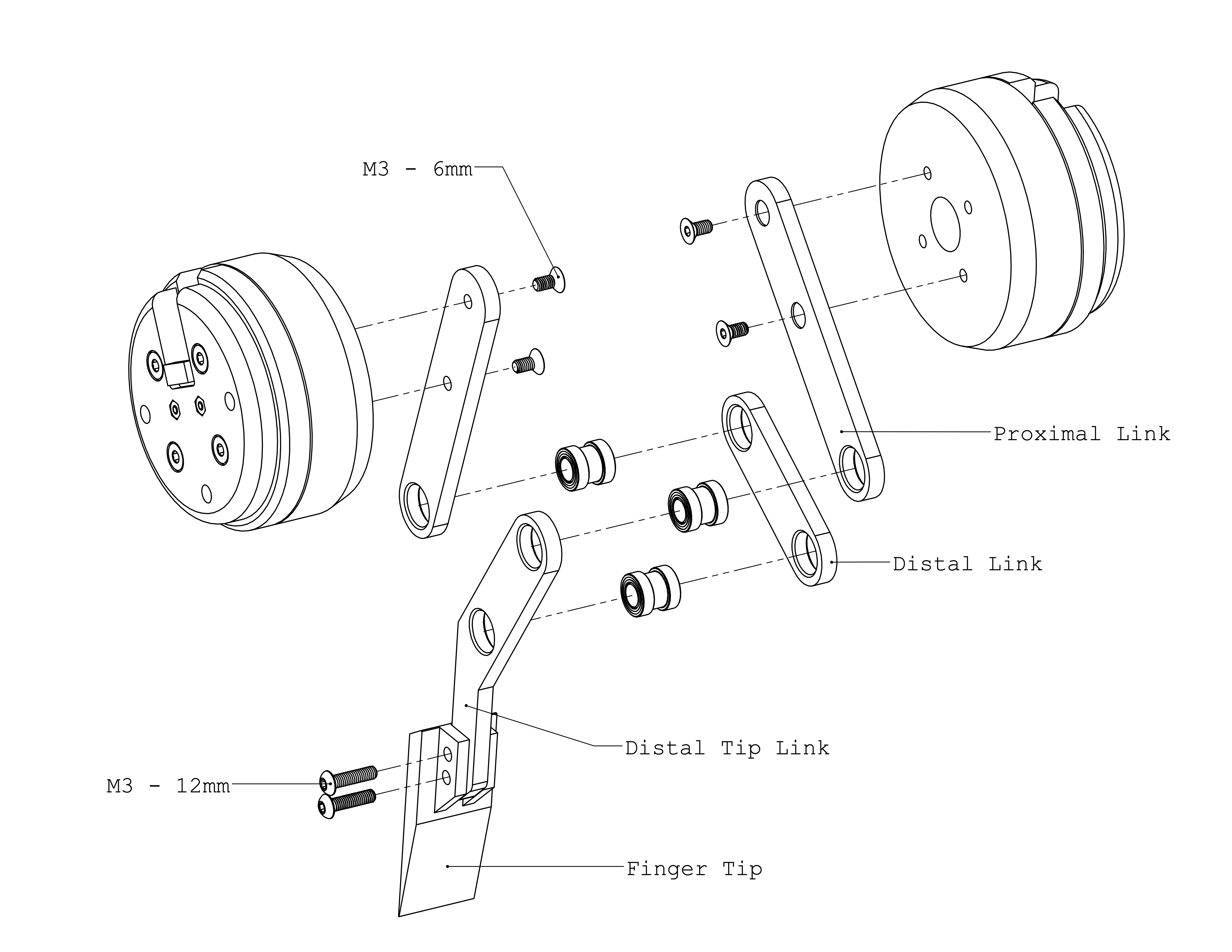
- Proximal Link ⨉4
- Distal Link ⨉2
- Distal Tip Link ⨉2
- Finger Tip ⨉2
- Gripper Shell ⨉1
- Coupler ⨉1
- Calibration Stand ⨉4
- Calibration Arm ⨉4
ddh_driver is our driver software that provides a user interface to the gripper hardware. To install, visit here.
Labeling parts can facilitate assembly.
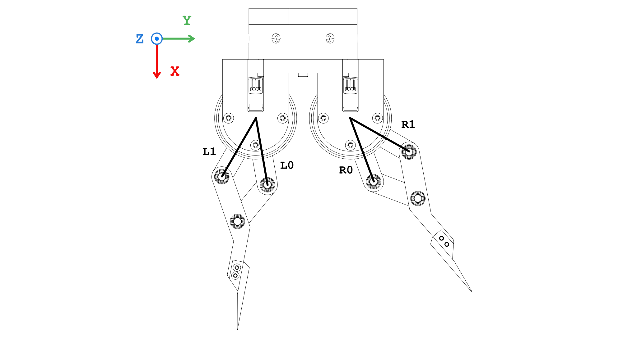
Label the four motors with R0, R1, L0, L1, respectively. The motors will not be interchangeable later.
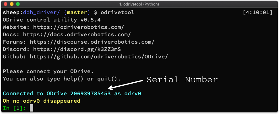
Label the two ODrive boards with ODrive_R and ODrive_L respectively. Record their serial numbers in ddh_driver/config/default.yaml. You can check the serial number using odrivetool in the terminal.
odrive_serial:
  R: 'Serial Number of ODrive_R'
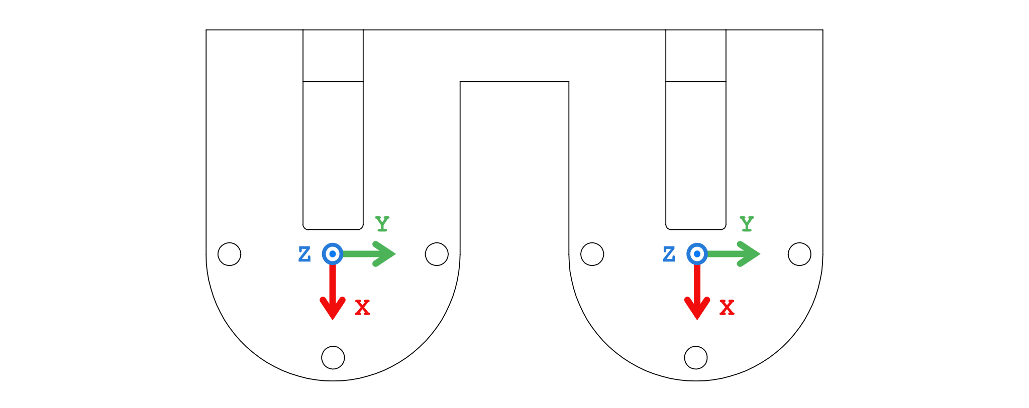
L: 'Serial Number of Odrive_L'On one side of the 3D-printed part Gripper Shell (to be used as the top side), mark reference frames as follows.
Actuator = BLDC Motor + Magnet + Encoder + Drive Board
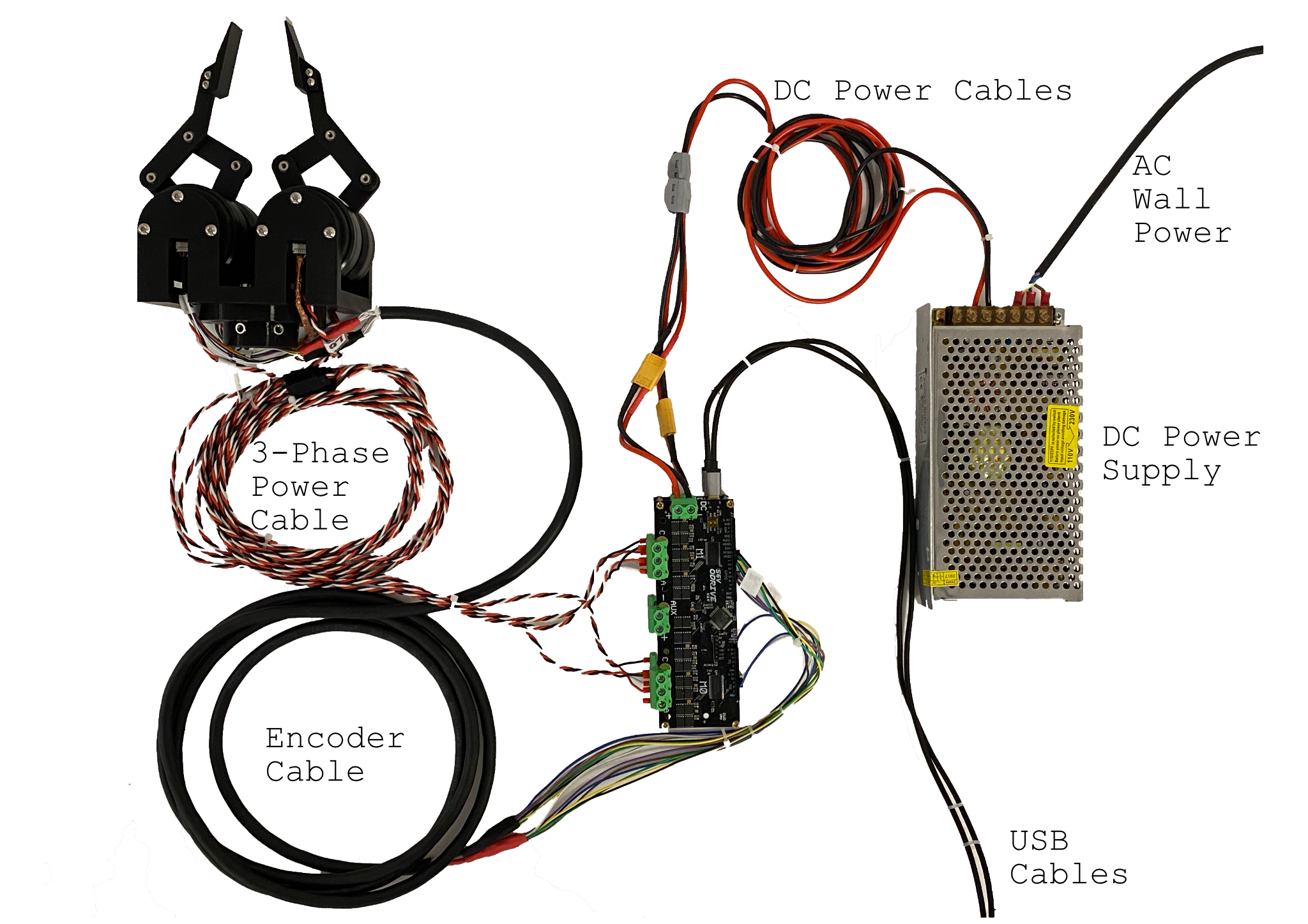
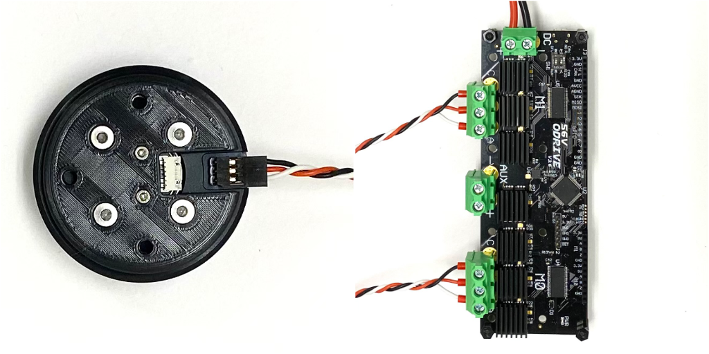
The components should be connected following the diagram below. The encoder connection (black) and power connection (green) will be further elaborated.
First connect the DC power supply to the wall plug. The brown, blue, and yellow wires correspond to L, N and Ground ports on the power supply. Then connect it to the two ODrive boards, positive to positive, negative to negative. There is no on/off button, plug in the wall plug to turn the system on, unplug to turn it off. Power it on does not arm the motors.
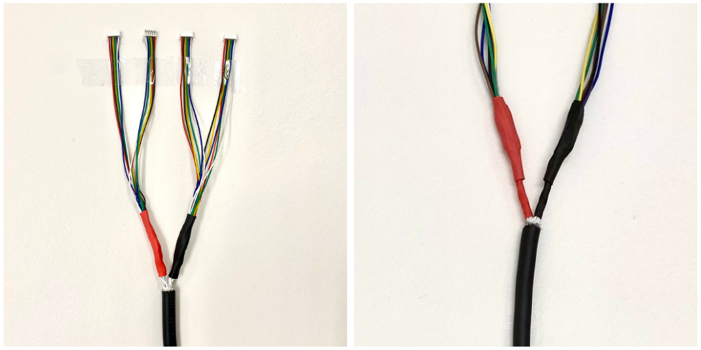
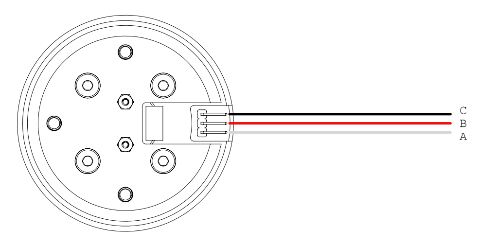
For the encoder connection, we fabricate a cable assembly as shown below in the schematic. It is recommended to verify the connectivity and resistance of each connection to make sure the cables are soldered properly. We also recommend to label each connector like the schematic.
After successful fabrication, connect the motor encoders and the ODrives.
For the power connection, the motors are matched with the ODrive axes as follows:
| Actuator | ODrive | Axis |
|---|---|---|
| R0 | ODrive_R | M0 |
| R1 | ODrive_R | M1 |
| L0 | ODrive_L | M0 |
| L1 | ODrive_L | M1 |
Keep the 3-phase connection consistent as shown below.
Each actuator module require calibration before use. This step can not be done after the gripper is assembled, so do not postpone this step.
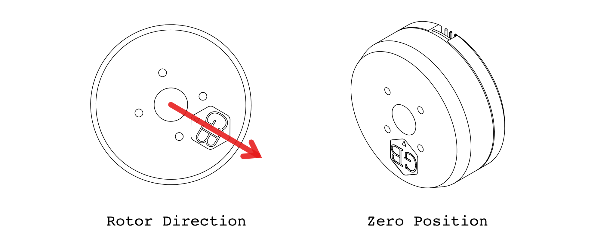
We explicitly define the direction of the rotor to be the direction the hexagonal logo on the rotor is pointing at, and the zero position of the motor to be when the direction of the motor is pointing at the opposite direction of the power port on the stator.
Execute the following command and follow its instructions in the terminal.
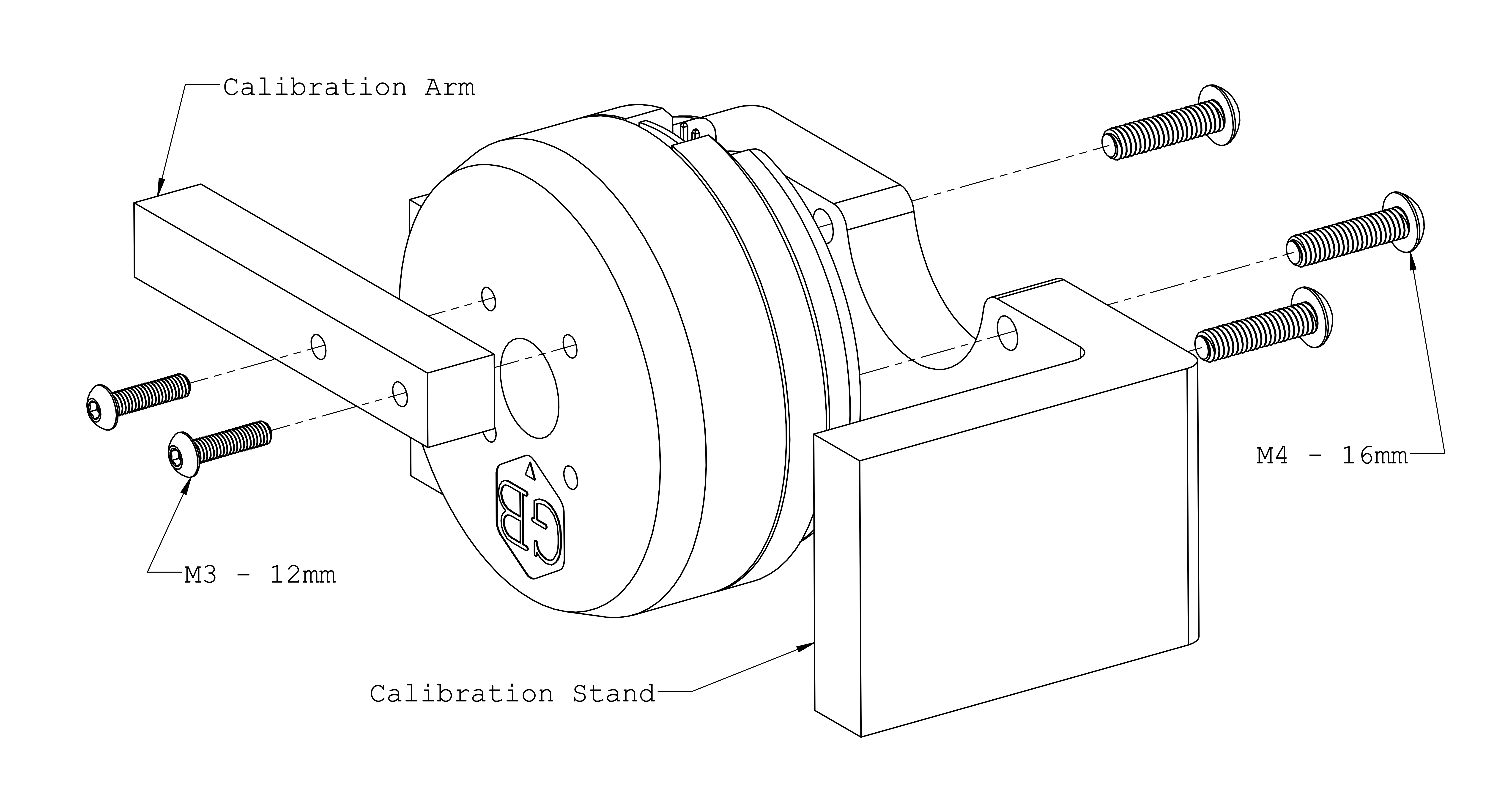
python3 -m ddh_driver.calib_odriveHere we calibrate the zero position of the motor. Mount the actuator on the calibration stand and install the calibration arm onto the actuator according to the diagram
Execute the following command to show real-time reading from the encoders.
python3 -m ddh_driver.check_encoderPut the motor into zero position as show in the diagram below. Press down the calibration arm to make sure the stand and arm touch tightly.
Record the encoder reading in configuration in ddh_driver/config/default.yaml. Perform this calibration for each actuator and record it in their respective keys in the configuration file.
motors:
  R0: # and R1, L0, L1:
    offset: the encoder reading at zero stop
After modifying the configuration file, execute the following command will show the real-time reading of the motor angular position in degrees.
python3 -m ddh_driver.check_motor_posIt should be zero when motor is in zero position. Also try 90° and 180°. Don't mind the sign at this stage of assembly.
The gripper assembly is complete. Please perform the following validation steps to make sure the linkages and actuators are installed correctly.
First check the association between proximal links and actuators. They should follow the diagram below exactly. If there is a mismatch, please go back to the assembly steps and correct the mistakes.
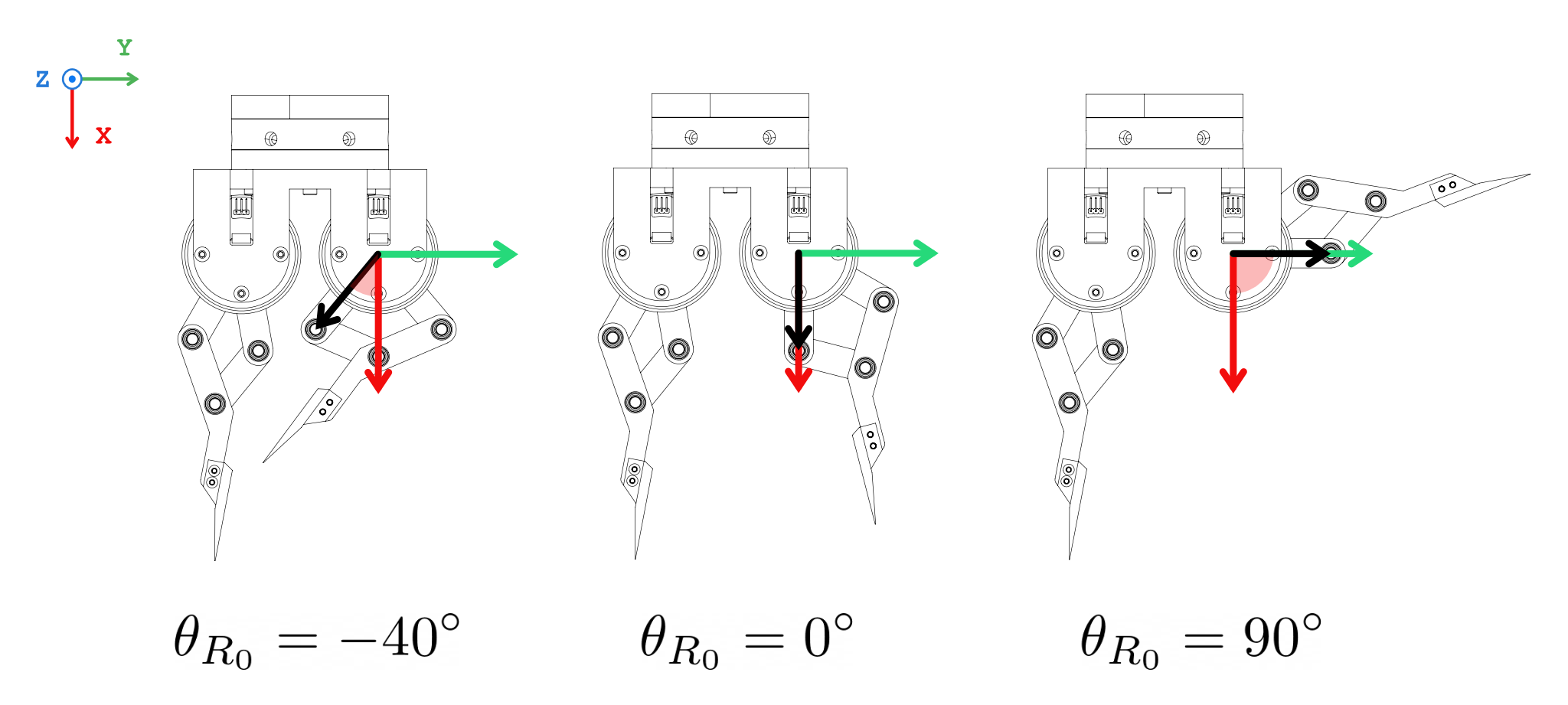
Then check the angular position of the four proximal links. This value will be referred to as θ, with subscript indicating which link. Execute the following command to print real-time reading of θ
python3 -m ddh_driver.check_thetaIt should be the angle between the link and the x-axis, in counter-clockwise direction. For example, the following figure shows the angle of R0 link at -40°, 0°, and 90°.
 If everything checked out at this point, you have successfully built and calibrated the direct-drive gripper.
If the default setup does not satisfy your requirements, it can be further customized.
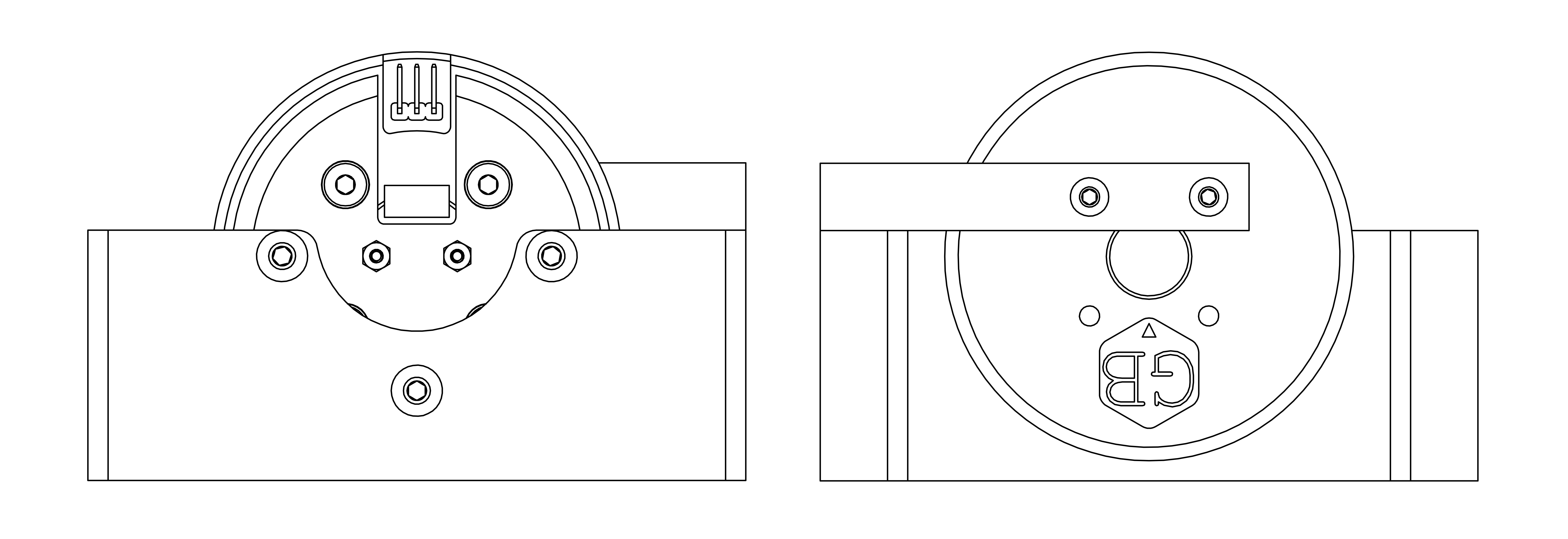
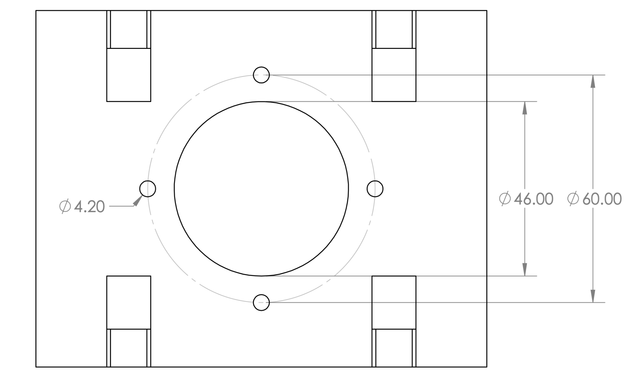
If the default mounting does not work for you, it's very easy to make a custom mount. The gripper has a 60 mm PCD with 4 ⨉ M4 mounting interface, as shown in the drawing below.
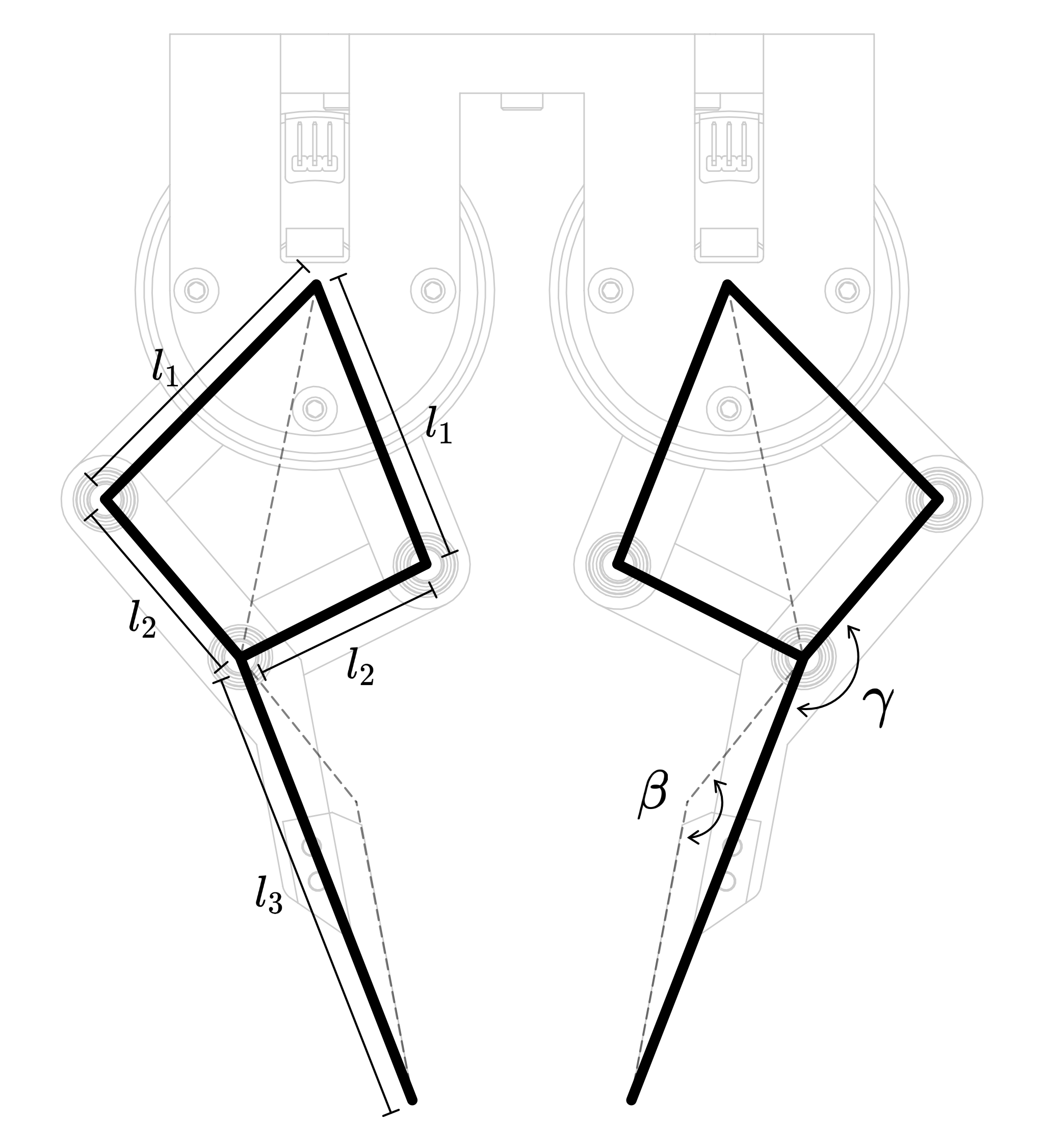
The geometrical parameters can be customized. After you design your custom parts, update the ddh_driver/config/default.yaml so the driver can work properly.
| Parameter | Configuration Path | Unit |
|---|---|---|
| ℓ₁ | /geometry/l1 |
mm |
| ℓ₂ | /geometry/l2 |
mm |
| ℓ₃ | /geometry/l3 |
mm |
| 𝝱 | /geometry/beta |
degree |
| 𝛄 | /geometry/gamma |
degree |
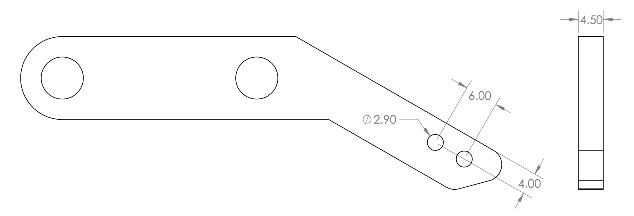
The fingertip is designed to be swappable. It is attached to the distal link, shown in the schematic below. The default fingertip has a sharp tip for scooping thin objects. Customize the fingertip for your specific scenario. Beware that ℓ₃ and 𝝱 change with the fingertip geometry, make sure to update them in the configuration file.
You have completed the assembly and calibration of the direct-drive gripper. To learn about how to use the gripper, please proceed to the ddh_driver for tutorials and documentation.
For any technical issues, please contact Pu Xu (pxuaf@connect.ust.hk)
