Guoxin Fang, Tianyu Zhang, Sikai Zhong, Xiangjia Chen, Zichun Zhong, Charlie C.L. Wang,
Updated: July-02-2021
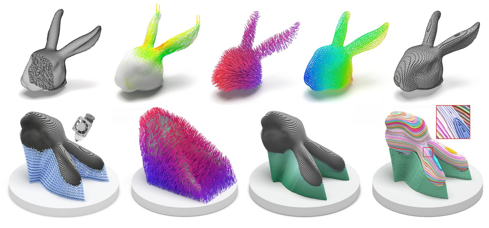
This is the code to slice the given model with curved 3D printing layers and generate a toolpath based on the stress distribution. The generated toolpath can be printed by the multi-axis 3D printer, which results in a higher strength in the fabricated model.
Please compile the code with QMake file 'ReinforcedFDM.pro'.
Tested platform:
macOS: QT Creator
Windows (recommand): Visual Studio + QT-plugin (tested QT version: 5.12.10 + msvc2017_64)
Remark: if you are using Visual Studio, after using QT VS Tool to open the .pro file and generate the project,
-
Set 'shapeLab' as the start up project
-
Enable OpenMP to get best performace at: ShapeLab Project Property -> 'Configuration Proerties' -> c/c++ -> Language -> Open MP Support -> Select 'Yes (/openmp)'
-
Open Console at: ShapeLab Project Property -> 'Configuration Proerties' -> Linker -> System -> Select 'Console (/SUBSYSTEM:CONSOLE)' in 'SubSystem'
-
QT verstion if you install a different qt version and meet with an issue open the UI after compile the project, you may first check and find 'Qt5Core.dll', 'Qt5Gui.dll', and 'Qt5Wdgets.dll' in the QT installed folder and add to '../shapeLab/release/' folder (Visual Studio will generate this folder after you compile the project). For Debug mode, you need to add 'Qt5Cored.dll', 'Qt5Guid.dll', and 'Qt5Wdgetsd.dll' to '../shapeLab/debug/' folder.
First input tetrahedral mesh into the system.
Three sample models are given 'Bunnyhead.tet', 'topopt_new.tet', and 'YogaNew.tet'. You can either drag the file into the blank area of the UI or open the panel "file -> open" and then select the model.
Step 1: Input FEA simulation result and compute principal stress direction as vector field by clicking bottom 'Step 1: Input FEA Result'.
-
The color map on the mesh visualize the stress distribution. You can draw the stress vector field by using the function "View -> Profile" or direct click the "Profile" bottom.
-
You can also change the percentage of the critical region by changing the value below 'Step 1: Input FEA Result' bottom and click 'Change ratio' to redraw the field. Notice the parameter used in our paper is already set as the initial value in UI.
Step 2: Compute Field (for both vector field and scalar field) by clicking bottom 'Step 2: Field Computing'. This process may take some time to compute the optimized field.
-
After finish computing the field, you can draw the scalar field by using the function "View -> Node" or direct click the "Node" bottom.
-
The vector field can be drawn by using the function "View -> Profile" or direct click the "Profile" bottom. (the previous stress field will be replaced).
Step 3: Slicing the model and generate curved layer by clicking bottom 'Step 3: Curved Layer Slicer'. You can change the Layer # with a different value on the right side.
- You will then have the curved layer in the UI. You can check each layer in the "Visual" panel by choosing different layer numbers or only draw a single layer by click 'Draw Single'.
Step 4: Compute vector field on each curved surface (for toolpath generation) by clicking ' Step 4: Compute Field on Iso-Surface'.
- Caution: Before run this process, please make sure you disable the drawing of the profile, otherwise the system will automatically draw the vector field on every layer (may take 1 min to draw this)!
Step 5: Split and output generated curved surface by clicking ' Step 5: Output Layer Below'. The curved surface will be installed at folder "./model/IsoSurface/ModelName/"
- This function will also split the surface into single pieces. For example, if one layer (No. 10) contains three regions, our code will output three .obj files named 1000.obj, 1001.obj and 1002.obj. You can output the entire surface without splitting by deselecting the checkbox 'split', however, the surfaces generated in this way cannot be used for the next step to compute the toolpath.
Step 6: Toolpath Generation by clicking 'Step 6: Toolpath Generation (New)'.
-
This process will take a long time as each layer will load into the system, compute scalar field & boundary distance field, and subtract the hybrid stress-aligned curved toolpath. Please make sure you enable OpenMP to accelerate the computing process. Normally it takes 2-3 mins to run the top-opt model on a 6-Core Intel CPU. By opening the Console you can also check the progress during the computing.
-
This process will also take more than 8GB of memory on your PC for the 'top-opt' and 'YogaNew' model, please make sure you have at least 16GB RAM to get the best performance.
-
After finish computing the toolpath, please enable drawing the toolpath by using the function "View -> Edge" or direct click the "Edge" bottom. you will also see all the toolpaths as a mesh visualized in the 'Model tree' panel. In the 'Visual' panel, you can click the bottom "Deselect all in model tree" and then select the layer you want to draw by clicking it in the Model tree.
-
Generated toolpath will be output in folder "./model/IsoSurface/'your-model-name'/toolpath/" as txt file. The toolpath is represneted as waypoints in format "x,y,z,nx,ny,nz".
-
The code for the fabrication enabling part in our work is still under construction ......
-
Please check the details of processing the waypoint and run motion planning of the multi-axis 3D printer in our latest work (also with Source Code):
Singularity-Aware Motion Planning for Multi-Axis Additive Manufacturing
Tianyu Zhang, Xiangjia Chen, Guoxin Fang, Yingjun Tian, and Charlie C.L. Wang. IEEE Robotics and Automation Letters, Presented at IEEE International Conference on Automation Science and Engineering (CASE 2021), Lyon, France, August 23-27, 2021
