The PLM Breakout Board, Shield and Shahara are compatible, simple and low-cost solutions for creating a DIY IOT project or developing consumer product using power line telecommunications. The breakout board and shield are compatible with Arduino development boards and the Shahara is a compact all-in-one solution combining MCU and powerline modem circuitry on one board.
Stack the shield on top of one of the many MCU development boards with the recognizable Arduino Shield footprint and you instantly have a smart node that can communicate to appliances, lighting, garage doors and sensors over thousands of feet of home 120/240 AC or DC power lines with no other wires required (nodes receive power from the same wires they communicate over). Nodes can be accessed over the internet via web browsers and or C++/Python/MATLAB/LabVIEW applications.
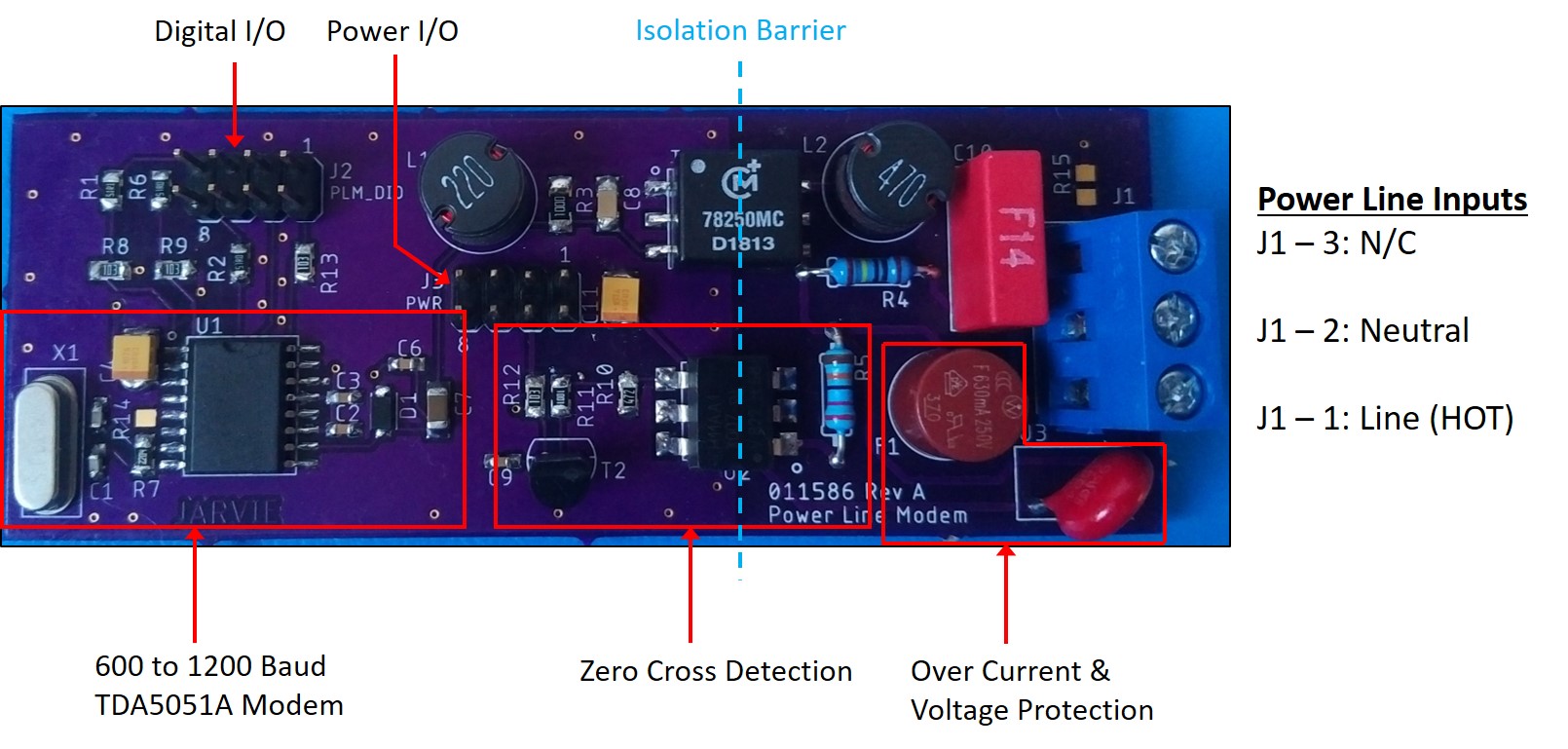
The breakout board does just that, it breaks out power line modem control and power signals to a header. This provides flexibility to control PLM communications from something other than an Arduino. This PLM solution is also a cheaper, bear-bones alternate, to the shield because it does not possess the AC to DC converter. This board functions similar to the NXP OM13313-598 Demo Kit but it's a fraction of the price. Like the OM13313 Demo Kit, this board does not receive power from the same wires it communicates over. The DC power required by the breakout board components must be supplied seperate from the power lines used for communications.
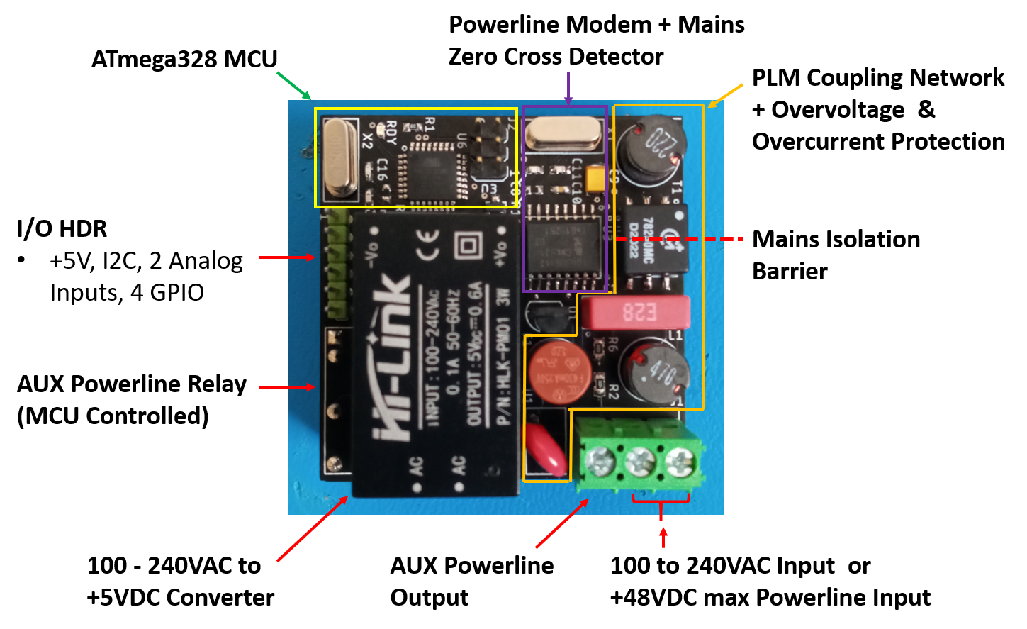
The Shahara is a standalone miniature PLM development board measuring 2" x 2"; perfect for embedding into DIY or prototype designs. It houses an onboard ATmega328p MCU for custom firmware development to create your custom smart home platform and or powerline smart home network. An onboard +5V AC/DC converter powers digital circuitry directly from the 120 or 240VAC input wires that the module(s) communicate over.
These power line modem solutions are compliant with US FCC (Federal Communication Commission), Industry Canada, Japan MPT, and European CENELEC EN50065-1 regulations for signaling in the 125 kHz to 140 kHz and the 95 kHz to 125 kHz frequency bands.

- Communicates over +35V max DC or home 120V/240V AC power lines using ASK carrier wave generation
- Provides power to MCU dev board and expansion shields from power line input (+7V @ 300 mA from VIN pin)
- AC Mains isolation via high-frequency transformer for safety
- Zero cross detection for system synchronization and or line frequency measurements
- 600 to 1200 bps UART bus between modem and MCU (Arduino TX0 and RX0)
- Modem baud rate adjustment via external clock input
- Modem output overload protection
- Automatic gain control at modem's receiver input
- Modem power down control to reduce power consumption
Purchase demo board or full kit

A DIY smart home system is one of the many things you can create with the PLM Shield. The figure below illustrates a smart home application. The Switch Node provides on/off control of appliances, lighting and or opening/closing of garage doors. The Environment Node can monitor the indoor air quality of areas within your home. The Internet Node can host a webpage that displays the environmental data, as well as, clickable buttons to control appliances, lighting or garage doors. The webpage can be accessed from any mobile phone, PC or tablet connected to the internet; allowing you to access your DIY smart home network from inside your house or while your away.

-
Internet Node: Ardunio UNO + PLM Shield + Ethernet Shield creates a node that can be controlled from outside of your home over the internet, host server applications to report data to a website for remote monitoring.
-
Environment Node: Ardunio UNO + PLM Shield + Adafruit BME680 Breakout creates a node that can monitor temperature, pressure, humidity and VOCs in a room/area within your home.
-
Switch Node: Ardunio UNO + PLM Shield + Relay Shield creates a node that can switch on/off AC appliances (e.g. fan, light, motor or high current DC actuators like solenoid valve)
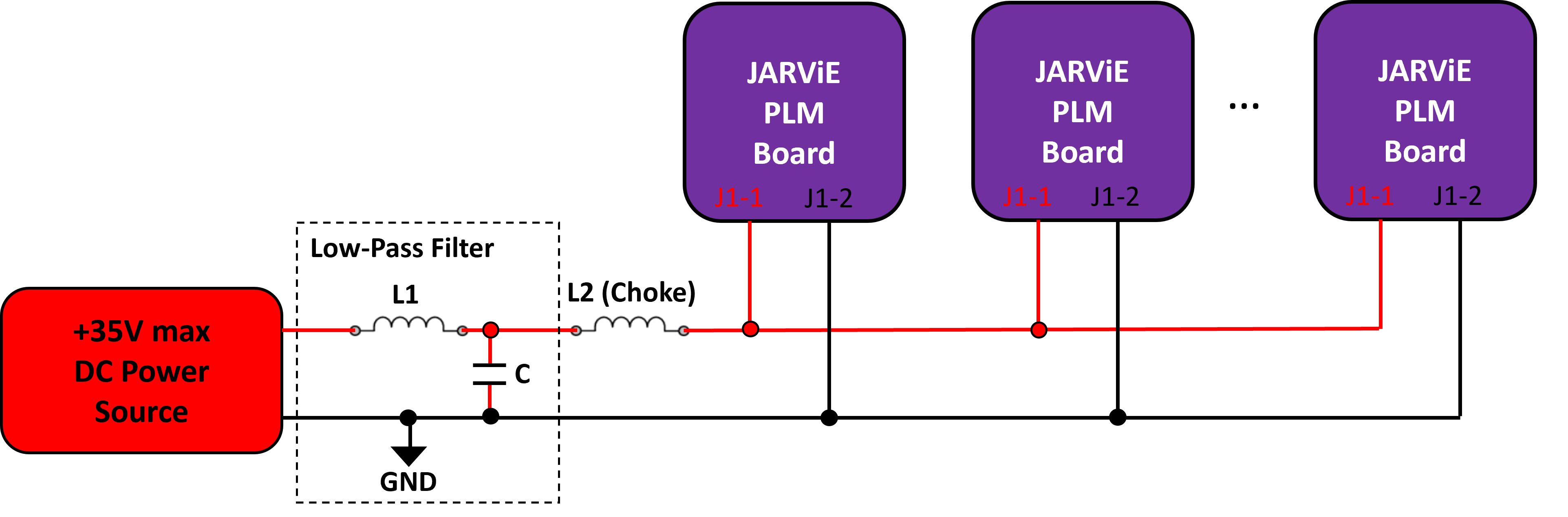
The following diagram illustrates how the PLM Shield should be connected to a DC power line. In this diagram, the DC power source can be a switch-mode power supply, solar panels with converted DC output, batteries, super capacitor, etc. The DC power source should not exceed +35 VDC.
When using a switch-mode power supply, it is best to filter the output to achieve the best powerline telecommunications. L1 = 100 uH and C = 470 uF is a low-pass filter that prevents power supply noise from interfering with powerline communications. The filtering components are likely not required when using batteries or capacitors as the power source.
The impedance of C decreases as freq. increases so a choke (L2 = 100 uH) is recommended to prevent the capacitor from overloading/shorting the 1200 Hz powerline communications. Using batteries and capacitors as the DC power source will have the same overloading affect, so a choke is recommended for these sources as well.
Powerline modem technology is being used in the solar, oil and gas and irrigation industries just to list a few. E-mail hilljarvis@gmail.com if you're interested and or need help planning, reviewing, designing, developing and or deploying a custom powerline modem device and or powerline communications system.
- Connect 120 or 240 AC power cord to PLM connector J1 per Table 3
- Repeat step 1 for a second PLM demo board.
- If you have the PLM Demo Kit and the firmware hasn't been updated, skip to step 6.
- Download the latest version of the Arduino IDE for your OS from the Arduino website.
- Download firmware from src directory of this repo.
- Program an Adafruit Metro or equivalent (e.g. OSEPP UNO, Arduino UNO) with the Power_Line_Modem_Slave.ino.
- Program a second Adafruit Metro or equivalent with Power_Line_Modem_Master.ino.
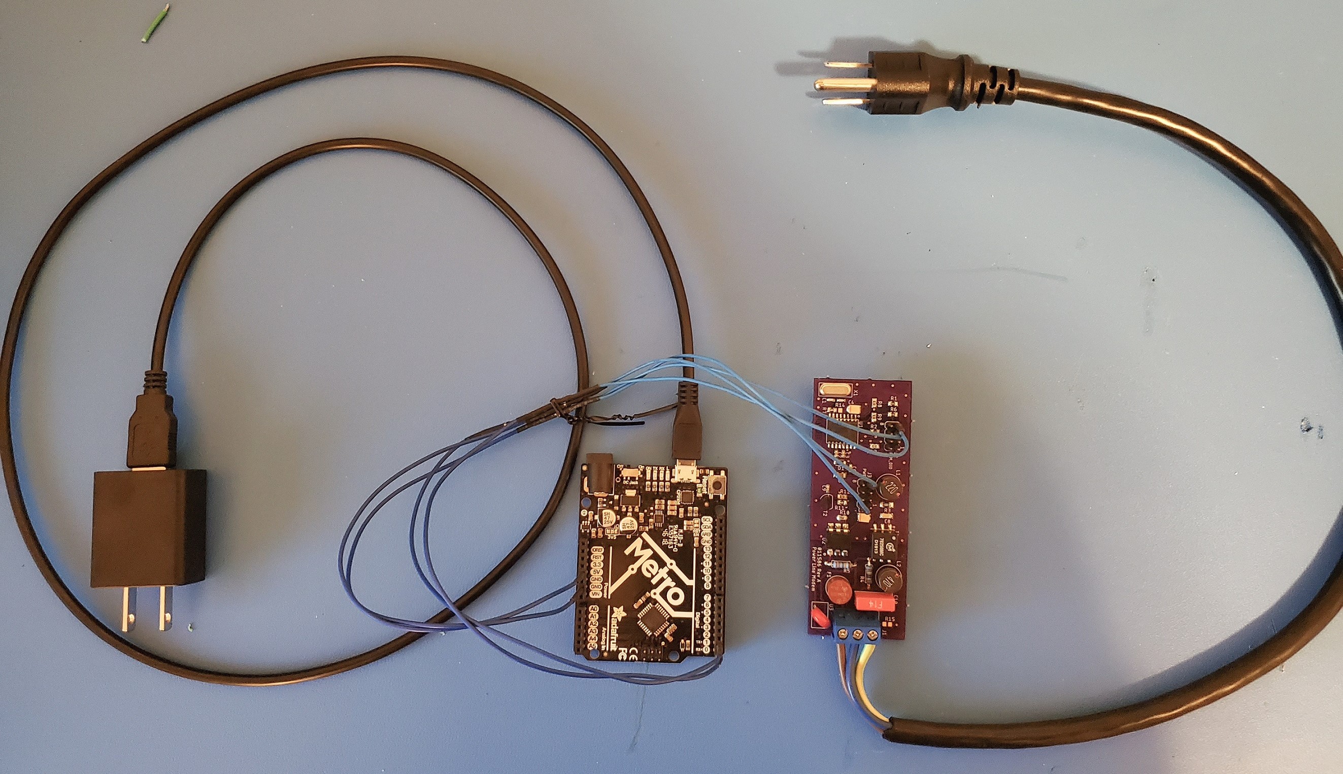
- Connect each Adafruit Metro to a JARViE PLM demo board per Table 4.
- Verify that power and ground connections between the Adafruit Metro and PLM are correct.
- Obtain a USB A to micro B or equivalent cable and a USB A wall adapter.
- Plug the micro B end of the USB cable into the Adafruit Metro.
- Plug the A side of the USB cable into the wall adatper.
- Verify that your PLM slave and master devices resemble the setup reference figure below.
- Verify that the AC power cord voltages are rated appropriately for the outlet you plan on plugging the PLMs into!
- Plug the AC power cord and wall adatper of the master device into a home outlet.
- Once powered, the Adafruit Metro of the master device should blink 4 times every 12 seconds. After the red LED blinks, the master transmits: ASCII command string "IDN?" + Fletcher16 16 bit checksum (5 ASCII characters) + "\n" EOL character to slave devices connected to the power line.
- Plug the AC power cord and wall adatper of the slave device into another home outlet.
- Within 30 seconds, the red LED on the Adafruit Metro of the slave device will blink 12 times every 12 seconds. The red LED blinks only when the "IDN?" command is received from the master device. Notice that if you disconnect the master from the power line, the red LED on the slave device will not blink as long as the master is disconnected.
| PLM DIO Pin | Description |
|---|---|
| 1 | Zero cross detector |
| 2 | Power down (active HIGH) |
| 3 | GND |
| 4 | PLM EXT CLK |
| 5 | PLM DATA_IN (active LOW) |
| 6 | GND |
| 7 | PLM DATA_OUT (active LOW) |
| 8 | PLM CLK OUT |
| PWR Pin | Description |
|---|---|
| 1 | GND |
| 2 | +5V |
| 3 | GND |
| 4 | +5V |
| 5 | GND |
| 6 | +5V |
| 7 | GND |
| 8 | +5V |
| J1 Pin | AC/DC signal |
|---|---|
| 1 | AC LINE/DC_IN+ |
| 2 | AC Neutral/DC_IN- |
| 3 | N/C |
| Adafruit Metro Pin | PLM Breakout Board Connector Pin |
|---|---|
| +5V | J3 pin 2,4,6, or 8 |
| GND | J3 pin 1,3,5 or 7 |
| TX0 | J2 pin 5 |
| RX0 | J2 pin 7 |
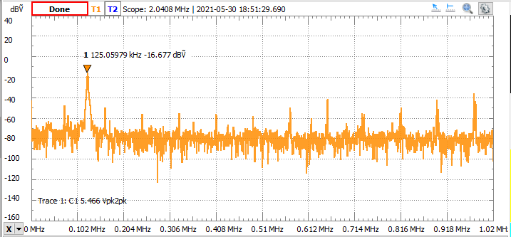
All JARViE boards are set to brodcast powerline communications at 125 kHz. Here's a spectrum capture of a PLM Shahara plugged into a home outlet in North America. Note the signal magnitude at 125 kHz. Also realize the signal magnitudes at other frequencies relative to the communications frequency. For good powerline communicaions, the SNR (signl-to-noise ratio) of the communications frequency compared to surrounding frequencies (communications +/- 200 kHz) should be as large as possible.
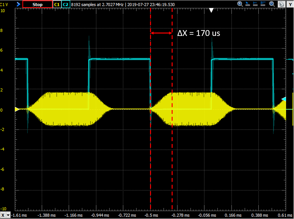
The following image shows the DATA_IN to Tx carrier output delay. The blue trace is a 1 kHz square wave driving the PLM's TDA5051A modem DATA_IN input. The yellow trace is the modulated ASK carrier wave transmitted to all PLMs on the power line network. The capture shows that there is approximately a 170 microsecond delay between setting the DATA_IN input and Tx carrier wave generation.
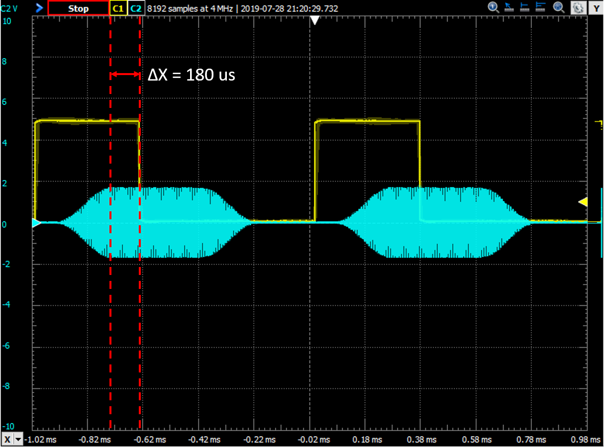
The following image shows the Rx carrier input to DATA_OUT output delay. The blue trace is the modulated ASK signal received through the AC inputs on the JARViE PLM. The yellow trace is the digital TDA5051A DATAOUT signal that can be interpreted with an MCU or equivalent UART compliant device. The capture shows that there is approximately a 180 microsecond delay between Rx carrier wave reception and the DATAOUT output.
The main purpose of the PLM zero cross detection circuitry (ZCD) is to provide a method to synchronize devices to one another. The intent is to not have to share a clock between devices that are meters away. The output of the ZCD goes from 0 to +5V making it compatible with MCUs. By pairing the PLM with an MCU, the ZCD output can be used to trigger event timers, create task schedulers within a PLM network and or send messages when noise on the power line is smallest for best communication results (zero crossing point). The ZCD can also be used to measure the frequency of the AC power line.

- A – 120 VAC zero cross point. Signal begins to rise to maximum amplitude but H11AA1 bi-directional optocoupler is off so zero cross signal remains HIGH (+5V) due to pull-up resistor.
- B – 120 VAC rises high enough to bias NPN transistor in optocoupler pulling the zero cross detection signal LOW (0V).
- C – 120 VAC zero cross point. Signal begins to fall to minimum amplitude. H11AA1 optocoupler is off so zero cross signal remains HIGH (+5V) due to pull-up resistor.
- D – 120 VAC falls low enough to bias NPN transistor in bi-directional optocoupler pulling the zero cross detection signal LOW (0V).