This repository contains the source code and build system for the
MCTrace binary instrumentation tool. The MCTrace tool enables users
to modify binaries, inserting instrumentation into them in order
to collect fine-grained tracing information. This document covers
instructions for building MCTrace from source for development or
releases. For information on the MCTrace tool's design and usage, please
see MCTRACE.md.
MCTrace can be built for one of two purposes: either for local development in a Haskell build environment, or for release as a Docker image. Instructions for each method are provided below.
The development environment setup and build processes are automated. System requirements for building mctrace are as follows:
- OS: Ubuntu 20.04, 64-bit
- Disk: 100 GB
- RAM: 16 GB
To perform a one-time setup of the development environment including the
installation of LLVM, cross compilers, and other required tools, run the
development setup script. This script requires sudo privileges since
it installs system packages.
./dev_setup.sh
Once the development environment is set up and the required tools are installed, MCTrace can be built with the build script:
./build.sh
After the build has completed, various cross compilers and other tools
can be brought into the PATH for easier access with:
. env.sh
To build the example test programs for x86_64 and instrument them
using various testing probes, run:
make -C mctrace/tests/full
To do the same for PowerPC, run:
make -C mctrace/tests/full ARCH=PPC
The mctrace tool can be run manually by running:
cabal run mctrace <args>
For more details on using the mctrace tool, see MCTRACE.md.
To build the release Docker image, execute the following from the root of the repository:
cd release
./build.sh
This will build two docker images:
-
mctrace.tar.gz, a self-contained image that contains MCTrace, its dependencies, associated tools, and examples. For information on using this image, please seerelease/README.md. -
mctrace-tool.tar.gz, a minimal image containing just MCTrace and its dependencies. A helper script,release/mctrace, has been provided to run the command in a container based on this image. Note that paths passed to this script must be relative to the root of the repository and paths outside of the repository will not accessible.
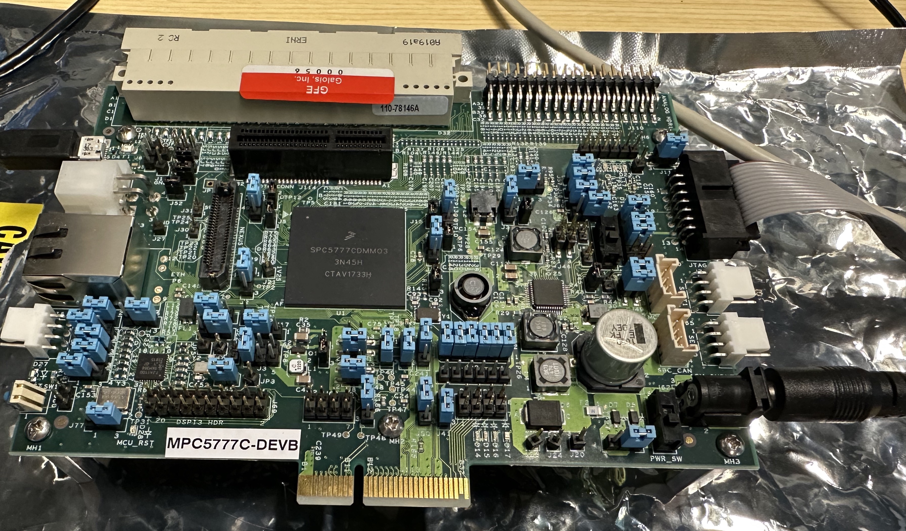
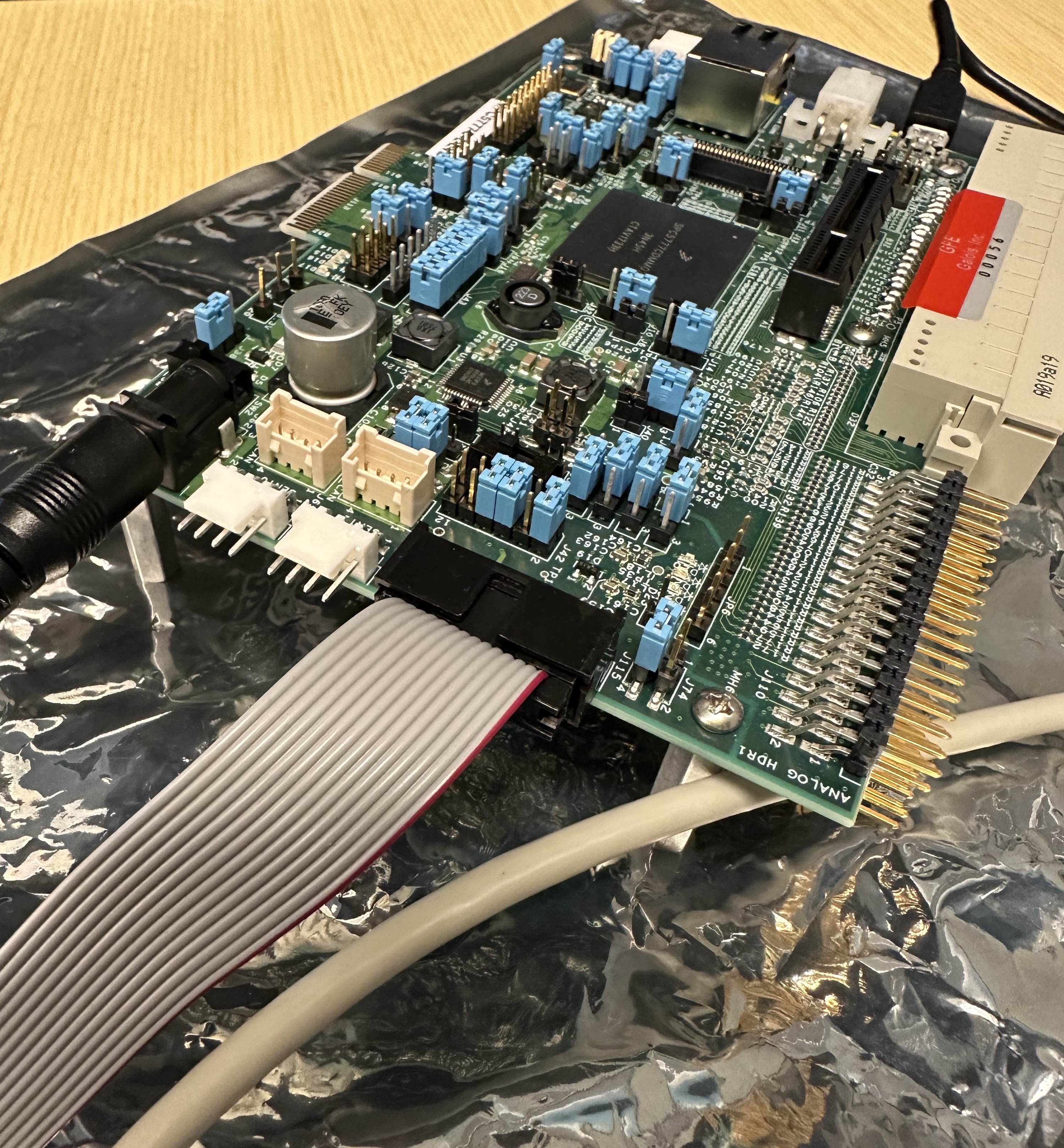
Some of the work on this project involved attempting to run the Challenge Problem 10 binary on a real PowerPC microcontroller. We obtained an NXP development board, the MPC5777C, and a PEMicro USB Multilink debug adapter for connecting to the board. This work involved flashing the microcontroller with the Challenge Problem 10 binary, both original and instrumented versions, under the following conditions:
- NXP S32 Design Studio for Power Architecture, version 2.1
- IBM Thinkpad running Ubuntu 16.04, a supported platform for the NXP Design Studio
- PEMicro USB Multilink adapter, model USB QORIVVA Multilink for MPC55xx/56xx devices, part # USB-ML-PPCNEXUS
- USB A to USB micro connector for the MPC5777C debug UART
The system installation was done as follows:
- Install Ubuntu 16.04 with a desktop GUI installed.
- Install S32DS 2.1, following the steps in the S32 Design Studio for Power Architecture 2.1 Installation Guide.
The flashing procedure was performed by following the steps listed in the Immunant challenge problem repository and are reproduced below for posterity. Steps for the booting procedure are also documented below.
In our attempt to flash the MPC5777C with the Challenge Problem 10 binary, our findings and next steps were as follows:
- We were able to use the flashing procedure to load the uninstrumented (original) Challenge Problem 10 binary for MPC5777C onto the board.
- Our evidence that an unmodified Challenge Problem 10 binary booted somewhat successfully was that we saw the following output on the UART console:
Setup Complete.
ERROR: Failed to send status update
- We then flashed an
mctrace-instrumented version of the Challenge Problem 10 binary. The instrumented version that we found, along with its probes, can be found in thecp10_demo/mpc5777cdirectory in this repository. - Our instrumented version failed to boot (as evidenced by no console output).
- Even with a platform implementation that does nothing in any of its
functions (e.g.
platform_send) and even with probes that do not use any global variables (thus not warranting a memory allocation from the platform implementation to provide for global variable storage), the binary failed to boot. We did not explore this further to determine the cause. - However, one key task left unfinished in our work was to write a suitable platform implementation for the MPC5777C. To date, we had used a PowerPC platform implementation that was only suitable for running in Linux userspace environments. To get a working platform implementation on the MPC5777C, an exfiltration mechanism must be implemented, such as a CAN bus send operation or a UART write. A next step is to obtain either of those and integrate their source directly into the compilation process of the MPC5777C platform implementation.
This section details how to connect the PEMicro adapter to the MPC5777C, since there is no suitable documentation on how to get this right.
This image shows the board at a glance, with the power connector and power switch visible in the lower right corner of the board. The USB UART is connected at the far left part of the board and the PEMicro debugging adapter's ribbon cable is connected on the right with the red stripe (Pin 1) positioned furthest from the power connector.
This image shows the PEMicro adapter with its ribbon cable coming from its enclosure.
This image shows how the PEMicro adapter's ribbon cable connects to the MPC5777C, with the red stripe position indicating Pin 1.
This image shows how the ribbon cable is connected to the internal header in the PEMicro adapter. Of all of the headers available, two fit the provided 14-pin cable. The correct header is the lower-left header, pictured here, and the Pin 1 orientation is the lower-right pin of the header if looking at the board from above.
Source: Immunant AMP Challenge Problem repository
- Right click in the Project Explorer tab within S32DS.
- Click "Import".
- In the Import window, navigate to "S32 Design Studio" > "Executable File Importer".
- Click "Next".
- Click "Browse" and navigate to your binary of interest.
- Under "Please specify hardware parameter ...",
- navigate to "MPC5777C" > "MPC5777C" > "Z7_0" for the core selection.
- Click "Next".
- Specify a project name and rename the launch configuration if desired.
- Click "Finish".
With the project created, you can then navigate in project explorer to the project. Navigate to "{Project Name}" > "Binaries" > "{Binary Name}". Right click on "{Binary Name}" and then click "{Flash from file}".
If there are no launch configurations, click on the "New launch configuration" button, which will create a new configuration based on the binary's name. Otherwise, you can use one of the flash configurations if there is one already populated for the MPC5777C. This may happen if you have created other projects.
Select the desired configuration (likely just created), and click on the
"PEMicro Debugger" tab. For "Interface" select the USB Multilink...
option. For port, select the port that the Multilink is connected to.
Likely some COMX type variant. For "Device Name", be sure MPC5777C
is selected and Z7_0 for "Core". Default options should work for the
rest. Click "Flash".
A similar workflow should be possible by selecting the project, right-clicking "Debug as" or "Runs as" after the above steps and selecting "S32DS C/C++ Application". This, however, was not tested as of writing this document.
- Plug in the power adapter.
- Connect a USB micro cable to the debugging UART USB connector on the left side of the board (the opposite end from the power connector).
- On the Linux host to which the USB UART is connected, run
sudo minicom -D /dev/ttyUSB0to connectminicomto the UART. - Flip the power switch (the switch immediately next to the power connector).
This material is based upon work supported by the United States Air Force AFRL/SBRK under Contract No. FA8649-21-P-0293, and by the Defense Advanced Research Projects Agency (DARPA) and Naval Information Warfare Center Pacific (NIWC Pacific) under Contract Number N66001-20-C-4027 and 140D0423C0063. Any opinions, findings and conclusions or recommendations expressed in this material are those of the author(s) and do not necessarily reflect the views of the DARPA, NIWC Pacific, or its Contracting Agent, the U.S. Department of the Interior, Interior Business Center, Acquisition Services Directorate, Division III.
SBIR DATA RIGHTS
Contract No. 140D0423C0063
Contractor Name: Galois, Inc.
Contractor Address: 421 SW Sixth Ave., Suite 300, Portland, OR 97204
Expiration of SBIR Data Protection Period: 06/07/2042
The Government's rights to use, modify, reproduce, release, perform, display, or disclose technical data or computer software marked with this legend are restricted during the period shown as provided in paragraph (b)(5) of the Rights in Noncommercial Technical Data and Computer Software-Small Business Innovation Research (SBIR) Program clause contained in the above identified contract. After the expiration date shown above, the Government has perpetual government purpose rights as provided in paragraph (b)(5) of that clause. Any reproduction of technical data, computer software, or portions thereof marked with this legend must also reproduce the markings.
(c) 2022-2024 Galois, Inc.


