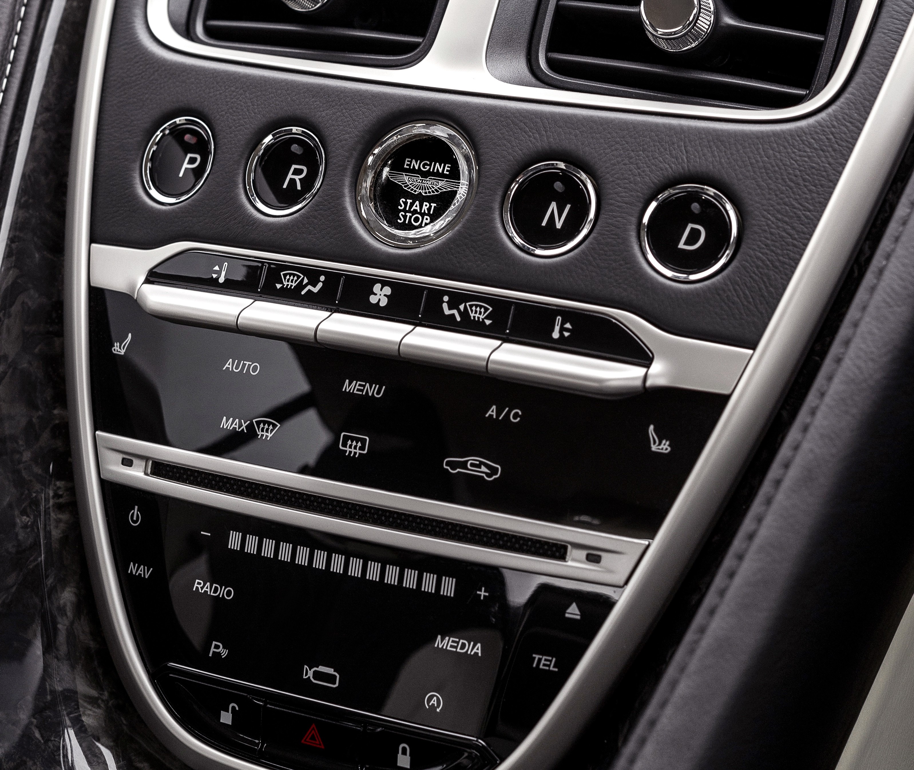
This is to introduce drive-by-wire buttons for Mercedes-Benz. Specifically, it is for my Mercedes-Benz SLK55 AMG.
- Fingerprint scanner instead of Start button
- Software function
- Pin layout
- Source code
- Updates
- Update Sun 2 May 2024
- Update Sun 3 May 2024
- Update Sun 4 May 2024
- Update Sun 5 May 2024
- Update Sun 6 May 2024
- Update Sun 8 May 2024
- Update Sun 9 May 2024
- Update Thu 27 Jun 2024
- Update Sun 30 Jun 2024
- [Update Mon 1 Jun 2024(#update-mon-1-jun-2024)
- [Update Sat 6 Jul 2024(#update-sat-6-jul-2024)
- Additional information
Instead of the start button (which would be really cool, but isn't feasable due to the way the EIS - Electronic Ignition Switch - works with the rest of the car), I'm putting a panel mounted fingerprint scanner instead. So this will double as an extra security feature.
The idea is to put the key fob in, turn it to position 2 ("ignition on"), but if anyone tries to turn the key fob to position 3 ("start") without a valid fingerprint, nothing would happen. This because there's a relay between the "start" cable and the rest of the car that is default open.
To be able to start the car, a valid fingerprint must be entered, the device will authorize this, and then close this relay, allowing the car to start.
HOPEFULLY, I can also send the same trigger signal that the EIS would send from the device.
At any point, if there is a fail, set the RED LED blinking and stop further program execution.
-
Bootup process.
- Light status LED (RED). -> BOOTUP STARTED
- Initiate CAN bus connection. Q: How to test connection?
- Send message to IC: "Starting Drive-By-Wire system".
- Initiate fingerprint scanner connection.
- Send message to IC: "Initializing Fingerprint Scanner".
- Login to and unlock the fingerprint scanner. CodeFunction:
VfyPwd - Validate talking to the correct fingerprint scanner.
- Do handshake. CodeFunction:
HandShake. - Check if sensor is normal. CodeFunction:
CheckSensor. - Check correct random string in the Notepad buffer. CodeFunction:
ReadNotepad. - Light fingerprint scanner LED (PURPLE). CodeFunction:
AuraLedConfig.
- Do handshake. CodeFunction:
- Send message to IC: "Fingerprint scanner initialized".
- Initiate and test actuator connection and control.
- Send message to IC: "Initializing actuator".
- Get status (current position) of actuator.
- LOOP: Check actuator connection and function.
- Get speed status from CAN. Q: How to double-check??
- Get break pedal status from CAN. Q: How to double-check??
- If ('not moving' && 'break pedal pressed') OR ('P'selected):
- Move actuator back 1mm.
- Validate correct movement.
- Move actuator forward 1mm.
- Validate correct movement.
- Check that "before test" and "current position" is the same.
- Move actuator back 1mm.
- else: restart loop.
- Send message to IC: "Actuator initialized".
- Light current drive button locator LED.
- Light status LED (YELLOW). -> BOOTUP DONE + LOGIN STARTED
-
Check authorization.
- Send message to IC: "Authorizing use".
- Check valet mode.
- If false:
- Verify fingerprint
- If not verified:
- Light status LED (RED). -> FAILED LOGIN
- Light fingerprint scanner LED (RED/FLASH). CodeFunction:
AuraLedConfig. - If attempts >= 3: sleep for 5min.
- else: restart loop.
- else:
- Turn off fingerprint scanner LED. CodeFunction:
AuraLedConfig. - Light status LED (GREEN). -> LOGIN DONE + MAIN LOOP STARTED
- Turn off fingerprint scanner LED. CodeFunction:
- If not verified:
- Verify fingerprint
- else:
- Light status LED (BLUE). -> LOGIN DONE + MAIN LOOP STARTED
- If false:
- Close EIS relay #1 (ignition switch). Q: What if power loss??
- Close EIS relay #2 (steering lock). Q: What if power loss??
- Send message to IC: "Use authorized, welcome <user|valet>".
- Send "start car" voltage signal to SAM.
-
LOOP: Wait for drive button press.
- If moving:
- If true: ignore button press (restart loop).
- If break pedal is pressed:
- If false: ignore button press (restart loop).
- If NEW button != CURRENT button.
- Get current position of actuator.
- Blink NEW drive button telltale LED.
- Move actuator to new position (synchronous).
- Get current position of actuator.
- Check that "before change" and "current position" have changed.
- Turn off CURRENT drive button telltale LED.
- Set NEW drive buttons telltale LED.
- If moving:
Q: How can the DriveByWire, SmartTOP and SprintBooster all be
set in valet mode all at the same time?
Q: Can DriveByWire check CAN for certain buttons around the car
to be pressed in sequence just like GhostImmobiliser??
| Pin | Port | Use | - | Pin | Port | Use |
|---|---|---|---|---|---|---|
| 1 | GPIO 0 | Button (Switch - N) | - | 40 | VBUS | |
| 2 | GPIO 1 | Button (Switch - D) | - | 39 | VSYS | |
| 3 | GND | - | 38 | GND | ||
| 4 | GPIO 2 | Button (Switch - P) | - | 37 | 3V3_EN | |
| 5 | GPIO 3 | Button (Switch - R) | - | 36 | 3V3_OUT | |
| 6 | GPIO 4 | Debug (TX) | - | 35 | ADC_VREF | Actuator - +5V |
| 7 | GPIO 5 | Debug (RX) | - | 34 | ADC2 | |
| 8 | GND | - | 33 | AGND | Actuator - GND | |
| 9 | GPIO 6 | Button (Telltale - P) | - | 32 | ADC1 | |
| 10 | GPIO 7 | Button (Telltale - R) | - | 31 | ADC0 | Actuator - Potentiometer Brush |
| 11 | GPIO 8 | Button (Telltale - N) | - | 30 | RUN | |
| 12 | GPIO 9 | Button (Telltale - D) | - | 29 | GPIO 22 | EIS Relay (#3 - start) |
| 13 | GND | [GPIO 29] | - | 28 | GND | [GPIO 23] |
| 14 | GPIO 10 | Actuator - Motor Relay (#1) | - | 27 | GPIO 21 | CAN #0 (RX) |
| 15 | GPIO 11 | Actuator - Motor Relay (#2) | - | 26 | GPIO 20 | CAN #0 (TX) |
| 16 | GPIO 12 | Actuator - +5V/+12V select | - | 25 | GPIO 19 | EIS Relay (#1 - steering lock) |
| 17 | GPIO 13 | Fingerprint Scanner (WAKEUP) | - | 24 | GPIO 18 | |
| 18 | GND | [GPIO 25] | - | 23 | GND | [GPIO 24] |
| 19 | GPIO 14 | Status LED (Data OUT) | - | 22 | GPIO 17 | Fingerprint Scanner (TX) |
| 20 | GPIO 15 | Status LED (Data IN) | - | 21 | GPIO 16 | Fingerprint Scanner (RX) |
LED | GPIO 25
Olimex RP2040-PICO30-16 also exposes GPIO 23-25, 29 by sacrificing four GROUND pins.
The different uses are specifically this way, because I need to consider UARTs/PIOs/ADC etc, and which pins they have connected to them. So it's not as .. "pretty" and simple as just throwing them in there and start using the ports..
- 4x Buttons (Switch)
- 4x Button LEDs (Telltale)
- 1x GND
=> 9-pin
- 2x Status LED (Data IN+OUT)
- 1x 3V3
=> 3-pin
Or those two combined, buttons and their LEDs and the status LED.
- 1x WAKEUP
- 2x Data (TX+RX)
- 1x GND
- 1x 3V3 (power)
- 1x 3V3 (touch induction power)
=> 6-pin
- 1x Control #2 (steering lock)
- 1x Control #3 (start signal)
- 1x 5V
- 1x GND
=> 5-pin
- 1x Actuator (Potentiometer Brush)
- 1x Actuator (Motor Relay +)
- 1x Actuator (Motor Relay -)
- 1x ADC 5V
- 1x ADC GND
=> 5-pin
- 1x CAN-L
- 1x CAN-H
=> 2-pin
33 leads out from system - 26, counting only unique pins (IgnitionSwitch "relay" and CAN#2 not counted, because those shouldn't be anyway).
Pin on the big motherboard connector and where it goes..
- 2: GND (for Actuator Motor GND)
- 4: +12V (for Actuator Motor +12V)
- 6: +5V (for Actuator Motor +5V)
- 10: ACTUATOR/MOTOR-RELAY_PLUS (signal control)
- 12: ACTUATOR/MOTOR-RELAY_MINUS (signal control)
- 14: ADC_VREF (signal)
- 16: ADC_GND (signal)
- 18: ACTUATOR/POTENTIOMETER-BRUSH (signal control)
- 20: ACTUATOR/VOLTAGE-RELAY_SELECT (+5V/+12V) (signal control)
=> 10-lead
- 2: GND (for relay GND)
- 8: +3V (for relay +3V)
- 22: EIS/START (signal control)
- 24: EIS/STEERING-LOCK (signal control)
=> 4-lead
- 2: GND (for status LED and fingerprint scanner GND)
- 4: +12V (for button locate LEDs)
- 6: +5V (for status LED +5V)
- 8: +3V (for fingerprint scanner +3V)
- 26: FP/TX (signal control)
- 23: FP/RX (signal control)
- 17: FP/WAKEUP (signal control)
- 21: STATUS_LED/IN (signal control)
- 19: STATUS_LED/OUT (signal control)
- 15: BUTTON_LED/D (signal control)
- 13: BUTTON_LED/N (signal control)
- 11: BUTTON_LED/R (signal control)
- 9: BUTTON_LED/P (signal control)
- 7: BUTTON/D (signal control)
- 5: BUTTON/N (signal control)
- 3: BUTTON/R (signal control)
- 1: BUTTON/P (signal control)
=> 16-lead
- 27: CAN-L (signal control)
- 25: CAN-H (signal control)
=> 2-lead
Crossed out parts are things I either didn't buy or don't need. Yet. Which is why I'm leaving them, but cross them out.
I'm saving the list of components for the PCB in a project list at Mouser. It's still a work in progress, so not quite correct yet.
| Part | Price |
|---|---|
| Actuator w/ feedback (potentiometer) | £115 ($145) |
| Aston Martin drive select buttons | £35 (*4 = £140) |
| Part | Price |
|---|---|
| Raspberry Pi Pico (w/ headers) | £5 |
| DC-DC Buck Converter 7-24V to 5V 4A | £5 |
| Fingerprint scanner (panel mount) | £23 |
| MOSFET Power Controller | £4 * 3 |
| NeoPixel Diffused 5mm LED | £5 |
| LED holder 5mm | £1 |
| Part | Price |
|---|---|
| TJA1055T/1J Fault-tolerant CAN chip | £2 |
| MCP2513FDTE/SL CAN Interface IC | £2 |
| DC Power Connector | £1 |
| Resistor - 1kΩ | £0.10 * 7 |
| Resistor - 10kΩ | £0.09 |
| Capacitor - 150pF | £0.08 * 2 |
| Resonator - 16MHz/15pF | £0.30 |
Don't think I'm going to buy the panel and wire to panel connectors. The motherboard connector looks quite big, so it might be better to just stick that out through the box. I'll leave them in here for now, because I might change my mind.
I want this thing to be as small as possible, easier to hide it somewhere in the car then :). I have yet to decide if I want a vertical or a horizontal connector..
Actually, I found a nice connector on eBay (IP68 Aviation Plug Socket for £21 (which is a bit much, but it's nice! :). It's quite big, but think it'll be nice to be able to lock the connector tight. It doesn't technically need to be water proof, but it can get moist in the cabin..
For now, I think that's the best option. This allows me to use a ribbon cable between the motherboard and that chassis connector, which minimizes the size of the motherboard connector.
These aren't things needed, but maybe I'll have a need for them one day..
The Pico is for development. Makes things easier when it's in a bigger format. However, some of these below might be used for the actual "production" device. But to get all the GPIO needed, an I2C GPIO expander (see above) would be needed.
Some of the signals I need will probably be to fast for the I2C bus, so those would have to come in through the board GPIO, not the I2C GPIOs. But then, the whole setup will be bigger anyway (because of the expander), so might just stick with the Pico anyway. Besides, the whole circuit board is (going to be) about the size of my palm anyway.
| Part | Price | Note |
|---|---|---|
| Seeed XIAO RP2040 | £6 | 11 GPIO pins |
| Tiny 2040 | £12 | 12 GPIO pins |
| Waveshare RP2040 Tiny | £5 | 20 GPIO pins |
As can be seen from the pin layout, I need more than this! At the moment, I have TWO GPIO to spare (and two GPIO/ADC) of the 26 pins that the RPi's have!
I might even have to go with the Olimex RP2040-PICO30-16 which have an additional four GPIO pins by sacrificing four GROUND pins..
But seems like the design have stabilized now. UNLESS the CAN bus adapters I'm going to have to get need more than TX/RX. Don't know which ones to get yet, still work in progres.
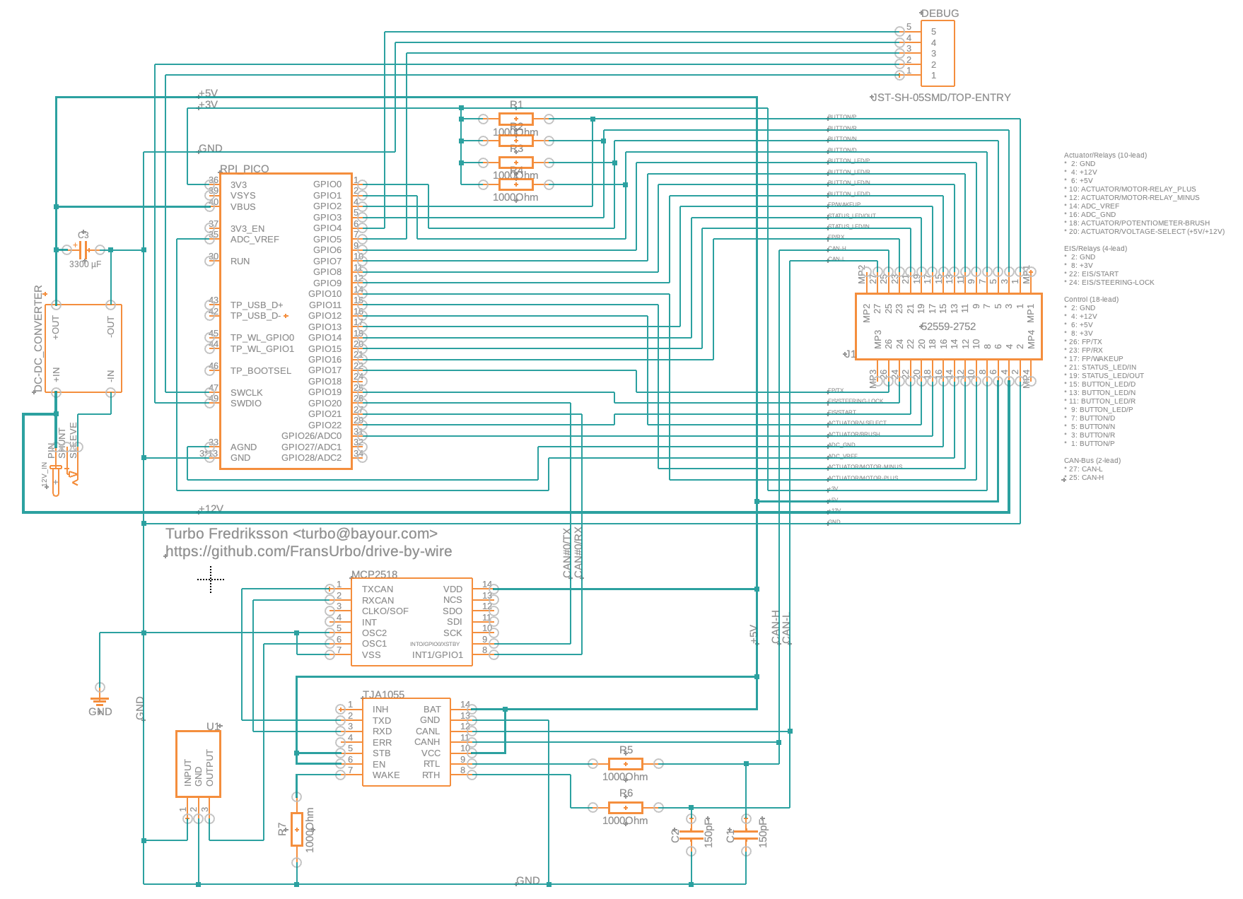
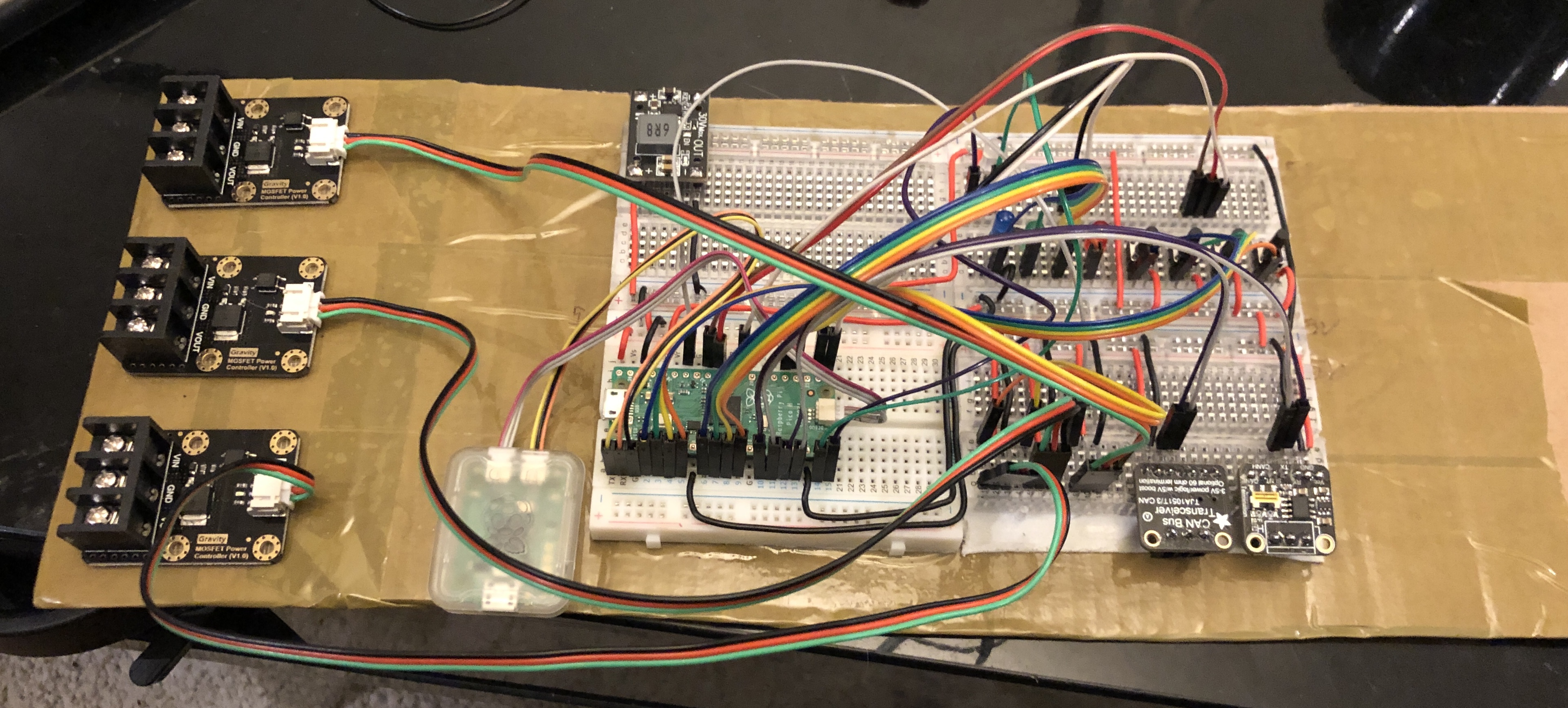
This is still work in progress, but this looks about right. That's what I've wired on the breadboard.
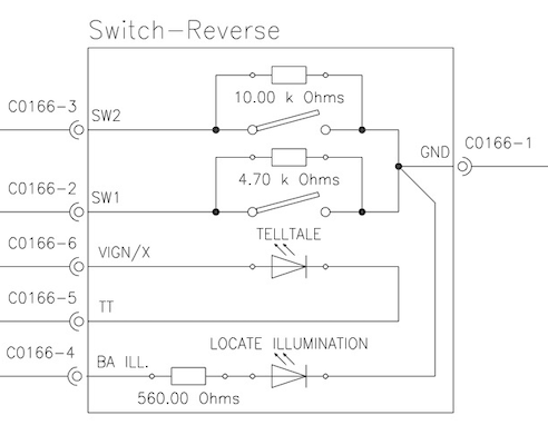
This is the diagram for the Aston Martin drive button. I only use the one switch within the button (SW2).
The latest version of the ciruit diagram and the PCB can be accessed on the Fusion360 site. It's not very pretty (the web viewer have .. issues :). I always try to keep this repo updated with the very latest by using screenshots, but it's also available online. I'm using a free subscription, and can't enable downloads, so it's unfortunately view-only..
My components library can also be found on that site. Not sure how usefull it is though..
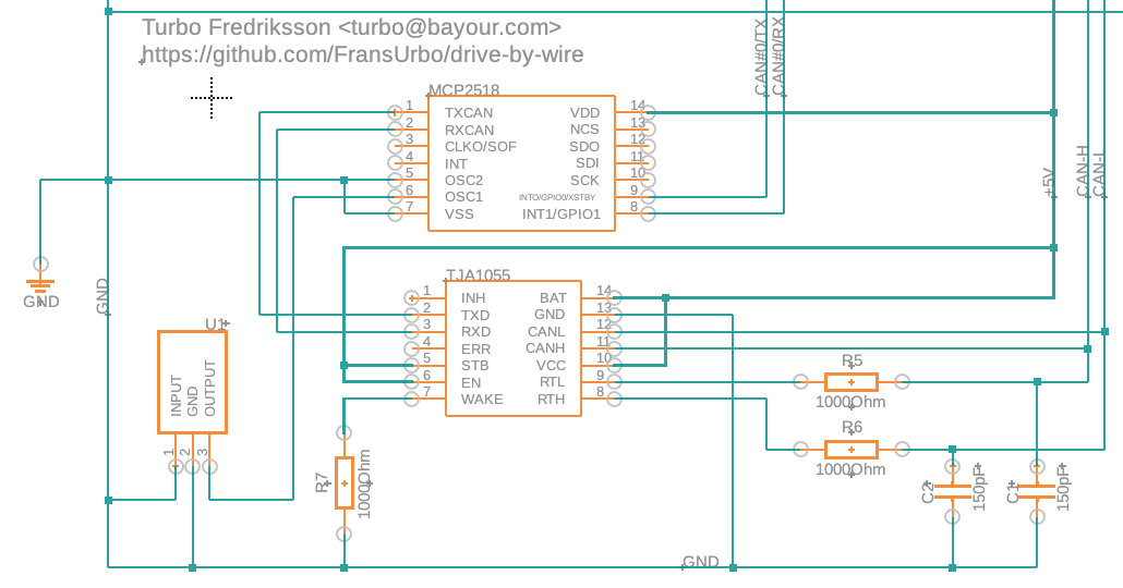
Those CAN bus adaptors I can't apparently used. They're for a high-speed CAN, but the MB I have have a low-frequency, fault-tolerant CAN :(. Something using the TJA1055T1 chip for the CAN and a MCP2515 for interfacing with the Pico. I'll figure something out..
Also, I'm missing the headers for the fingerprint scanner and the actuator in the upper right breadboard.
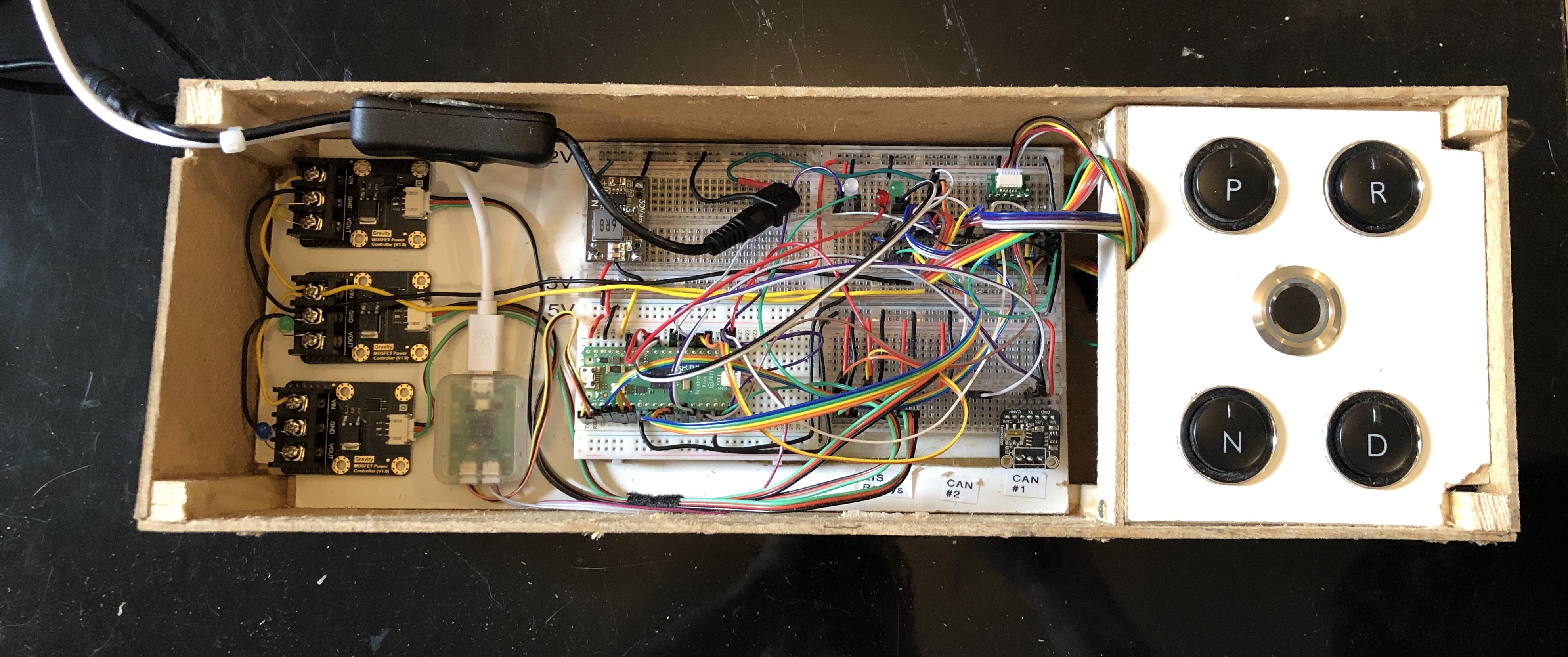
This what it looks like now. I built a box :D :D.
This is the part of CAN-bus from the big circuit diagram. Still working on it, so not sure if it'll work.
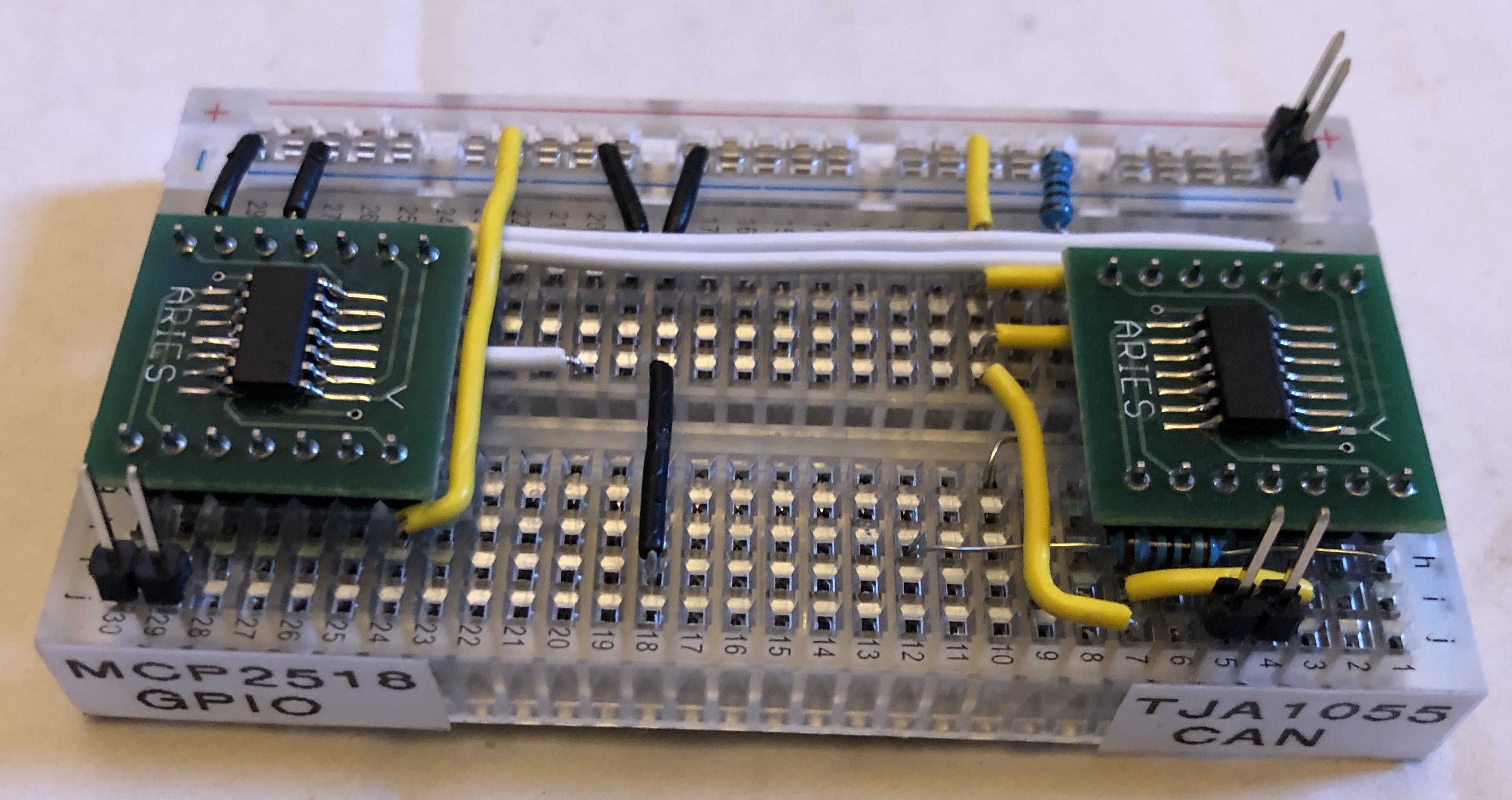
This is the bread board for the CAN-bus. Still missing a few components, but it's getting there.
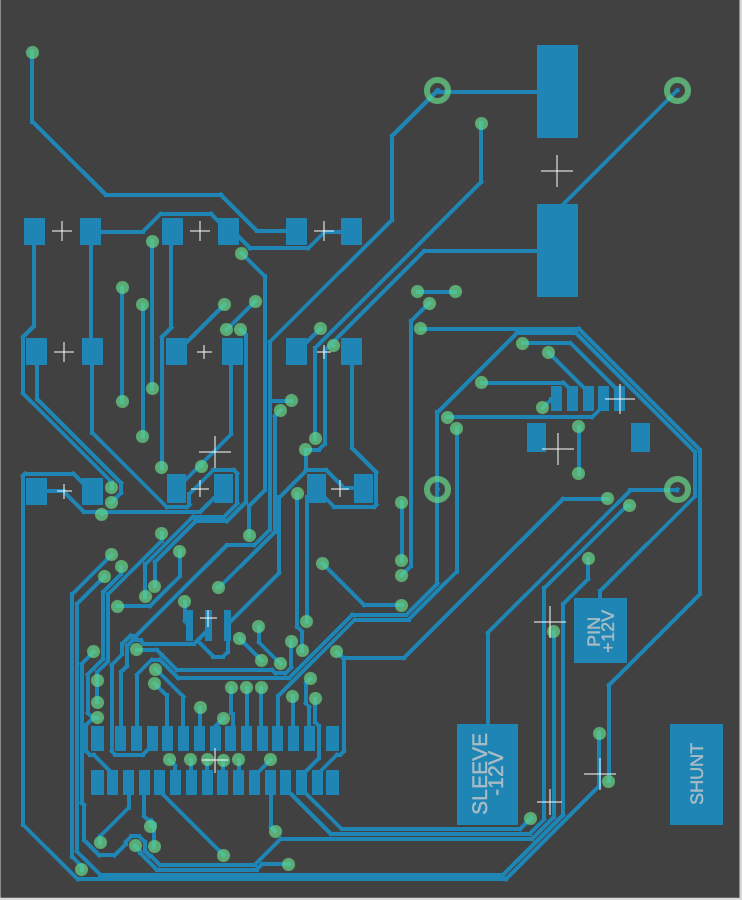
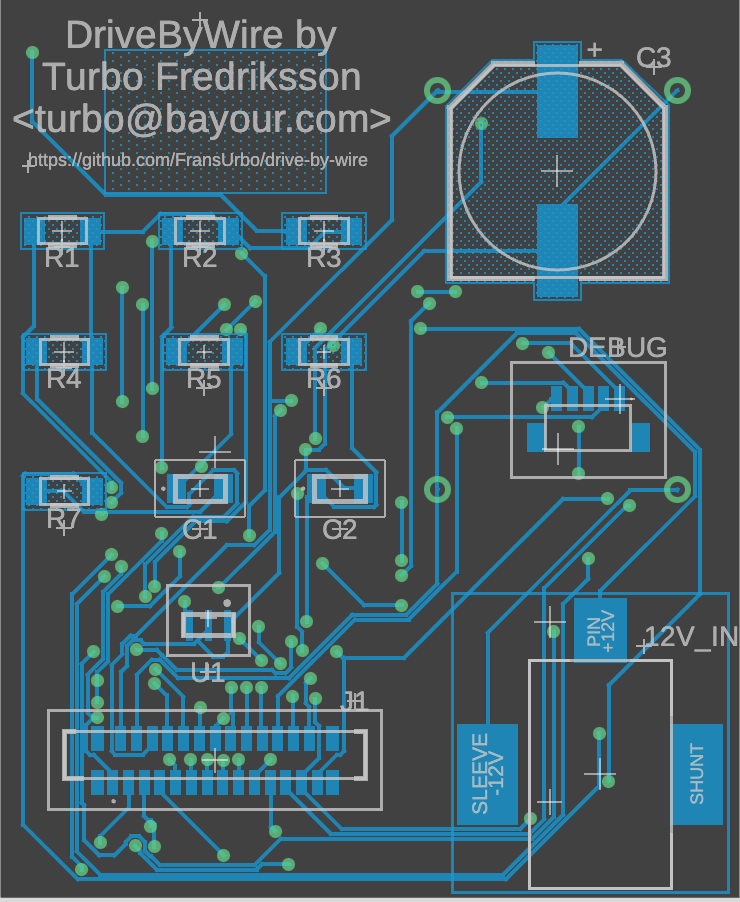
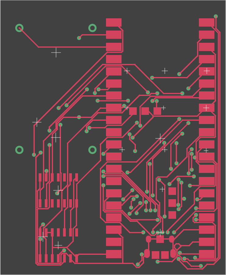
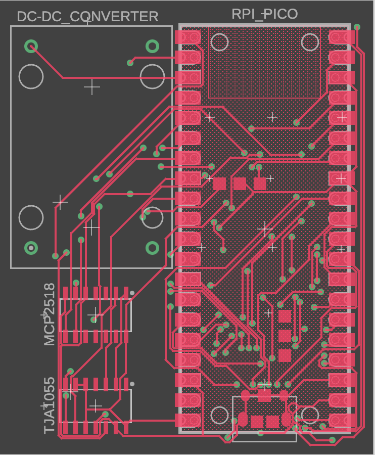
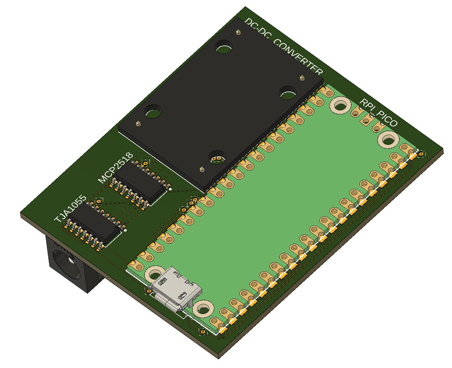
With the help of Fusion360, something I've used a few years now (which is free for students and personal use!), I've managed to create a PCB layout.
It'll probably won't be the last, and I'm not sure if it's valid (not sure about all these signal lines!), but here they are anyway.
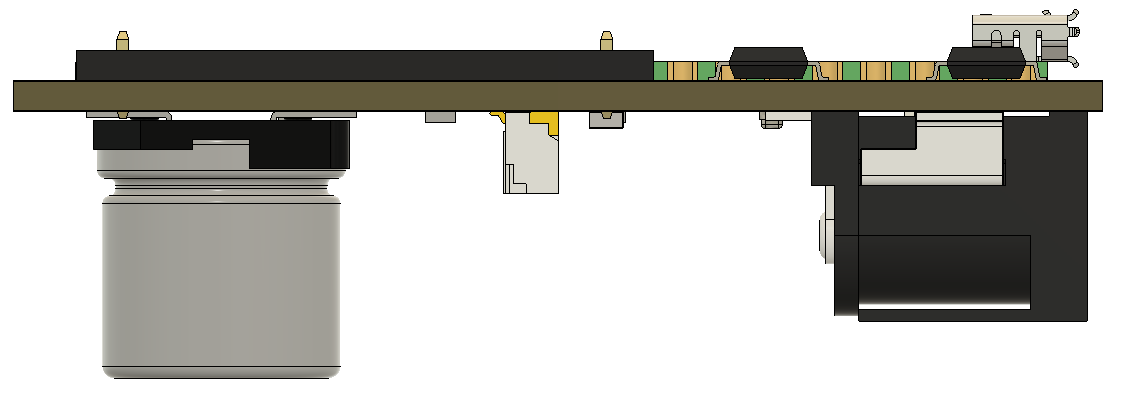
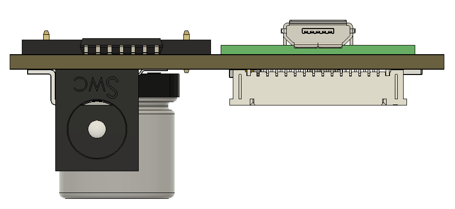
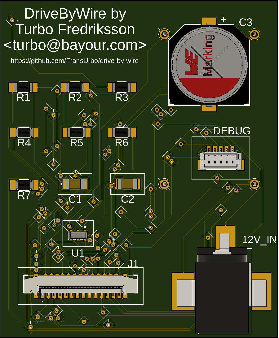
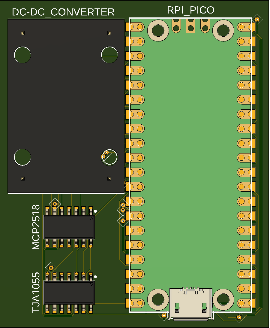
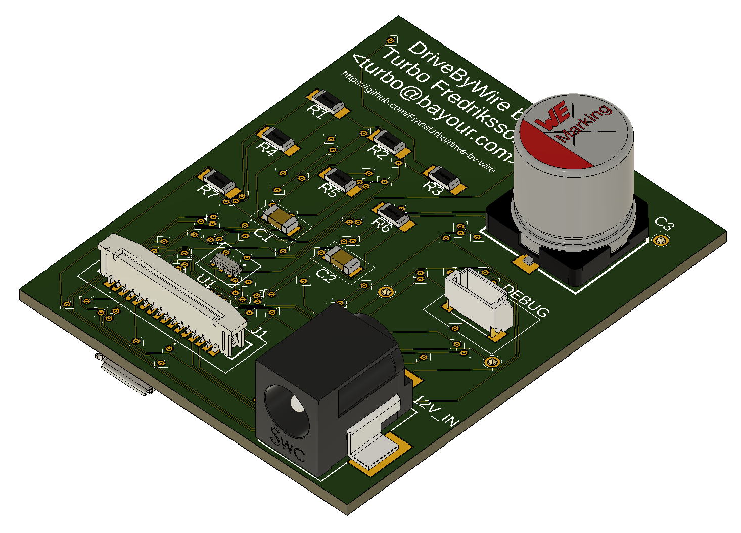
Fusion360 can even generate a 3D object of the PCB! Very pretty! :D
.. and the perspective view.
These are my tests of the individual functionality that I wrote leading up to this project. I have most of it working, the only major thing that's missing is the CAN-bus code and hardware.
- How to control the LEDs, including the NeoPixel (multi-colour LED)
- How to read the buttons and control their LEDs Yes, those are the genuine Aston Martin drive buttons! :).
- How to read, write and verify fingerprint with the fingerprint scanner
- How to control the three MOSFET "relays"
- How to setup and trigger the built-in watchdog on the RPi
The actual DriveByWire source code is getting underway, it's in the code directory. I verify fingerprint, read buttons, turn on LEDs correctly and I move the actuator back and forth.
I do seem to have an issue with the hardware. "Something" is resetting the Pico every now and then. It is likely "something" to do with the actuator, not sure what. The guess is that it's a spike, a feedback from it or that it draws so much power that the power supply I'm using can't take it, drops the power to much (or to fast?) that either the DC-DC converter I have or the Pico can't handle it and resets.
This was a recording of the screen while it was running. It's a day old, and I've done some modifications to the code since them, but this demostrates it fairly well.
And this is what it looked like in action. They where to big for GitHub, so had to put them on my Dropbox account.
The yellow LED in the upper left corner of the box, that's connected to the MOSFET "relay", is "start the car". I THINK it is enough to send +12V to the ECU (Engine Control Unit) on the "start position" pin. We'll see, have to do some experimentation. In this car, I only have to trigger it for the ECU to take over and start the car. So I'm only turning on the MOSFET "relay" for a second. Should be more than enough.
NOTE: There might be an issue with the "blue" (the steering lock on/off) and the "green" (ignition switch on/off) relays. I'm not sure what happens if (when!?) power is lost to the device, OR if it crashes and the watchdog reboots it - for a few seconds those relays will be "off"! What happens if I'm driving and the igntion switch is disabled and the steering lock is enabled!?? The former might not be a problem, although the ECU might .. get confused. But the latter, the steering lock, if that's enabled, as in locks the steering wheel from turning, that will be BAD!!!
I've considered using relays that stays in position and need a trigger to switch, but that might also cause problems - if they're "on" and I've turned the car off and walked away, then they'll do no good!
The steady orange (well, it's not very orange, is it!?? :) and then green LED in the top middle is orange => "starting up" (the module) and when it turns green, it means "all is well". Had the fingerprint not matched, it and the aura around the fingerprint scanner turns red.
As of today, the module will block all button presses while the actuator is moving, to make sure we don't do something .. nefarious :).
In the meantime, this is now simulated by knowing what button is enabled and substracting the button selected. From there, we get a positive or negative value, and we use that to simulate the move of the actuator.
Latest code now stores the button (mode) selected after the actuator have finished moving in the flash memory that's available in the Pico. There's only 2MB flash, but I only need one byte :D. There might be more that I can store there as well in the future.
This flash value is then read on bootup and the correct (latest, before reboot/shutdown/reset) button/mode is then selected automatically.
- Add the bare-bones of CAN-bus read and write. Doesn't actually do anything yet (since I don't have a CAN-bus adapter :), it just logs debug output on what it would do.
- Implement bare-bones actuator test by "moving" (i.e. blink LEDs :) the actuator 1mm backward then forward 1mm.
- Implement checking valet mode. This is now stored in the flash.
- Rewrite the flash code to be "smarter". Actually, easier to use :).
- Update the circuit diagram and PCB with a home-made CAN bus adapter, because I can't use the over-the-shelf ones.
- Remove the EIS/SteeringLock "relay". Can't really cut the power to EIS that way. If there's no power to it, it won't detect the key, and won't allow me to turn the power to the device on! :).
- Update the connectors, get proper CAD drawings and 3D models for them.
- Change the DEBUG connector to a vertical, 5pin, JST connector.
- Change all smaller motherboard connectors with one big one. This should then go to ONE big panel/chassis connector, which can then be split up into multiple leads to the different parts of the car.
- Need to protect the 5V rail from spikes from the actuator control relay, so add a big, fat electrolytic capacitor.
- Because of the new capacitor is HUGE (!!), better rearrange all the connectors to the BOTTOM layer.
- Move the two CAN-bus ICs from the BOTTOM to the TOP layer, to make room for the connectors on the BOTTOM layer.
These changes will allow us to use a different case, where we can put the RPi/Pico, the 5V converter and the CAN-bus controllers on one side, and mount it as low in the case as possible. IF we get an aluminium case, we can even use that as a heat shield for the RPi/Pico CPU, but most importantly, for the 5V converter, which if it draws "a lot" of power, will get hot.
- Rewrite and get the actuator functionality working. Well, mostly anyway. I might have a hardware problem, the Pico just "suddenly" reboots for no apparent reason (no crash etc). MIGHT be a feedback from the actuator, or a dip in voltage/amps when it's moving that the power supply can't quite handle (I DID get a very cheap one!), so the Pico doesn't get enough power..
- Change the motherboard connector. AGAIN!! :D The huge connector I've been looking at never really sat right with me. But found a fairly nice chassis connector, which means I can use a ribbon cable connector for the motherboard. Saves A LOT (!!) of space.
- Add new relay to control feed power (+5V/+12V) to the actuator to be able to control the speed at which it moves.
- Fix a small issue with the CAN-bus adapter.
