Note : There is not graphical interface, working on it...
This program is an electronic circuit simulator that build a graph of the connection between electronic component (such as chipsets, input, output, and some special components) from a configuration file and allow the user to change the state of the circuit input and run the simulation to see the result.
-
input : a component with a single pin directly linked to the command line. Its value is initialized to
undefined. -
clock : a component that works like an input, except its value is inverted after each simulation.
-
true : a component with a single pin that is always true.
-
false : a component with a single pin that is always false.
-
output : a component with a single pin used as the output of a circuit.
- 4001: Four NOR gates.
- 4011: Four NAND gates.
- 4030: Four XOR gates.
- 4071: Four OR gates.
- 4081: Four AND gates.
- 4069: Six INVERTER gates.
- 4008: 4 bits adder.
- 4013: Dual Flip Flop.
- 4017: 10 bits Johnson decade.
- 4040: 12 bits counter.
- 4094: 8 bits shift register.
- 4512: 8 channel data selector.
- 4514: 4 bits decoder.
- 4801: Random access memory.
- 2716: Read only memory
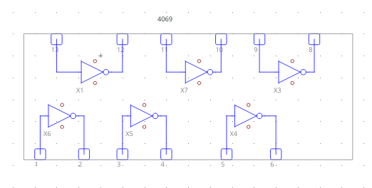
4069 Schematics
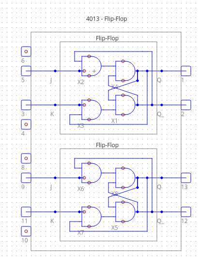
4013 Schematics
Generate the makefile :
make -S .
Compile the program :
make
Execute :
./nanotekspice <".nts" file name>
see USAGE section for more details on .nts file.
This program take a .nts configuration file as first argument, this file is a representation of an electronic circuit.
The program then wait for entry in an infinite loop on the standard input, possible command are :
exit> close the program, sending anEOFalso work.display> display the current state of all pins, also display the tick (current number of execution).simulate> simulate the flow of electricity in the circuit based on the current state of the inputs.loop> make the program loop untilCTRL+Cis received, this is like running thesimulatecommand many times.dump> pretty print the states of every pins just like thedisplaycommand.<input name>=0set input to either0for false,1for true, orUfor undefined.
∼/user@fedora> ./nanotekspice or_gate.nts
> b=0
> a=1
> simulate
> display
tick: 1
input(s):
a: 1
b: 0
output(s):
s: 1
> exit
The .nts configuration files can be found under docs/nts_single or docs/nts_advanced, here is a very basic exemple :
# Basic wire, direct link false to output.
#
# FALSE ---> OUTPUT

.chipsets:
false in
output out

.links:
in:1 out:1
Let's break it down :
-
Comment start with
#and are on a single line, all commented lines are ignored. -
.chipsets:declare the start of the chipsets section which include all basic electronic components such as input and output but also complex chipsets ranging from the 4081 (A chipset with 4 AND gates) to the 4801 (a basic ram stick). -
Everything following
.chipsetsuntil.linksis part of the chipsets section of the configuration file. -
Inside the chipsets section, a chipset is declared as follow :
<chipset name> <given name>. -
.linksdeclare the start of the links section, define the links (or wire) between pins of the various chipsets. -
Inside the links section a link between 2 pin is declared as follow :
<given chipset name>:<pin number> <second chipset name>:<pin number>


